
M0184 Software Guide
voxl-elrs command line tool: bind, flash, and configure the M0184 receiver over CRSF.
Table of contents
Summary
Components
| Component/Repo | Notes |
|---|---|
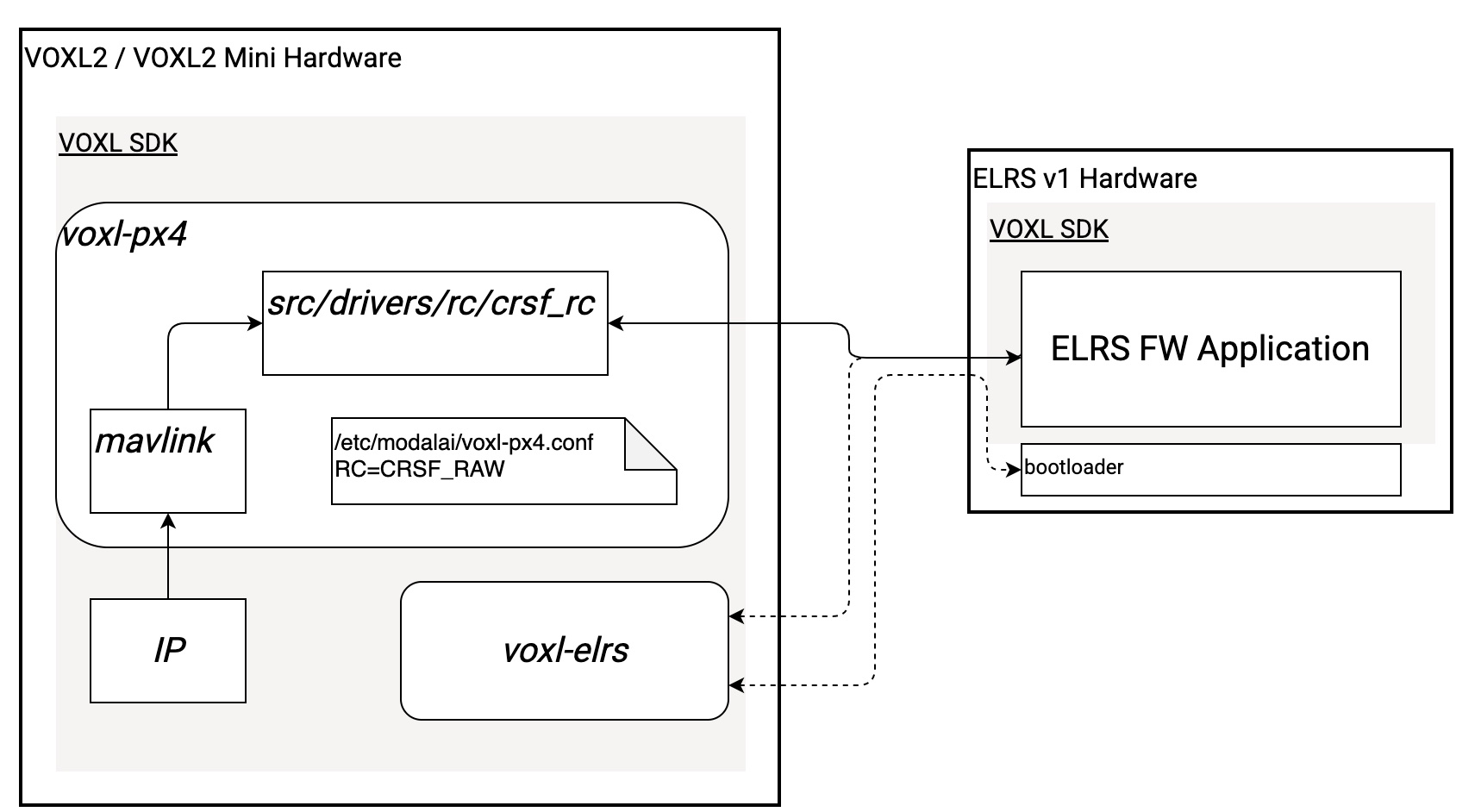
| elrs-build-docker | Docker container that can clone/build FW with ease |
| VOXL SDK | Used to deploy all required software/firmware components to VOXL / ELRS hardware |
| ExpressLRS | Fork of Express LRS supporting ELRSv1 (goal is to mainline) that runs on ELRS v1 (M0184) |
| crsf_rc | PX4 driver running in voxl-px4 that communicates over CRSF to ELRS v1 hardware |
| voxl-elrs | VOXL2 command line utility, used to update FW/config on ELRS v1 from VOXL2, part of the SDK |
| FW bootloader | Open source ExpressLRS bootloader |
Software Block Diagram
Use Cases
The voxl-elrs Utility
voxl-elrs is the on-target command line tool for talking to the receiver over CRSF. It ships with VOXL SDK (1.4.1 or newer) as part of the voxl-elrs package.
With no arguments it picks the transport automatically: the crsf_raw MPA pipe when voxl-px4 is running, otherwise the qup7 serial backend. A serial device path (/dev/ttyUSB0), qup*, or mpa:* value can be passed explicitly with -p, and -b overrides the default 420000 baud.
voxl-elrs ping                # verify the receiver responds
voxl-elrs enumerate           # list every CRSF parameter
voxl-elrs get-param 0         # read a parameter by index
voxl-elrs set-param 1 1       # write a parameter
voxl-elrs get-rc              # current RC channel values
voxl-elrs get-link-stats      # live RSSI / link quality / SNR
voxl-elrs failsafe            # report failsafe state
voxl-elrs bind                # put the receiver in bind mode
voxl-elrs version             # build info
Command names that aren’t built in are matched against the receiver’s own CRSF COMMAND parameters, so commands like bind and unbind execute whatever the connected firmware exposes. save-json / load-json export and import the full receiver configuration as JSON (live, read-only, and command parameters are skipped).
Tab completion for all commands and flags is available by sourcing bash_completions/voxl-elrs from the repo (or dropping it into /etc/bash_completion.d).
Firmware Updates
Firmware binaries ship on the VOXL under /usr/share/modalai/voxl-elrs/firmware (override with the ELRS_FIRMWARE_DIR environment variable); the same catalog lives in the repo under data/firmware.
voxl-elrs list-firmware                  # every binary in the local catalog
voxl-elrs list-firmware modalai_m0184    # filter by target (case-insensitive)
voxl-elrs update                         # auto-detect receiver, flash if newer
voxl-elrs upload-firmware fw.bin         # flash a specific file, even an older one (XMODEM)
voxl-elrs upload-firmware fw.bin esp     # ...or via ESPTool
update auto-detects the connected receiver, compares its installed version against the newest catalog binary, and flashes over XMODEM for MODALAI targets (ESPTool for others).
From a host PC, the -B (Betaflight) and -E (EdgeTX) flags run a serial passthrough first — for example, updating a ModalAI TX module through an EdgeTX radio connected over USB:
voxl-elrs -E -p /dev/ttyACM0 -b 921600 update --target MODALAI_M0193_TX
Presets and SKU Configuration
Receiver settings are managed as JSON presets under /usr/share/modalai/voxl-elrs/config on target (ELRS_CONFIG_ROOT overrides; sources in data/config). Each preset declares which vehicles it applies to (a supported_skus regex list) and a priority; every preset matching the vehicle’s SKU with a priority above 0 is merged in priority order before being applied. Priority 0 presets are only loaded by hand with load-preset.
voxl-elrs list-presets            # every preset in the catalog
voxl-elrs list-presets-for-sku $(cat /data/modalai/sku.txt)   # presets matching this vehicle's SKU
voxl-elrs configure-sku           # apply the merged preset for this SKU
voxl-elrs configure               # firmware update + preset apply in one step
configure is the one-stop provisioning command: it upgrades the receiver firmware from the local catalog if needed (waiting for the receiver to reboot), then applies the merged preset for the SKU in /data/modalai/sku.txt. To apply a different SKU, pass it with --sku; a bare SKU argument is rejected:
voxl-elrs configure --sku MRB-D0014-4-V1-C27-T7
Setting Up PWM Pins
The receiver’s four PWM pins (J4 pads P0-P3) are driven by per-pin mapping curves that translate an RC channel’s value into a PWM output. Pins are normally configured through the SKU presets above — for example stinger_leds.json drives Stinger’s LED bar from RC channel 7 — but the maps can also be inspected and tuned directly:
voxl-elrs pwm-map 0                    # decode pin 0's map and plot it
voxl-elrs pwm-map-set 0 2 0 1500 --mode interp --yes   # move one control point
voxl-elrs pwm-map-tune 1               # interactive tuning shell
pwm-map prints the control points plus an ASCII plot honoring the pin’s map mode (off, step, or interp); pwm-map-set edits a single point with a confirmation preview; pwm-map-tune opens an interactive shell to adjust, plot, and save or discard changes.
Driving PWM Over IP
The PWM pins can also be driven with no RC transmitter at all: a ground station sends button states over IP as MAVLink MANUAL_CONTROL, voxl-mavlink-server forwards them to PX4, and the crsf_rc driver translates configured buttons into RC channel values sent to the receiver — where the PWM maps above turn them into outputs.
Transmitter setup
If using a normal RC transmitter as a USB Joystick such as a RadioMaster Zorro there is a little bit of manual setup required in order for QGC and other applications to recognize the buttons correctly. If using a Logitech USB controller or other where buttons enumerate automatically this section can be skipped.
The following instructions were compiled using a RadioMaster Zorro connected via USB-C to the host PC.
edgeTX v2.10+ is required, in order to validate FW version:
- Press the
SYSbutton, which will bring you to theTOOLSpage - Press the
PAGE <button to navigate to theVERSIONpage - Confirm edgeTX version is >= v2.10
In order to upgrade FW version, follow the instructions here: https://manual.edgetx.org/installing-and-updating-edgetx/update-from-opentx-to-edgetx-1 https://manual.edgetx.org/edgetx-how-to/access-dfu-and-bootloader-mode
In order to translate the RadioMaster Zorro’s channel mappings to buttons. do the following:
- Press the
MDLbutton - Press the
PAGE >button once to navigate to theSETUPpage - Scroll all the way to the bottom until you see the
USB Joysticksection - In the
USB Joysticksection, setModetoAdvanced - Set
If.modetoJoystick - Set
Circ. cuttoNone - Navigate to
[Channel Settings]and press enter Set
CH1-CH4toX,Y,Z,rotX(NOTE: The channels used for switches/buttons need to be on channel 9 or above for them to populate in QGC)- In the
[Channel Settings]menu, navigate to the channel you’d like to setup, i.e.CH9 - Set
ModetoBtn - Set
Positionsto either2POSor3POSdepending on the physical switch - Set
Button no.to be the button numbers in QGC that you’d like this switch to populate (NOTE: A 2POS switch requires two buttons (0,1), whereas a 3POS switch requires 3 buttons (0,1,2)) - Return to the home screen
- Press the
MDLbutton - Press the
PAGE >button 5 times to navigate to theMIXESpage - Scroll down to the corresponding channel which was setup, i.e.
CH9 - Select each channel to be used (hold down button) and set the source as the physical switch you’d like to link to the channel
- In order to finalize changes you may need to disconnect and reconnect the joystick or restart QGC
Example Usage
Let’s say a LED bar was soldered to PWM pin P0, and configured for RC channel 7 (for example Stinger Vision FPV).
A PWM value of 1000 turns it off, a value of 1500 turns it to IR, and a value of 2000 turns it to visible light.
On an RC transmitter, we configure a 3-pos switch to map to buttons 1, 2 and 3.
In voxl-px4, we set PX4 params using params/v1.14/radio_helpers/pwm_via_elrs.params:
- RC_CRSF_BUTTON1 to 1, RC_CRSF_PWMCHN1 to 7, RC_CRSF_PWMVAL1 to 191* (This maps to 1000)
- RC_CRSF_BUTTON2 to 2, RC_CRSF_PWMCHN2 to 7, RC_CRSF_PWMVAL2 to 992* (This maps to 1500)
- RC_CRSF_BUTTON3 to 3, RC_CRSF_PWMCHN3 to 7, RC_CRSF_PWMVAL3 to 1792* (This maps to 2000)
Failsafe
RC failsafe behavior is ultimately the autopilot’s own (e.g. PX4’s RC-loss failsafe parameters) — the VOXL services never synthesize or zero out RC toward the flight controller. What the RC mux in voxl-mavlink-server (en_elrs_rc_mux in /etc/modalai/voxl-mavlink-server.conf, enabled on FPV SKUs via voxl-configure-mavlink-server factory_enable_rc_mux) decides is which source is published on the rc_active MPA pipe for onboard consumers:
- A live ELRS link always wins. While the receiver is delivering RC frames,
rc_activecarries the receiver’s channels, even if RC-over-IP (MANUAL_CONTROLorRC_CHANNELS_OVERRIDE) is also arriving. - ELRS lost while IP RC is connected: the receiver is considered failsafed after 500 ms without an RC frame, and
rc_activeswitches to the IP stream on the next message. - ELRS regained: switches back to the receiver as soon as live frames resume.
- Two IP sources (SDK 1.8.0, voxl-mavlink-server 1.4.20 and newer):
RC_CHANNELS_OVERRIDEis accepted from a ground station over UDP or from onboard services through themavlink_onboardpipe, at the same priority asMANUAL_CONTROL. Up to 18 channels pass through as sent; trailing channels set toUINT16_MAX(or 0 on channels 9-18) are dropped, as PX4 does. Whichever IP source is active keepsrc_activewhile its messages stay fresh, so two senders are never interleaved. When neither is active, the more recent one is selected. - Both lost: IP RC times out after 5 seconds without a
MANUAL_CONTROLmessage, or 1 second without anRC_CHANNELS_OVERRIDEmessage. With the ELRS link also down,rc_activedeliberately goes silent rather than publishing stale values. Consumers see no RC data, and the autopilot’s own RC-loss failsafe governs the vehicle.
Note that MANUAL_CONTROL and RC_CHANNELS_OVERRIDE are always forwarded to the flight controller regardless of the mux; the mux only selects what onboard services see on rc_active.