Power Module v3 Datasheet
Table of contents
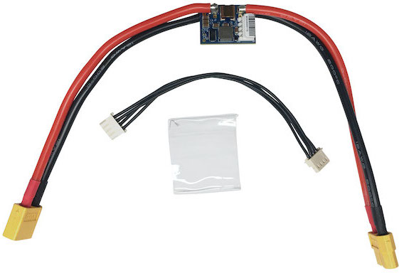
Specification
Part Numbers
Rated up to 6.0ADC output
| Part Number | Description |
|---|---|
| MDK-M0041-1-B-00 | Power Module v3 RevB |
| MDK-M0041-1-B-01 | Power Module v3 RevB, With VOXL/VOXL Flight power cable (Molex 4-pin) (MCBL-00001 |
| MDK-M0041-1-B-02 | Power Module v3 RevB, With Flight Core v1 power cable (JST 6-pin) (MCBL-00003 ) |
| MDK-M0041-1-B-03 | Power Module v3 RevB, With Flight Core v2 power cable (JST 4-pin) (MCBL-00011-1) |
Inputs
For benchtop development, the PS-XT60 wall power supply can be used. NOTE: the VOXL wall power supply with a barrel jack is not supported
XT60 LIPO battery input cable via solder pads (XT60 can be changed to anything with a cable, positive on V+IN pad or BAT_IN 0.025” hole, negative on GND pad or 0.025” hole)
- LIPO range 2S-6S [2 cell (6.4V min, 7.4V nom, 8.4V max) 6 cell ( 19.2V min, 22.2V nom, 25.2V max)]
- Note: Absolute max voltage of design is limited to 28V due to the INA231 current sense IC’s.
- LIPO range 2S-6S [2 cell (6.4V min, 7.4V nom, 8.4V max) 6 cell ( 19.2V min, 22.2V nom, 25.2V max)]
Ouputs
- XT60 LIPO battery cable output via solder pads ((XT60 can be changed to anything with a cable, positive on V+OUT pad or BAT_OUT 0.025” hole, negative on GND pad or 0.025” hole)
- J1: Molex 4-position 22-05-7045 2.5mm R/A male connector, 3A DC continuous per pin @22 AWG (PCB/wire gauge dependent) 4.5A capable regulator for RevA, 6A capable regulator for RevB
- Mates with VOXL and VOXL Flight power input connectors via MCBL-00001 or Flight Core via MCBL-00010
- Pin 1: 5V DC OUT
- Contact ModalAI for alternate voltage outputs, custom DC voltage outputs may impact LIPO input operational range
- Pin 2: DGND
- Pin 3: I2C SCL (5V levels)
- Pin 4: I2C SDA (5V levels)
- Note: Alternate DC voltage outputs above 5V will not impact 5V I2C levels due to dedicated regulator for INA231 devices. Alternate DC voltage outputs below 5V (example 3.3V) will make I2C voltage levels scale lower accordingly (i.e.: ~3.3V).
- Pin 1: 5V DC OUT
- Mates with VOXL and VOXL Flight power input connectors via MCBL-00001 or Flight Core via MCBL-00010
I/O
- I2C bus @ 5V SCL/SDA on output connector for reading LIPO and 5VDC Voltage and Current metrics with Qty-2 INA231
- LIPO on I2C ADDR 0x44, Device U3
- 5V Output on I2C ADDR 0x45, Device U4
Size and Weight
PCB weight is 3.9g
Full APM with XT60 connector is 34g
PCB Dimensions: 21.6mm x 28.75mm
Sensing
A PX4 driver is already integrated starting with PX4 v1.11 and can be viewed here.
The maximum amperage that can be read by the driver before saturating the ADC is 90A, although the XT60 connector limits the system useability to 60A.
One can tweak the Rsense values if needed here
Operating Range/Environmental
- Power Module V3 is qualified for Industrial Temperature operating (ambient) ranges of -40°C to 85°C (non-condensing)
- Not designed for dust or moisture ingress protection or solar load protection (no IPxy rating)
- Heatshrink over design recommended for short protection from other electronic components
- RoHS compliant PCB and PCBA (PCB Assembly)
Also Known As
- May be found referenced as
APM LiteorM0041-1-A(Rev A) /M0041-1-B(Rev B)
2D/3D Drawings
- Dimensions: 21.6mm x 28.75mm
M0041_REVB_CCA_ONLY_NO_WIRES.stp
Note: These 3D files contain all components on them. Some board configurations do not install “DNI” certain connectors or components. Please refer to the included diagrams and design schematics for more detailed information, or contact ModalAI, or post a question on our support Forum.
PX4 Driver
scr/drivers/powermonitor/voxlpm