VOXL 4-in-1 ESC Datasheet
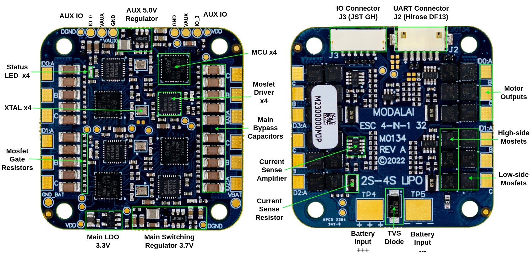
Hardware Overview
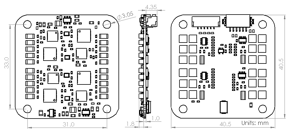
Dimensions
Specifications
| Details | |
|---|---|
| Power Input | 2-4 S Li-Po (5.5-18V) |
| XT30 connector (suggested) | |
| Power Output | Single AUX power output at 5.0V (adjustable via resistor) 500mA (can be used for Neopixel LEDs) |
| Performance | 4 channels at 10A+ maximum continuous current per channel (depends on cooling) |
| Maximum RPM : 50,000+RPM for a 12-pole motor | |
| Features | Open-loop control (set desired % power) |
| Closed-loop RPM control (set desired RPM), used in PX4 driver | |
| Control LED colors of external LED Strip (Neopixel) | |
| Generate tones using motors | |
| Real-time RPM feedback | |
| Communications | Supported by VOXL Flight, VOXL and Flight Core |
| Dual Bi-directional UART (3.3VDC logic-level) | |
| PWM input supporting 1-2ms and OneShot125 (more protocols coming soon) | |
| Connectors | UART: Hirose DF13 6-pin |
| PWM Input: JST GH 6-pin | |
| AUX Regulated Output Connectors: N/A (solder pads) | |
| Motor Output Connectors: N/A (solder pads) | |
| Hardware | MCU : STM32F051K86 @ 48Mhz, 64KB Flash |
| Mosfet Driver : MP6530 | |
| Mosfets : AON7528 (N-channel) | |
| Individual Current Sensing : 4x 2mOhm + INA186 | |
| ESD Protection : Yes (on UART and PWM I/O) | |
| Temperature Sensing : Yes | |
| On-board Status LEDs : Yes | |
| Weight (no wires) : 9.5g | |
| Motor Connectors: N/A (solder pads) | |
| PX4 Integration | Supported in PX4 1.12+ |
| Code | |
| Resources | Manual |
| PX4 Integration User Guide |
Connector Information and Pin-outs
UART Connector J2
- Used for UART communication with the ESC
- Connector on board : Hirose DF13A-6P-1.25H
- Mating connector : DF13-6S-1.25C
- Pre-crimped wires : (Digikey) H4BBT-10112-B8 or similar
- Connector is compatible with VOXL ESC V1, except V2 board has additional UART2 functionality
- 3.3V signals (5.0V input is acceptable)
| Pin > | 1 | 2 | 3 | 4 | 5 | 6 |
|---|---|---|---|---|---|---|
| Function > | VREF_OUT | UART RX (IN) | UART TX (OUT) | RESERVED | GND | RESERVED |
PWM Input / Output Connector J3
- Used for PWM input or output
- Connector on board : BM06B-GHS-TBT
- Mating connector : GHR-06V-S
- Pre-crimped wires : (Digikey) AGHGH28K152 or similar
- 3.3V signals (5.0V input is acceptable)
| Pin > | 1 | 2 | 3 | 4 | 5 | 6 |
|---|---|---|---|---|---|---|
| Function > | VREF_OUT | PWM0 | PWM1 | PWM2 | PWM3 | GND |
Neopixel LED Support
![]()
- Two independent Neopixel RGB LED outputs are available, up to 32 LEDs each
- Use test points labeled
IO_0andIO_3in the AUX IO section of the ESC - IO_0 and IO_3 are connected to ESC
ID0 PB8andID3 PB8respectively (3.3V levels) - VAUX output provides 5.0V output for the LED array
- Test tools: voxl-esc-neopixel-test.py
- Integration with PX4 is done via
voxl_escdriver andmodal_io_bridge
PWM Inputs / Outputs
- Four independent PWM input / output pins are available, one pin per ESC channel
- Use J3 connector (pins 2,3,4,5 corresponding to PWM 0,1,2,3)
- PWM pin 0 is connected to ESC ID0, PWM1 -> ESC ID1, and so on (3.3V levels)
- PWM input enabled in ESC firmware
39.13or later, PWM output in39.18or later - Operating mode of PWM pins
- Default mode of PWM pins is PWM input. In absence of UART communication, PWM pins can be used to control the ESC power using standard PWM signal (1-2ms)
- Upon detecting any UART communication by ESC, PWM input is disabled until power reset
- PWM output can be enabled by sending specific message to the ESC via UART interface
- PWM output mode specifications
- 3 frequency modes (50hz, 200hz, 400hz)
- enable or disable timeout (0.5s). If timeout is enabled, PWM output will be disabled (set to low state) after 0.5s of no commands
- output range 0-2200 us with 0.05us resolution, special value of 2201us will force HIGH state (can be used as GPIO)
- Test tools: voxl-esc-pwm.py
- Integration with PX4 is done via
voxl_escpx4 driver andmodal_io_bridge. test app