The ModalLink system uses Band 3 modems to operate in the DOD’s 1800MHz spectrum. The same add-on board can be used for international use.
Specicifcation
Value
CAT4 LTE Band
1,2,3,5,7,8,20,28,38,40
Bandwidth
up to 150/50 Mbps Download/Upload
SIM Cards and Supported Networks
The modem card requires the use of a Nano SIM card.
AT&T, Verizon and T-Mobile are supported. For Band 3 support, the VOXL-ACC-LTEH-DOD modem is requiered and Band 3 SIM cards need to be requested through ModalAI.
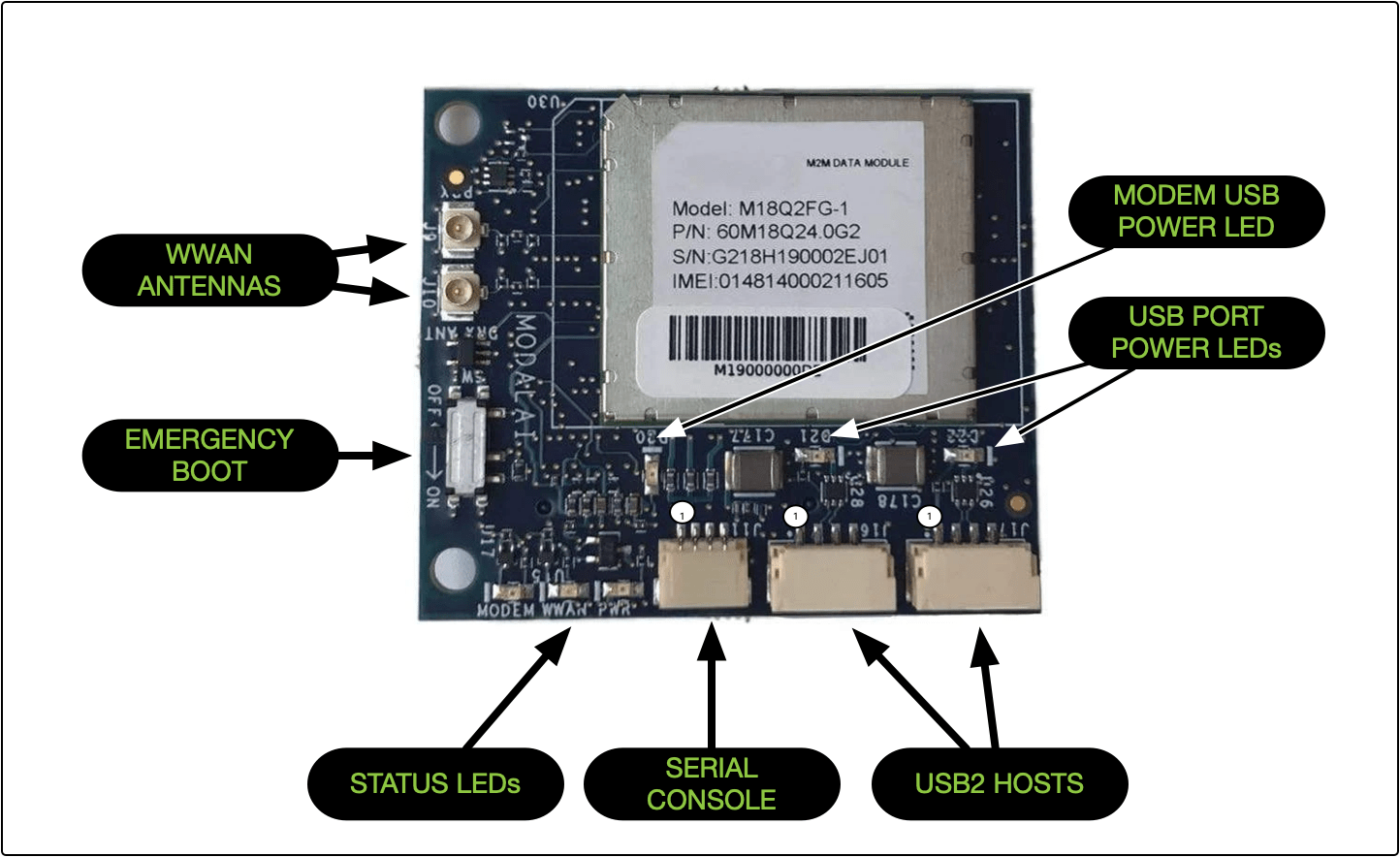
LEDs
Status LEDs
LED
Description
PWR
Illuminates GREEN when the board is powered
MODEM
Illuminates GREEN when the modem is powered
WWAN
Illuminates solid BLUE when connected to the network
USB LEDs
The Modem USB Power and USB Port Power LEDs illuminate green to indicate the USB bus and ports are powered
Connector Pinouts
J11 - Serial Debug Port
Connector - BM04B-SRSS-TB
Mating Connector - SHR-04V-S-B
Pin
Description
1
3.3 VDC
2
UART_RX_3P3V
3
UART_TX_3P3V
4
GND
J16 - USB Port 1
Connector - 4 Position JST GH, Vertical, BM04B-GHS-TBT
Mating Connector - JST GHR-04V-S
Pin
Description
1
5VDC (500mA max)
2
D-
3
D+
3
GND
J17 - USB Port 2
Connector - 4 Position JST GH, Vertical, BM04B-GHS-TBT
Mating Connector - JST GHR-04V-S
Pin
Description
1
5VDC (500mA max)
2
D-
3
D+
3
GND
RF Characteristics
Specicifcation
Value (3GPP)
TX Power (LTE)
23 dBm (typical)
TX Power (WCDMA)
24 dBm (typical)
RX Sensitivity (LTE)
-102 dBm (typical)
RX Sensitivity (WCDMA)
-110 dBm (typical)
Environmental
Operating Temperature
Parameter
Min
Max
Unit
LTE System Functional
-40
+60
ºC
Module Functional
-40
+85
ºC
Module 3GPP Compliant
-20
+60
ºC
Emergency Boot Switch
Typically left in the OFF state, this switch can be used to enable emergency boot mode.