VOXL m500 Gimbal User’s Guide
Table of contents
Note: Due to difficulties sourcing low cost and available gimbals, ModalAI no longer has any officially supported gimbal solutions at this time
Gimbal Version Summary
As a convenience, versions of the VOXL-m500 are available to test out a gimbals. Links to the off the shelf gimbal source are provided along with any configuration software used. The factory setup used is provided here as well to help others adding gimbals of their own choosing.
Notes On Gimbal Control Limitations
No PX4IO/AUX Outputs
The m500 houses the VOXL-Flight board, which only supports 8 PWM outputs, and not the additional AUX port. For this reason, the gimbal control is limited to using the RC AUX passthrough feature of PX4, providing pitch/yaw control of the gimbal only using RC AUX passthrough.
Camera Trigger Bug
Using QGroundControl, you can enable camera triggers on PWM outputs, like channels 5 and 6. At least in PX4 FW v1.10, there’s an issue that causes these channels to get overwritten and zeroed out in some cases, causing problems with camera trigger. A non-warrantied work around is as follows. You’d need to update the ROMFS/px4fmu_common/mixers/quad_x.main.mix mixer and rebuild the firmware such that the file contains only this content:
R: 4x 10000 10000 10000 0
MAVSDK Behavior with MAVLink
MAVSDK works by sending MAVLink commands to the flight computer in order to control the drone. When the drone is being operated by MAVSDK, it is placed in “offboard” mode. During operation in “offboard” mode, the drone is still able to respond to “RC_CHANNELS_OVERRIDE” commands if configured correctly. This allows the user to manually control gimbals using RC pass-though from the RC input to PWM outputs.
Though “RC_CHANNELS_OVERRIDE” commands work at the same time as MAVSDK is operating, they do not work if an RC transmitter is connected. The flight computer will only respond to the first type of input it sees. If the flight controller receives “RC_CHANNELS_OVERRIDE” MAVLink messages first, then all RC transmitter input is ignored until the flight computer is rebooted. If the flight controller sees RC transmitter data before any “RC_CHANNELS_OVERRIDE” MAVLink messages are received then all “RC_CHANNELS_OVERRIDE” messages are ignored.
MAVSDK can operate regardless of which form of input is used (“RC_CHANNELS_OVERRIDE” messages or RC transmitter input) but when in offboard mode, MAVSDK will cause the flight computer to ignore flight control input for thrust, yaw, roll and pitch. All other RC channel inputs will be honored if appropriate (such as an RC channel configured to be an RC pass-through.)
MRB-MD001-2-01-G1
Overview
Camera not included
For this gimbal, the recommended camera is something like the Mobius Pro Mini Action Camera based on form factor alone. We are not qualifying this camera’s performance, but based on size, weight and geometry, this camera has been shown to work well in our testing wih the gimbal referenced below.
The -G1 configuration consists of:
It is configured with the following:
- Configuration Software: Version 2.2b from https://www.basecamelectronics.com/downloads/8bit/ - WARNING: DON’T UPGRADE THE CONTROLLER FIRMWARE. THIS APPEARS TO BRICK THE GIMBAL CONTROLLER
- Useful links for tuning: here and here
Configuration
Wiring Guide
TODO: Diagram
Gimbal control handled through the PWM output connector on VOXL-Flight J1007, Flight Core J7
| Pin # | Signal Name | Connection |
|---|---|---|
| 1 | 5VDC | NC |
| 2 | PWM_CH1 | Motor 1 |
| 3 | PWM_CH2 | Motor 2 |
| 4 | PWM_CH3 | Motor 3 |
| 5 | PWM_CH4 | Motor 4 |
| 6 | PWM_CH5 | Gimbal Pitch/Tilt Control (3.3V) |
| 7 | PWM_CH6 | Gimbal Yaw Control (3.3V) |
| 8 | PWM_CH7 | Not used |
| 9 | PWM_CH8 | Not used |
| 10 | GND | NC |
PX4 Param File
For reference, a PX4 parameter for setting up a Spektrum DX8 with this gimbal using channels 8/7 to pitch/yaw and enabling outputs on bootup can be found here
AUX Passthrough RC Channel
The AUX1/2 passthrough RC channels are configured via RC_MAP_AUX1 and RC_MAP_AUX2. These two channels can be configured to control pitch/yaw control on the gimbal from the RC transmitter. In the param file referenced above these are set to 8 and 7.
Auxillary Outputs
The Quadrotor x airframe is supported by the m500, which provides us feed-through of RC AUX1 and AUX2 channels to PWM_CH5 and PWM_CH6 (pins 6 and 7 above) respectively.
The AUX ouptut signals may be disarmed on bootup and only enabled after arming the vehicle which may not be desirable debugging. Setting the COM_PREARM_MODE mode to 2 (Always) enables the outputs on bootup (this is shown in the param file referenced above).
PWM Signals
The PWM signals PWM_CH5 and PWM_CH6 (pins 6 and 7 above) have a range of 1000 to 2000 us and are controlled by the PWM_AUX_MIN5/PWM_AUX_MIN6 and PWM_AUX_MAX5/PWM_AUX_MAX6 parameters. These are left as the PX4 default.
Also by default, the output is 1500 us when disarmed, which is configured by PWM_AUX_DISARMED.
Usage
Power Up
The gimbal receives power via the battery (not through the DC plug available on the power module). Upon attaching the battery, the gimbal will self stabilize in roughly 6 seconds. You can hold the camera in position during this time to stabilize into a starting point of your desire.
Pitch / Yaw Control
Using the DX4 transmitter with the params setup as above:
| Channel # | Switch Type | Control | Notes |
|---|---|---|---|
| 8 | Dial | Pitch | rotate to middle to have 0 degrees, rotate left/right to pitch up/down |
| 7 | 3-Position | Yaw | middle position no movement, up yaw left, down yaw right |
Streaming to QGroundControl
Hardware Setup
Streaming a video feed from a Mobius Pro Mini Action Camera to QGroundControl requires the use of a Flight Core or VOXL Flight.
The following additional hardware is required to stream video from the camera through VOXL to QGroundControl.
| Part Number | Description | Link |
|---|---|---|
| MCBL-00009-1 | USB Cable (Host, 4-pin JST to USB 2.0 Type A Female) | Purchase |
| Camera USB Cable | USB Cable included with camera (Mini USB) |
One of the following VOXL Add-on boards is required.
| Part Number | Description | Link |
|---|---|---|
| MDK-M0048-1 | VOXL Microhard Modem Add-on | Purchase |
| MDK-M0078-1 | VOXL USB Expansion Board with Fastboot and Emergency Boot | Purchase |
| MDK-M0030-1 | VOXL Cellular LTE and USB hub add-on | Purchase |
Before beginning setup, make sure the VOXL is disconnected from both it’s power source and it’s USB to host PC cable
Attach the add-on board to the VOXL and make sure that the boot switch(es) are turned off or to the left
Plug the jst side of the MCBL-00009-1 USB Cable into the add-on board
Plug the camera’s USB cable into both the camera and the USB female side of the MCBL-00009-1 USB cable
Power the VOXL
Switch the Mobius camera into webcam mode by pressing the
Shutterbutton. (Button with picture of camera)
Software Setup
Before starting the camera stream, make sure your vehicle is connected to QGroundControl. Instructions on how to do so over WiFi can be found here: How to Connect QGroundControl to VOXL using WiFi
If ffmpeg is not currently installed on your VOXL it can be built and installed by following the instructions here: voxl-ffmpeg
- On VOXL, start the video stream by using the following command:
ffmpeg -i /dev/video2 -f mpegts udp://GCS_IP:4242
Replace GCS_IP with the IP Address of your Ground Control Station that is connected to the VOXL.
FFmpeg has a large variety of flags that can be set in order to change the encoder settings and modify the resolution, framerate, bitrate, etc. of the video stream. The documentation can be found on the FFmpeg Website.
In QGC, press the purple QGC logo in the top left corner in order to access the
Application Settingsmenu.Under the
Generaltab, scroll down until you find theVideosection.Under the
Video Sourcedropdown, chooseMPEG-TS (h.264) Video Stream.In the
UDP Portfield enter the default:4242You will now be able to view the video stream under QGC’s
Flyview.
PID Tuning
To compliment the user guide above, here’s a high level walkthrough:
- Open the SimpleBGC GUI
- Connect to the gimbal using a micro usb
- On the GUI, under Connection, click the dropdown and select the COM port. Should connect automatically
- On the top there are several tabs to select from: Basic Tab, Advanced Tab, RC Settings Tab, Follow mode Tab, Menu Button Tab, Realtime Data Tab, Firmware upgrade Tab
NOTE: Avoid flashing the newest firmware. Will brick the device. Would suggest avoiding the Firmware Upgrade tab altogether.
- Before altering any values, would recommend saving the values to reference back if needed.
- The Basic Tab, allows to set the PID’s, Motor configuration, Sensor configuration and External FC Gain
- Highly recommend calibrating the ACC. and GYRO
- The PID’s work well in default settings, but for more custom settings, change the values to your liking. Too high values and the gimbal becomes very twitchy and too low values make the gimbal sluggish, in general:
- P - is like the power/resistance to change
- I - the speed to which the gimbal will return to center
- D - stabilizes the bumps
- Power is the amount of power each motor is receiving. Can be set anywhere from 0-250. Recommend starting out anywhere from 80-120 to start. Too high a value and the motors start getting hot, too low and there’s not enough power to combat the wind and motions of the camera.
- Invert should be defaulted after plugging in the gimbal, if not select Auto
- NUM Poles should be 14, unless different motors are used then this should be changed to match the poles of the motor
- External FC Gain is left alone
- Sensor Axis should’ve been recorded correctly after connection to usb. If not, use -Z, -Y for Axis Top and Right respectively
- Advanced Tab, leave AHRS alone, good as is.
- In Timings, Serial port speed is left alone
- PWM Frequency is altered to High(silent)
- RC Settings Tab, under RC Input mapping, Source: PWM
- ROLL: RC_ROLL
- PITCH: RC_PITCH
- YAW: EXT_PITCH
- CMD: no_input
- Command Assignment is left alone
- Adjust settings here for angle of gimbal and speed:
| MIN.ANGLE | MAX.ANGLE | ANGLE MODE | LPF | SPEED MODE | SPEED | FOLLOW.% | |
|---|---|---|---|---|---|---|---|
| ROLL | -45 | 45 | X | 3 | 50 | 0 | |
| PITCH | -60 | 60 | X | 3 | 50 | 0 | |
| YAW | -100 | 100 | 3 | X | 50 | 0 |
- Use Realtime Data Tab, simultaneously as tuning the PID’s. The goal is to get a smooth slope with the least bit of oscillations with the fastest return to center
Arducam UVC Camera
The Arducam is the recommended UVC camera for the m500. There are many different Arducams to choose from depending on your requirements. You can find the Arducam Specs and Selection guide by going here.
The Arducam B0229 is an excellent choice:
- Field of View (FOV): D=105°, H= 90°, V= 65°
- Supports MJPG 15fps@ 3264x2448, 30fps@1080P, and YUY2 30fps@ 640x480 formats.
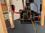
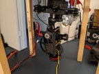
Arducam Gimbal Mounting
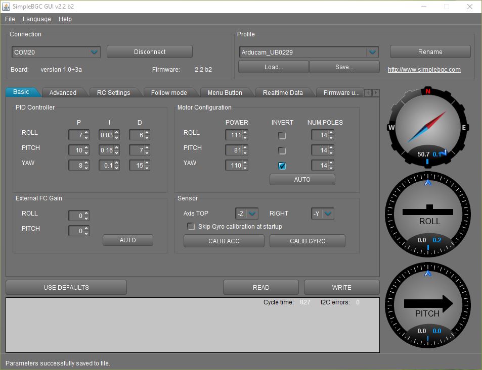
- Gimbal SimpleBGC PID profile settings can be found here (right-click then Save link as…).
- SimpleBGC PID settings screenshot:
We created a mount that you can print on a 3D printer. Download the STEP file here.
Front and Bottom views of Arducam Gimbal Mount: