Microhard Add-on Datasheet
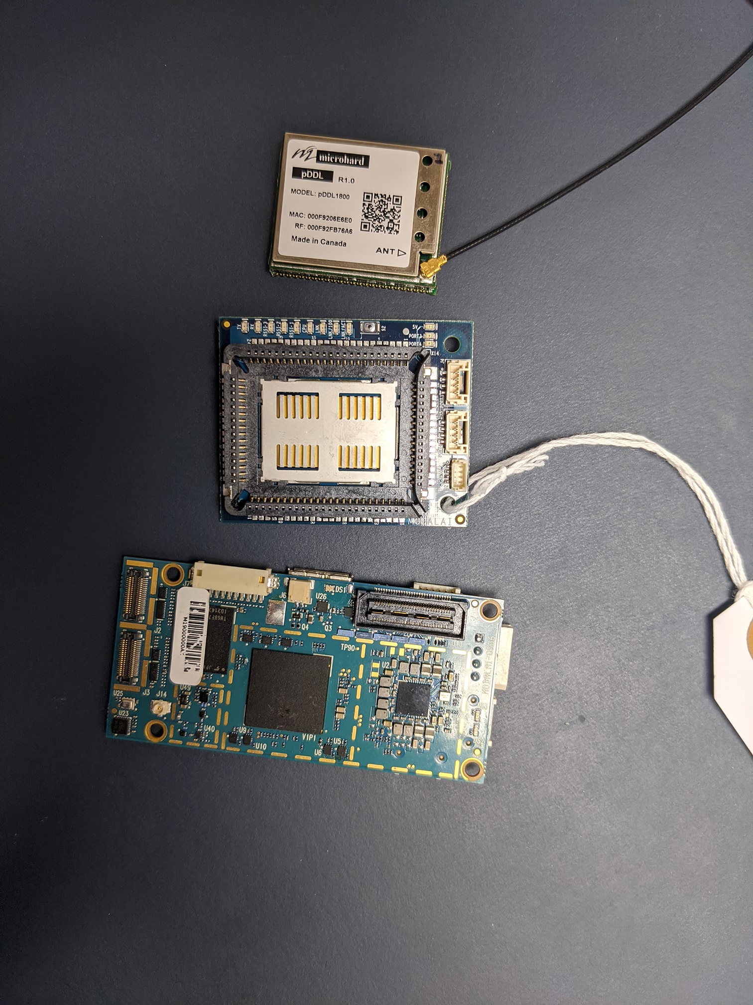
This expansion board plugs directly into VOXL and supports pDDL modules from Microhard (not included).
Once a module is installed and connected to VOXL, this unit can be paired with the ModalAI Microhard USB Dongle.
Table of contents
- Specification
- Board Connections and I/O
- Configuration
- Connector Pinouts
- Mechanical Drawings
- Additional Pictures
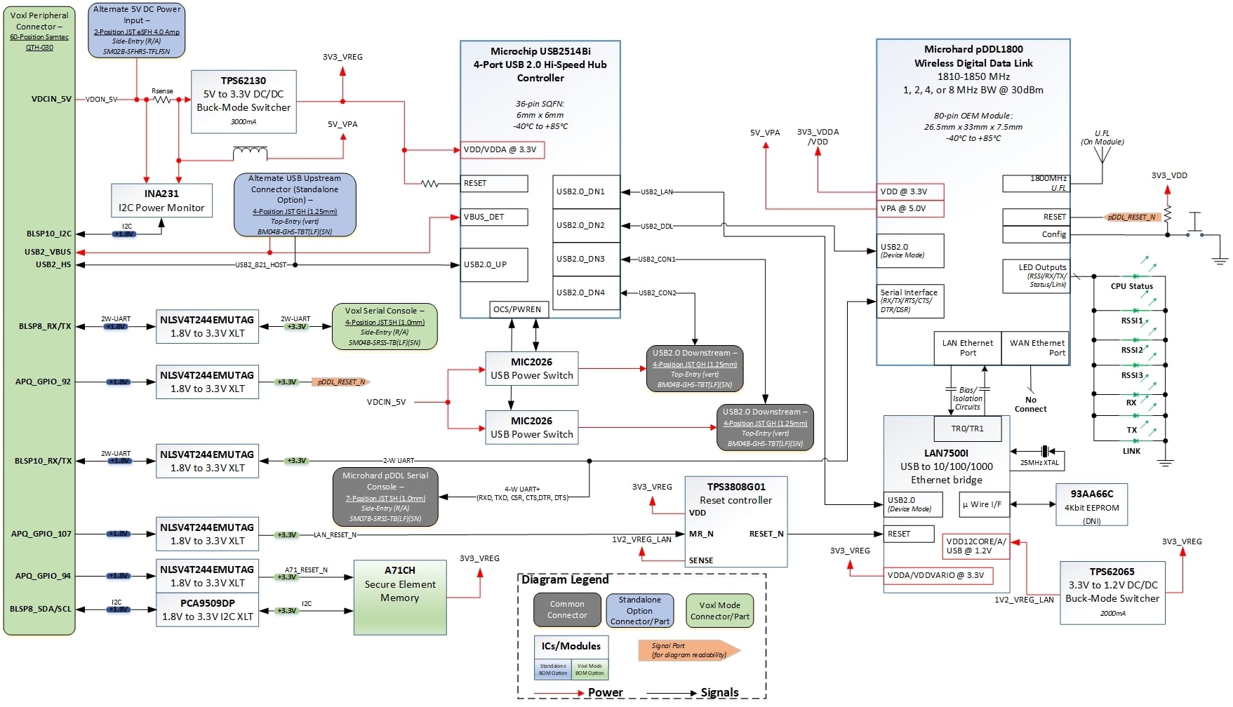
Specification
Block Diagram
Part Numbers
| Part Number | Silkscreen Marking | Description |
|---|---|---|
| MDK-M0048-1-01 | M0048 REV A | Moved to LAN7500 ethernet controller for better compatibility with Android |
| VOXL-ACC-MH-1 | M0012 REV A | Initial Release |
Physical Specification
| Specicifcation | Value |
|---|---|
| Weight | 12g |
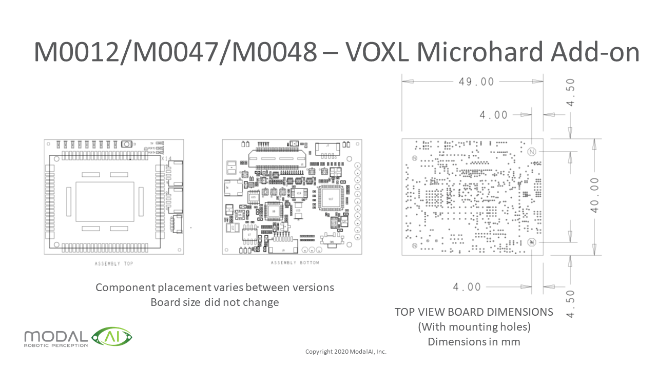
| Dimensions | 49 x 40mm |
| Antenna Connector | ?? UFL-R-SMT-110 |
| Recommend Antennas | |
| Debug Console Connector | ?? SM04B-SRSS-TBLFSN |
| Debug Console Matimg Connector | ?? SHR-04V-S-B |
| USB2 Client Connectors | 4 Position JST GH, Vertical, BM04B-GHS-TBT |
| USB2 Client Mating Connector | JST GHR-04V-S |
| J1 Connector (bottom of board) | Samtec Inc, MPN: QTH-030-01-F-D-K |
| J1 Mating Connector | Samtec Inc., MPN: QSH-030-01-L-D-A-K |
Power Consumption
| M0048 Configuration | 5V Power Consumption (mA) |
|---|---|
| Baseline (USB Hub, Glue Logic, All LEDs ON) | 315 |
| Baseline plus Qty-2 USB Peripherals at Max 500mA* | 1375 |
| Baseline + Qty-2 DS USB* + Microhard 900MHz @ 10dBm | 2800 |
| Baseline + Qty-2 DS USB* + Microhard 900MHz @ 30dBm | 3700 |
| Baseline + Qty-2 DS USB* + Microhard 2400MHz @ 10dBm | 2500 |
| Baseline + Qty-2 DS USB* + Microhard 2400MHz @ 30dBm | 3100 |
*For each of the two downstream peripherals removed from the hub, subtract 500mA plus ~30mA logic from the power requirement.
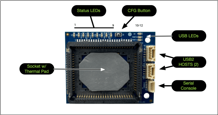
Board Connections and I/O
Top of Board
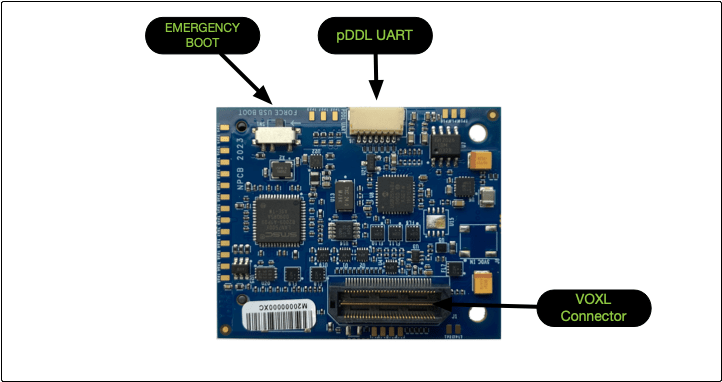
Bottom of Board
USB Connections
You can connect up to two USB-clients to the USB2 Host ports on the top of the board. A MCBL-00009 cable can be used, this is a 4-pin JST to USB Female Type A cable.
You can connect the carrier board to a host computer using the USB port on the bottom of the baord. Connect to a host comptuter with MCBL-00010, which is a 4-pin JST to microUSB female cable.
LEDs
| Index | LED | Description |
|---|---|---|
| 1 | TX | Flashes GREEN indicating wireless TX traffic |
| 2 | RX | Flashes GREEN indicating wireless RX traffic |
| 3 | RSSI-3 | Flashes GREEN to indicate the Received Signal Strength on the wireless link |
| 4 | RSSI-2 | Flashes GREEN to indicate the Received Signal Strength on the wireless link |
| 5 | RSSI-1 | Flashes GREEN to indicate the Received Signal Strength on the wireless link |
| 6 | CPU | Solid GREENindicates power to module and normal operation, flashing indicates boot or FW upgrade status |
| 7 | LAN | Can be programmed to flash GREEN to indicate MH Link to the Ethernet Controller on board |
| 8 | LAN/100 | Used in conjunction with 9. Can be programmed to flash GREEN to indicate Link and Speed or Link and Speed and Activity |
| 9 | LAN/ACT | Used in conjunction with 8. Can be programmed to flash GREEN to indicate Link and Speed or Link and Speed and Activity |
| 10 | 5V | Illuminates solid GREEN indicating 5VDC USB bus power enabled |
| 11 | Port3 | Illuminates solid GREEN indicating Port 3 USB power enabled |
| 12 | Port4 | Illuminates solid GREEN indicating Port 4 USB power enabled |
Index 8 and 9 (LED LAN/100 and LED LAN/ACT ) config options.
Index 8 (LAN/100) config flags
| SPD_LED_FUNCTION | Speed (Mbps) | Index 8 (LAN/100) |
| 0 | No Link | OFF |
| 0 | 10 | OFF |
| 0 | 100 | Flashes |
| 0 | 1000 | Flashes |
| 1 | No Link | OFF |
| 1 | 10 | OFF |
| 1 | 100 | BLINK |
| 1 | 100 | BLINK |
Index 9 (LAN/ACT) config flags
| LED_2_FUNCTION | Index 9 (LAN/ACT) |
| 0 | Link and Activity LED |
| 1 | Activity LED |
CFG Switch
Can be used to reset all settings to default values required for a Slave module.
Configuration
Slave Configuration
To reset all settings to the default values required for a Slave module, press and hold the CFG Button, once the CPU LED begins to flash, continue to hold for 5 seconds, then release.
The module will then reset all settings to the default values required for a Slave module
Connector Pinouts
J4 - USB Port 3
- Connector - 4 Position JST GH, Vertical, BM04B-GHS-TBT
- Mating Connector - JST GHR-04V-S
| Pin | Description |
|---|---|
| 1 | 5VDC (500mA max) |
| 2 | D- |
| 3 | D+ |
| 4 | GND |
J5 - USB Port 4
- Connector - 4 Position JST GH, Vertical, BM04B-GHS-TBT
- Mating Connector - JST GHR-04V-S
| Pin | Description |
|---|---|
| 1 | 5VDC (500mA max) |
| 2 | D- |
| 3 | D+ |
| 4 | GND |
Mechanical Drawings
2D Drawings
3D Drawings
M0048_MICROHARD_WITH_SOCKET_LAN7500.stp
Note: These 3D files contain all components on them. Some board configurations do not install “DNI” certain connectors or components. Please refer to the included diagrams and design schematics for more detailed information
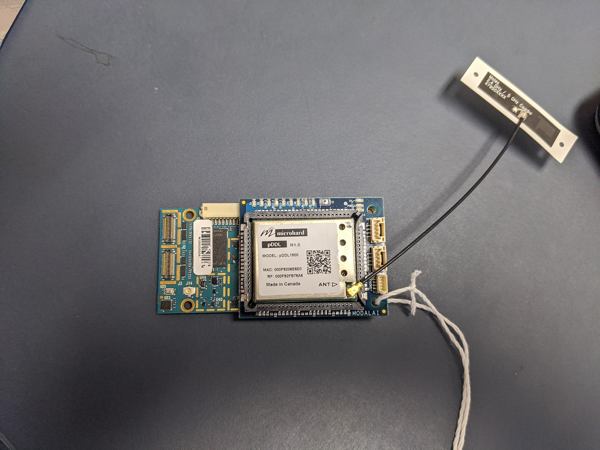
Additional Pictures
Disassembled
Assembled with VOXL