VOXL Time of Flight (ToF) Sensor Datasheet (IRS2975C)
Table of Contents
- VOXL Time of Flight (ToF) Sensor Datasheet (IRS2975C)
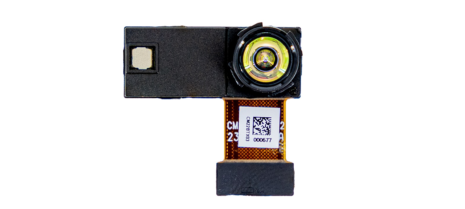
The PMD Time of Flight sensor produces high-fidelity depth mapping indoors up to 6m. On the VOXL platform this sensor is mutually exclusive to the stereo cameras, meaning the stereo cameras need to be replaced with the TOF Add-on.
The M0169-1 ToF adapter has the M0040-1 backwards compatible Panasonic AXT connector, but requires external 5V power. The M0169-1 adapter can be used with the M0036-1 or M0074-1 extension flexes to connect to VOXL 2.
The M0178-1 adapter does not require external power, but is exclusive to VOXL 2.
Specification
MSU-M0169-1-01 106° FOV
| Specification | Value |
|---|---|
| Part Number | MSU-M0169-1-01 |
| Technology | PMD |
| Rate | 5 - 45FPS in configurable option modes for distance / accuracy / framerate |
| Exposure Time | 4.8 ms typ. @ 45 fps / 30 ms typ. @ 5 fps |
| Resolution | 240 x 180 px |
| FOV (H x W) | 106° x 86°, 138.4° DFOV Max |
| Range | 4 - 6m |
| Illumination | 940nm |
| Depth Resolution | TBD |
| Time Sync | No physical pin, but the frame timestamp is measured with 50ns precision on a single clock. All of the sensors on the VOXL platform are timestamped for computer vision. |
| Power Consumption | TBD |
| Weight | TBD |
| Dimensions | TBD |
| Eye Safe | Yes |
Requirements
- VOXL (APQ8096) not supported.
- VOXL 2 (QRB5165) Requires SDK 1.2 or greater
Current/Power Consumption
The module draws 1.0-1.2Amp bursts continuously (>5ms pulses occurring rapidly enough to warrant a 2A+ DC/DC on the M0169-1 PCB). The average current draw is 300mA, but the pulses require a dedicated 2A DC/DC for the ToF module to work. Consequently, the DC/DC converter on M0169-1 requires 4-5V with at least 1.4-1.5A+ to account for cable losses and efficiencies.
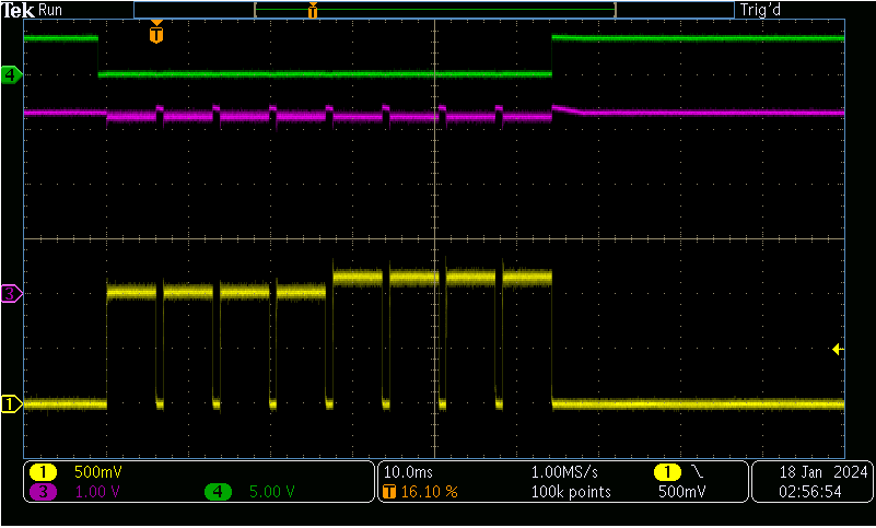
- Yellow: VCSEL current draw (1A/1V)
- Green : VCSEL enable signal (turns on the emitter at the beginning of exposure)
- Purple: VCSEL supply voltage (3.30V in off state, sags to 3.25V during bursts, likely cable losses in test setup)
Technical Drawings
3D STEP File
2D Diagram
Module Connector Pinout
Connector Specs
| VOXL Board Connector | M0169-1 J? Mating Connector |
|---|---|
| Panasonic, MPN: AXT336124 | Panasonic MPN: AXT436124 |
Pin-out
| Pin # | Signal Name | Pin # | Signal Name |
|---|---|---|---|
| 1 | GND | 2 | GND |
| 3 | VREG_L17A_2P8 (AFVDD) | 4 | CAM0_STANDBY_N |
| 5 | CCI_I2C_SDA0 | 6 | VREG_LVS1A_1P8 (DOVDD) |
| 7 | CCI_I2C_SCL0 | 8 | VREG_L3A_1P1 (DVDD) |
| 9 | CAM0_RST0_N | 10 | CAM_MCLK0_BUFF |
| 11 | GND | 12 | GND |
| 13 | MIPI_CSI0_CLK_CONN_P | 14 | CAM_FLASH |
| 15 | MIPI_CSI0_CLK_CONN_M | 16 | CAM_SYNC_0 |
| 17 | MIPI_CSI0_LANE0_CONN_P | 18 | CAM0_MCLK3 |
| 19 | MIPI_CSI0_LANE0_CONN_M | 20 | VREG_L22A_2P8 (AVDD) |
| 21 | GND | 22 | GND |
| 23 | MIPI_CSI0_LANE1_CONN_P | 24 | CAM_RST1_N |
| 25 | MIPI_CSI0_LANE1_CONN_M | 26 | CAM_SYNC_1 |
| 27 | MIPI_CSI0_LANE2_CONN_P | 28 | CCI_I2C_SDA1 |
| 29 | MIPI_CSI0_LANE2_CONN_M | 30 | CCI_I2C_SCL1 |
| 31 | GND | 32 | GND |
| 33 | MIPI_CSI0_LANE3_CONN_P | 34 | VPH_PWR |
| 35 | MIPI_CSI0_LANE3_CONN_M | 36 | GND |
VOXL Integration
Hardware Design Guidance
VOXL SDK
This guide assumes that you are able to run commands on VOXL2; if you cannot, please see VOXL Developer Bootcamp. All commands specified below should be run on VOXL2.
Supported Sensor Module
- M0169-1 IRS2975C Module (Requires VOXL SDK >= v1.2)
Camera Server Configuration
IRS2975C support is coming to VOXL camera server in VOXL SDK release 1.2
In order to set up your VOXL2 to use just the IRS2975C ToF sensor, connect the camera to the J6 Lower camera connector (it must have ID 0; for more details, see VOXL2 Camera Configs). Then, run voxl-configure-cameras 24 in order to configure VOXL camera server to use the M0169-1 ToF sensor.
If you wish to use any of the pre-existing M0040-1 ToF configurations listed in the VOXL2 Camera Configs page, first run voxl-configure-cameras <id>, where <id> is the ID number of the configuration you wish to use. Then, edit the VOXL Camera Server configuration file on VOXL2 (/etc/modalai/voxl-camera-server.conf) and replace the line containing "type": "pmd-tof", with "type": "pmd-tof-liow2",. You have now updated a legacy M0040-1 ToF configuration to function with the newer M0169-1 module.
After performing either of the above procedures, please reboot VOXL2 in order to reload the VOXL camera server configuration. To verify functionality, please see the VOXL Portal section below.
VOXL Portal
In order to verify the functionality of your ToF configuration, you can attempt to view the IR and depth map images in VOXL portal. In order to view VOXL portal, your VOXL should be connected to the internet (see VOXL2 WiFi Setup).
After your VOXL is connected to the internet, run systemctl status voxl-portal. Then, find the IP address of your VOXL using hostname -I and visit this address in the web browser of a computer connected to the same local network as your VOXL (or your VOXL’s access point, in AP mode). Then, navigate to “Cameras > TOF Conf / Depth / IR” in the top navigation bar, and verify that the displayed video stream matches what the camera is pointed at.