VOXL 2 Connecting an External Flight Controller
Table of contents
- Summary
- VOXL-SDK Integration
- UART Devices
- Add-On Boards
- VOXL SDK Software Setup
- pymavlink Software Based Example
Summary
VOXL 2 is a great companion computer for PX4 and ArduPilot. Although VOXL 2 has the capability to run PX4 in a real time DSP, some use cases call for an external flight controller.
You can communicate between a flight controller TELEM port and a VOXL 2 UART port. For example, Flight Core has a default telemetry port on J5 with a MavLINK instance running at 57600 baud.
VOXL-SDK Integration
Available starting in SDK 1.1.0
The libqrb5165-io library can be used to interface with the UARTs. Using the Applications Process UARTs, you can follow standard Linux paradigms. Using the DSP UARTs, you need to use the libqrb5165-io library.
If you are interfacing via MAVLink, it’s recommended to use the voxl-mavlink-server project, which depends on libqrb5165-io and shows usage.
UART Devices
Application Processor UARTs
As of SDK 1.0.0 (System Image 1.6), there are 4 applications processor UARTs exposed on VOXL 2, which can be used using standard Linux techniques.
| UART | Connector | Add-On / Adapter | libqrb5165-io ID/enum |
|---|---|---|---|
/dev/ttyHS0 | J8, camera group 2 | M0076 with hand soldering to test points | 0, APPS_HS0_UART |
/dev/ttyHS1 | J3, Board to Board | M0151 / Purchase Here | 1, APPS_HS1_UART |
/dev/ttyHS2 | J5, HS Board to Board | M0090 / Purchase Here | 2, APPS_HS2_UART |
/dev/ttyHS3 | J5, HS Board to Board | M0130 - Internal Use | 3, APPS_HS3_UART |
As of SDK 1.1.0+ (System Image 1.7.1), on VOXL 2 Mini, there is 1 applications processor UART exposed
| UART | Connector | libqrb5165-io ID/enum |
|---|---|---|
/dev/ttyHS0 | J10, pins 4/5 (TX/RX) | 0, APPS_HS0_UART |
DSP UARTs (via Apps Proc)
Available starting in SDK 1.1.0
NOTE1: at this time, only one of these QUPX UARTs can be used at a time
NOTE2: if running voxl-px4, these DSP UARTs aren’t available
Additionally, through the libqrb5165-io project, you can access the DSP UARTs from the applications processor as well, the the board-to-cable interfaces (no add on board required!).
| UART | Connector | libqrb5165-io ID/enum |
|---|---|---|
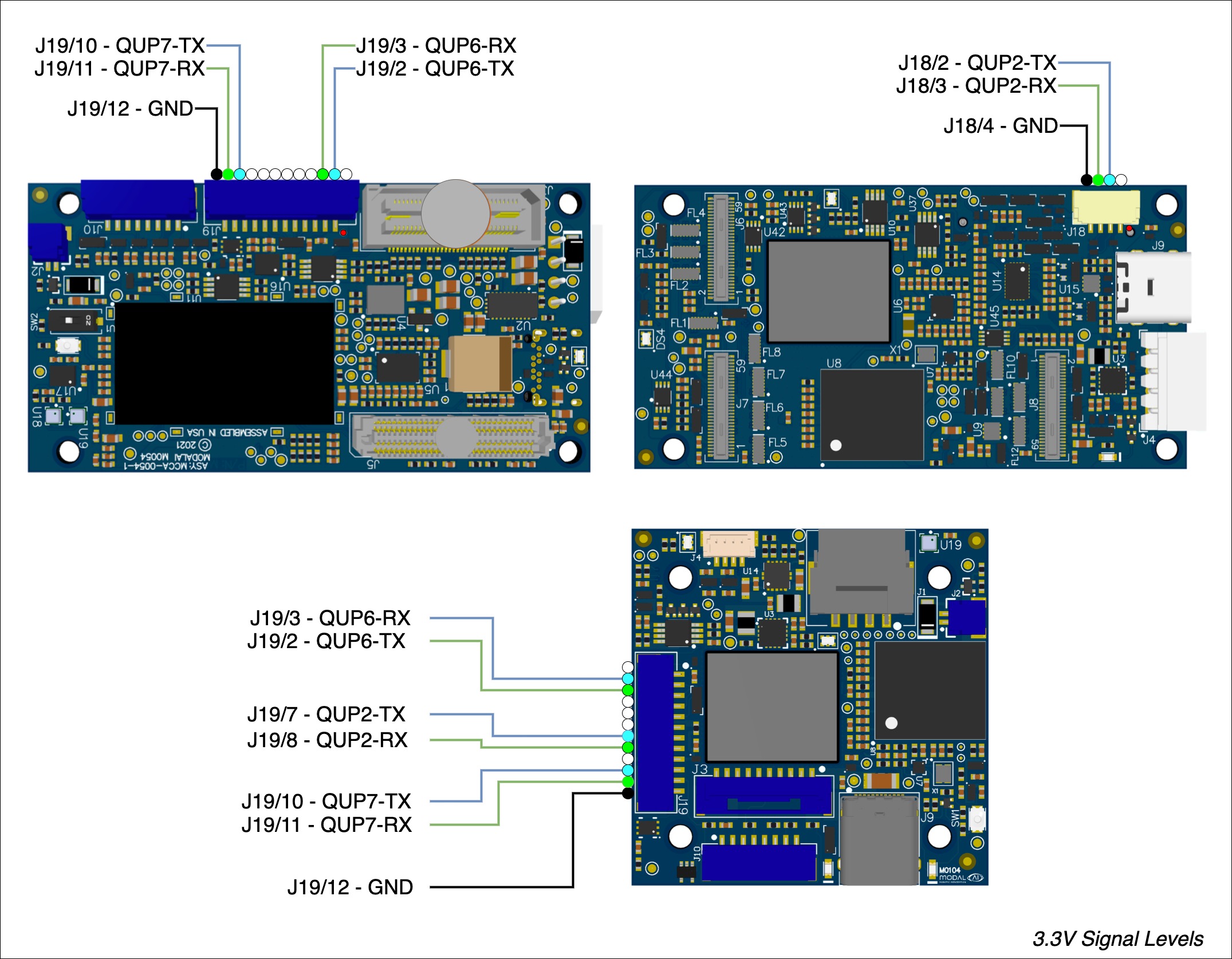
QUP2 | VOXL2 J18, VOXL2 Mini J19 pin 7/8, ESC Port | 12, SLPI_QUP2_UART |
QUP6 | J19 pin 2/3, GNSS Port | 16, SLPI_QUP6_UART |
QUP7 | J19 pin 10/11, RC IO Port | 17, SLPI_QUP7_UART |
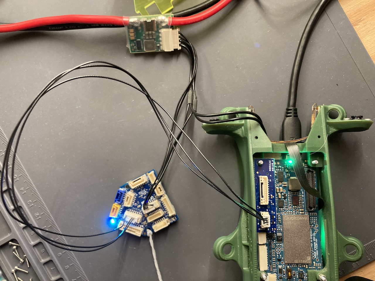
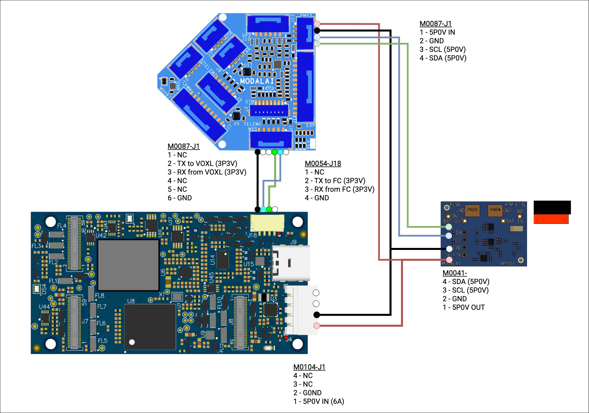
DSP UART to Flight Core v2
Add-On Boards
Using USB/UART Addon Board (M0125 or M0151)
In the following example, we’ll add the USB3/UART Add-On Board (M0125) to VOXL 2 (M0054) which gives us a 4 pin JST GH connector with a UART available at /dev/ttyHS1 from the applications processor.
Using MCBL-00067-1, connect from M0151’s J3 to Flight Core’s (v1/v2) (M0018/M0087) J5, TELEM1/TELEM2 (respectively).
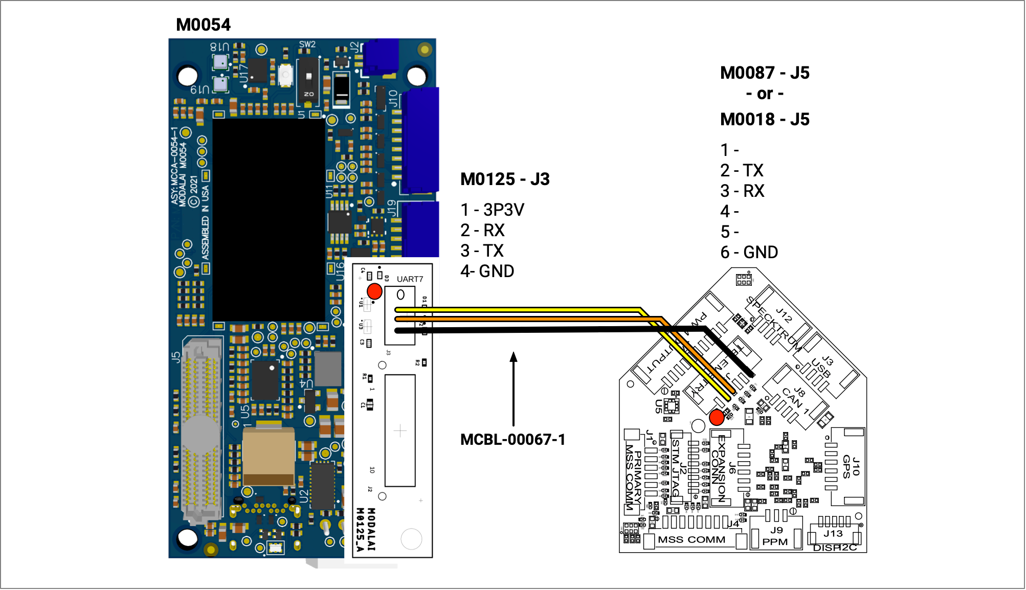
| M0125 or M0151 J3 | M0018 J5 |
|---|---|
| 1 | |
| 2 RX | 2 TX |
| 3 TX | 3 RX |
| 4 GND | 6 GND |
Using M.2 5G Modem Addon Board (M0090)
The VOXL2 (M0054) can have the M.2 5G Modem Board Addon attached, which exposes a UART on M0090 - J9 that is accessible in VOXL2’s application processor as /dev/ttyHS2.
Using MCBL-00066-1, connect from M0090’s J9 to Flight Core’s (v1/v2) (M0018/M0087) J5, TELEM1/TELEM2 (respectively).
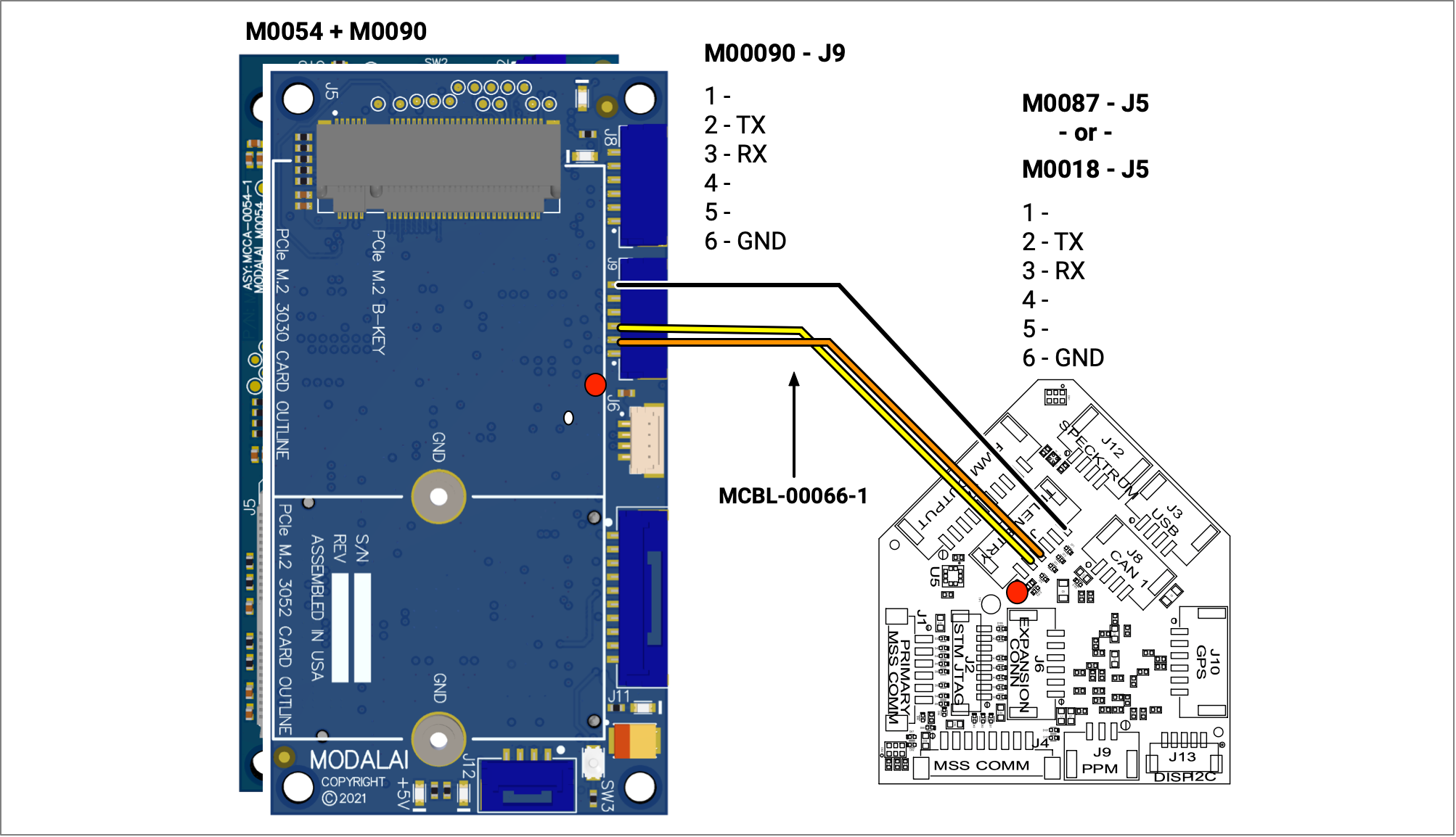
| M0090 J9 | M0018 J5 |
|---|---|
| 1 | |
| 2 TX | 3 RX |
| 3 RX | 2 TX |
| 4 | |
| 5 | |
| 6 | 6 GND |
Using J8 Camera Connector
You will need to use a level shifter likely, as the logic is 1.8V here. VOXL2’s camera group 3 connector can be used with M0076 interposer which has test points you can solder to.
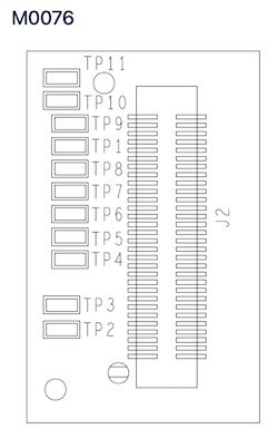
- UART_TX - TP7
- UART_RX - TP8
- VREF 1P8 - TP1
- DGND - TP11
VOXL SDK Software Setup
For information on MAVlink routing in VOXL-SDK please see here.
autopilot_uart_bus Values
voxl-mavlink-server ships in the VOXL SDK, with a config file located at /etc/modalai/voxl-mavlink-server.conf. For the autopilot_uart_bus field, these are current options:
| ENUM | Device / Name | autopilot_uart_bus value |
|---|---|---|
APPS_HS0_UART | /dev/ttyHS0 | “autopilot_uart_bus”: 0 |
APPS_HS1_UART | /dev/ttyHS1 | “autopilot_uart_bus”: 1 |
APPS_HS2_UART | /dev/ttyHS2 | “autopilot_uart_bus”: 2 |
APPS_HS3_UART | /dev/ttyHS3 | “autopilot_uart_bus”: 3 |
SLPI_QUP2_UART | QUP2 | “autopilot_uart_bus”: 12 |
SLPI_QUP6_UART | QUP6 | “autopilot_uart_bus”: 16 |
SLPI_QUP7_UART | QUP7 | “autopilot_uart_bus”: 17 |
autopilot_uart_bus Values
For autopilot_uart_bus, configure this the same as the MAVLink instance on Flight Core. In this example, we are using 921600.
For en_external_uart_ap, set to true.
For apps proc, standard termios rates up to 4000000.
For DSP, a bit more custom rates:
9600, 38400, 57600, 115200, 230400, 250000, 420000, 460800, 921600, 1843200, 2000000
VOXL 2 as Companion Computer PX4 SW Setup
If using Flight Core, you would likely need to connect over the USB interface first to configure the external flight controller.
For this example to work out of the box, make sure to set SER_TELX_BAUD to the default baud rate of 921600 if you’ve changed it.
- Connect to QGroundControl over USB and open the parameters.
- On Flight Core v1 (M0018)
- J1 is mapped to
TELEM2in PX4 (/dev/ttyS4), useSER_TEL2_BAUD - J4 is mapped to
TELEM3in PX4 (/dev/ttyS4), useSER_TEL3_BAUD. This is used by ModalAI ESCs by default. - J5 is mapped to
TELEM1in PX4 (/dev/ttyHS6), useSER_TEL1_BAUD
- J1 is mapped to
- On Flight Core v2 (M0087)
- J1 is mapped to
TELEM1in PX4 (/dev/ttyHS6), useSER_TEL1_BAUD - J5 is mapped to
TELEM2in PX4 (/dev/ttyHS4), useSER_TEL2_BAUD. This is used by ModalAI ESCs by default.
- J1 is mapped to
- On Flight Core v1 (M0018)
Check the status of MAVLink instances by opening the MAVLink Console in QGC and running mavlink status:
On Flight Core v1, you should see something like this if using 921600 baud:
instance #1:
    mavlink chan: #1
    type:        GENERIC LINK OR RADIO
    flow control: ON
    rates:
      tx: 81.8 B/s
      txerr: 0.0 B/s
      tx rate mult: 0.682
      tx rate max: 1200 B/s
      rx: 20.9 B/s
      rx loss: 0.0%
      received from sysid: 0 compid: 197: 43, lost: 0, last 343 ms ago
    FTP enabled: YES, TX enabled: YES
    mode: Normal
    MAVLink version: 2
    transport protocol: serial (/dev/ttyS6 @921600)
Above is showing you that the Flight Core is communicating with VOXL2 successfully, note tx: 81.8 B/s and rx: 20.9 B/s rates indicate bidirectional traffic.
VOXL 2 as Companion Computer ArduPilot SW Setup
TBD
ArduPilot pull request for VOXL-compatible Visual Inertial Odometry support Github
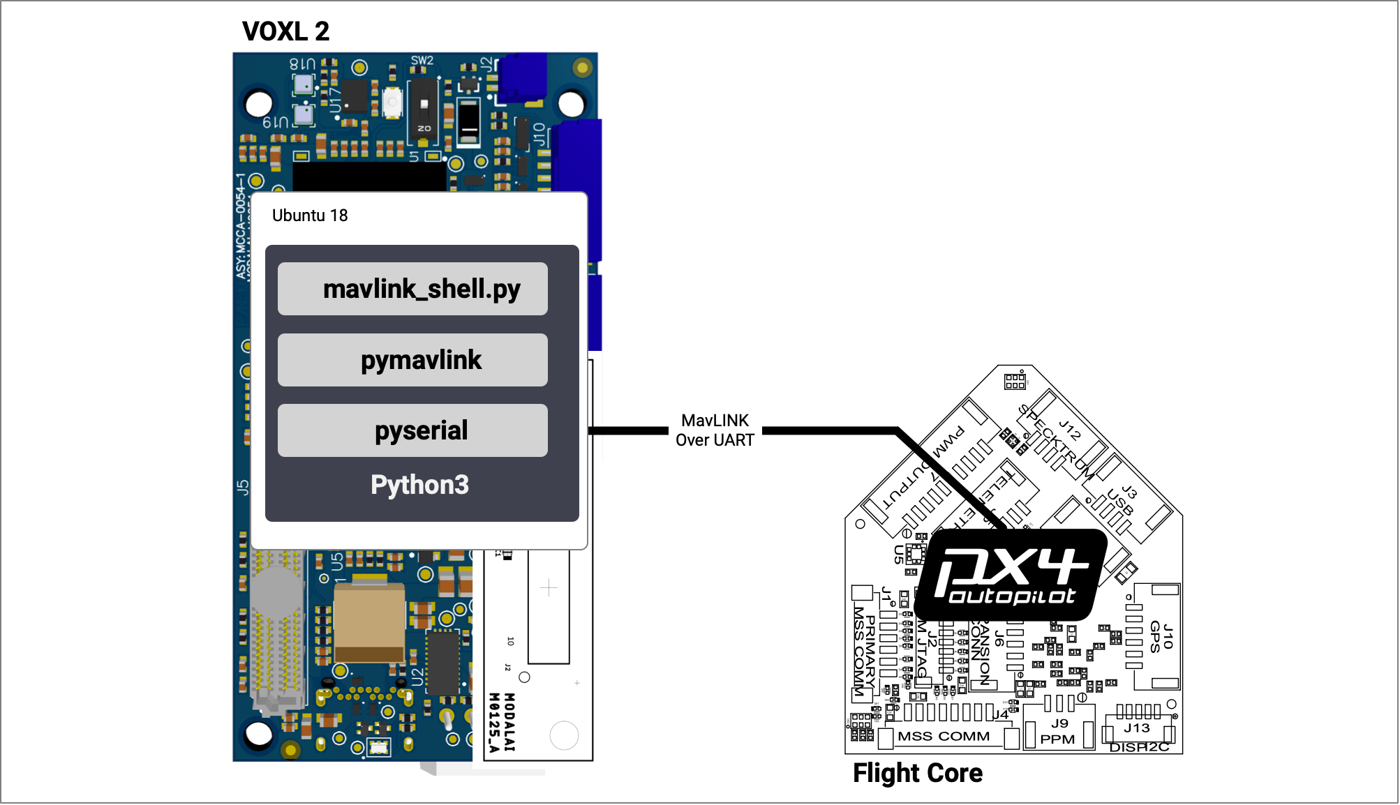
pymavlink Software Based Example
This clashes with the example above, so ensure to disable the
voxl-mavlink-serverif you configured the VOXL SDK.
The SER_TEL1_BAUD/SER_TEL1_BAUD baud rate should be set to 57600 for thi example (for Flight Core v1/v2 respectively).
First, connect VOXL 2 to the internet so we can use apt to install pymavlink. You can connect an ethernet or WiFi dongle to the USB3 port.
Conect to the VOXL 2 over ADB:
adb shell
Now on target:
apt update
sudo apt-get install python3-pip
sudo apt-get install libxml2-dev libxslt-dev python-dev
sudo pip3 install pymavlink pyserial
Get the mavlink_shell.py tool from PX4:
cd /home
wget https://raw.githubusercontent.com/PX4/PX4-Autopilot/main/Tools/mavlink_shell.py
Now, run the program and interact with the Flight Core.
python3 mavlink_shell.py /dev/ttyHS1
Connecting to MAVLINK...

NuttShell (NSH)

nsh> ver all

HW arch: MODALAI_FC_V1
HW type: V106
HW version: 0x00000000
HW revision: 0x00000006
FW git-hash: 7008425b466eba94e35304e502454208d578ba56
FW version: 1.11.3 0 (17498880)
FW git-branch: fcio-v2
OS: NuttX
OS version: Release 8.2.0 (134349055)
OS git-hash: ec20f2e6c5cc35b2b9bbe942dea55eabb81297b6
Build datetime: May 10 2022 18:38:31
Build uri: localhost
Toolchain: GNU GCC, 9.3.1 20200408 (release)
PX4GUID: 0002000000003930353534385109003a002e
MCU: STM32F76xxx, rev. Z