VOXL Flight Connectors
Due to supply chain issues, the colors of the connectors on VOXL Flight are subject to change. If the colors of the connectors are different, please disregard.
Table of contents
- Board Connections and Pin-out Specifications
- J2 - Hires 4k Image Sensor (CSI0)
- J3 - Stereo or Time-of-flight Image Sensor (CSI1)
- J6 - Cooling Fan Connector
- J7 BLSP6 (I2C) and BLSP9 (UART / SPI): External GPS/MAG
- J13 - Expansion B2B connection
- J14 - Integrated GNSS Antenna Connection
- J1001 - Programming and Debug Console (USART3)
- J1002 - UART ESC, UART2/TELEM3 Interface Connector
- J1003 - PPM RC In
- J1004 - RC input / Spektrum/SBus/USART6 Connector
- J1006 - USB Connector
- J1007 - 8-Channel PWM / 4-Channel DShot ESC Output Connector
- J1008 - CAN Bus Connector
- J1009 - I2C3, UART4
- J1010 - Telemetry Connector (TELEM1)
- J1011 - I2C2, Safety Button Input
- J1012 - External GPS & Mag, USART1, I2C1 Connector
- J1013 - 5V DC Power Input, I2C3 to power cable “APM”
- J4 - Tracking/Optic Flow Image Sensor (CSI2)
- J8 - USB 3.0 OTG
- J10 - UART or I2C off-board (external Sonar or IMU sensor)
- J11 - BLSP12 off-board (SPEKTRUM)
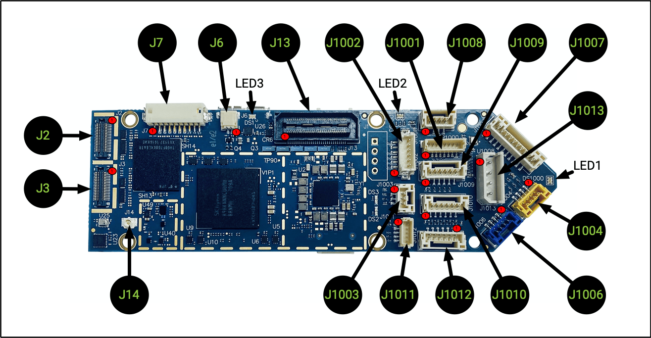
Board Connections and Pin-out Specifications
VOXL Flight Board Top
Note: 1000 Series connectors accessible from the STM32/PX4
| Connector | Summary |
|---|---|
| J2 | Hires 4k Image Sensor (CSI0) |
| J3 | Stereo Image Sensor (CSI1) |
| J6 | Cooling Fan Connector |
| J7 | BLSP6 (GPIO) and BLSP9 (UART) |
| J13 | Expansion B2B |
| J14 | Integrated GNSS Antenna Connection |
| J1001 | Programming and Debug/UART3 |
| J1002 | UART ESC, UART2/TELEM3 |
| J1003 | PPM RC In |
| J1004 | RC Input, Spektrum/SBus/UART6 |
| J1006 | USB 2.0 Connector (PX4/QGroundControl) |
| J1007 | 8-Channel PWM/DShot ESC Output |
| J1008 | CAN Bus |
| J1009 | I2C3, UART4 |
| J1010 | Telemetry (TELEM1) |
| J1011 | I2C2, Safety Button Input |
| J1012 | External GPS & Mag, UART1, I2C1 |
| J1013 | Power Input, I2C3 |
J2 - Hires 4k Image Sensor (CSI0)
| J2 Board Connector | Image Sensor (Flex) Mating Connector |
|---|---|
| Panasonic, MPN: AXT336124 | Panasonic MPN: AXT436124 |
Pin-out:
| Pin # | Signal Name | Pin # | Signal Name |
|---|---|---|---|
| 1 | GND | 2 | GND |
| 3 | VREG_L17A_2P8 (AFVDD) | 4 | CAM0_STANDBY_N |
| 5 | CCI_I2C_SDA0 | 6 | VREG_LVS1A_1P8 (DOVDD) |
| 7 | CCI_I2C_SCL0 | 8 | VREG_L3A_1P1 (DVDD) |
| 9 | CAM0_RST0_N | 10 | CAM_MCLK0_BUFF |
| 11 | GND | 12 | GND |
| 13 | MIPI_CSI0_CLK_CONN_P | 14 | CAM_FLASH |
| 15 | MIPI_CSI0_CLK_CONN_M | 16 | CAM_SYNC_0 |
| 17 | MIPI_CSI0_LANE0_CONN_P | 18 | CAM0_MCLK3 |
| 19 | MIPI_CSI0_LANE0_CONN_M | 20 | VREG_L22A_2P8 (AVDD) |
| 21 | GND | 22 | GND |
| 23 | MIPI_CSI0_LANE1_CONN_P | 24 | CAM_RST1_N |
| 25 | MIPI_CSI0_LANE1_CONN_M | 26 | CAM_SYNC_1 |
| 27 | MIPI_CSI0_LANE2_CONN_P | 28 | CCI_I2C_SDA1 |
| 29 | MIPI_CSI0_LANE2_CONN_M | 30 | CCI_I2C_SCL1 |
| 31 | GND | 32 | GND |
| 33 | MIPI_CSI0_LANE3_CONN_P | 34 | VPH_PWR |
| 35 | MIPI_CSI0_LANE3_CONN_M | 36 | GND |
Supported Sensors
The following sensors are supported on J2 (CSI0):
- IMX214
- IMX230
- IMX377
- IMX378
- OV16825
Supported modules:
| Description | MPN | Link | Datasheet |
|---|---|---|---|
| ModalAI Sony IMX214 wide angle | MCAM-00024 | Buy | Datasheet |
| ModalAI Sony IMX214 | MCAM-00024 | Buy | Datasheet |
| ModalAI Sony IMX377 | MCAM-00026 | Buy | Datasheet |
J3 - Stereo or Time-of-flight Image Sensor (CSI1)
| J3 Board Connector | Image Sensor (Flex) Mating Connector |
|---|---|
| Panasonic, MPN: AXT336124 | Panasonic MPN: AXT436124 |
Pin-out:
| Pin # | Signal Name | Pin # | Signal Name |
|---|---|---|---|
| 1 | GND | 2 | GND |
| 3 | VREG_L18A_2P8 (AFVDD) | 4 | CAM1_STANDBY_N |
| 5 | CCI_I2C_SDA0 | 6 | VREG_S4A_1P8 (DOVDD) |
| 7 | CCI_I2C_SCL0 | 8 | VREG_L3A_1P1 (DVDD) |
| 9 | CAM1_RST0_N | 10 | CAM_MCLK1_BUFF |
| 11 | GND | 12 | GND |
| 13 | MIPI_CSI1_CLK_CONN_P | 14 | CAM_FLASH |
| 15 | MIPI_CSI1_CLK_CONN_M | 16 | CAM_SYNC_0 |
| 17 | MIPI_CSI1_LANE0_CONN_P | 18 | CAM1_MCLK3 |
| 19 | MIPI_CSI1_LANE0_CONN_M | 20 | VREG_L23A_2P8 (AVDD) |
| 21 | GND | 22 | GND |
| 23 | MIPI_CSI1_LANE1_CONN_P | 24 | CAM_RST1_N |
| 25 | MIPI_CSI1_LANE1_CONN_M | 26 | CAM_SYNC_1 |
| 27 | MIPI_CSI1_LANE2_CONN_P | 28 | CCI_I2C_SDA1 |
| 29 | MIPI_CSI1_LANE2_CONN_M | 30 | CCI_I2C_SCL1 |
| 31 | GND | 32 | GND |
| 33 | MIPI_CSI1_LANE3_CONN_P | 34 | VPH_PWR |
| 35 | MIPI_CSI1_LANE3_CONN_M | 36 | GND |
Supported Image Sensors
The following sensors are supported on J3 (CSI1):
- OV7251
- PMD (Infineon)
Supported modules:
| Description | MPN | Link | Datasheet |
|---|---|---|---|
| Stereo Camera Pair for Obstacle Avoidance Kit | MSU-M0015-1-01 | Buy | Datasheet |
| PMD Time of Flight | MKIT-00017-3 | Buy | Datasheet |
J6 - Cooling Fan Connector
Pin Configuration
| Pin # | Signal Name |
|---|---|
| 1 | EXT_FAN_5V |
| 2 | EXT_FAN_RET |
Connector
- J.S.T. Corporation, SM02B-SRSS- TB(LF)(SN)
Mating Connector
VOXL Side:
- J.S.T. Corporation, MPN: SM02B- SRSS-TB(LF)(SN)
Fan Side:
- J.S.T. Corporation
- Connector, MPN: SHR-02V-S
- Connector Contact Pins, MPN: SSH-003T-P0.2-H
Notes
Supported Fan Module:
- DDH Enterprise, Inc, MPN: DDH-2016-013 MCN: 420-59855-0001
J7 BLSP6 (I2C) and BLSP9 (UART / SPI): External GPS/MAG
Pin Configuration
| Pin # | Signal Name | Alt Function |
|---|---|---|
| 1 | VREG_3P3V | |
| 2 | BLSP9_UART_TX_3P3 | GPIO 49 / BLSP9_SPI_MOSI |
| 3 | BLSP9_UART_RX_3P3 | GPIO 50 / BLSP9_SPI_MISO |
| 4 | BLSP6_I2C_SDA_3P3 | GPIO 27 |
| 5 | GND | |
| 6 | BLSP6_I2C_SCL_3P3 | GPIO 28 |
| 7 | BLSP6_AUX2_3P3 | (original docs show GPIO 26, however not functional) |
| 8 | BLSP6_AUX1_3P3 | (original docs show GPIO 25, however not functional) |
| 9 | BLSP9_UART_CTS_N_3P3 | GPIO 51 / BLSP9_SPI_CS_N |
| 10 | BLSP9_UART_RFR_N_3P3 | GPIO 52 / BLSP9_SPI_CLK |
Connector
- HIROSE Electric, MPN: DF13-10P-1.25H
Mating Connector
VOXL Side:
- HIROSE Electric, MPN: DF13- 10P-1.25H
GPS/MAG Side:
- HIROSE Electric, MPN: DF13- 10S-1.25C
Notes
Supported GPS Module:
- MCN: 20-CE766-H1 = CCA, H13931V2, SIRFSTARV CREST BOARD REV2
The above uses antenna:
- TAOGLAS LTD, MPN: CGGBP.25.4.A.02
J13 - Expansion B2B connection
Pin Configuration
| Pin # | Signal Name | Pin # | Signal Name |
|---|---|---|---|
| 1 | GND | 2 | VDCIN_5V_CONN |
| 3 | APQ_GPIO_96 | 4 | VDCIN_5V_CONN |
| 5 | APQ_GPIO_95 | 6 | VDCIN_5V_CONN |
| 7 | APQ_GPIO_94 | 8 | USB2_HS_ID |
| 9 | APQ_GPIO_92 | 10 | GND |
| 11 | GND | 12 | USB2_HS_D_M |
| 13 | BLSP11_0_SCL_GPIO61 | 14 | USB2_HS_D_P |
| 15 | BLSP11_1_SDA_GPIO60 | 16 | USB2_HS_VBUS_CONN |
| 17 | BLSP11_2_RX_GPIO59 | 18 | GND |
| 19 | BLSP11_3_TX_GPIO58 | 20 | APQ_GPIO_64 |
| 21 | GND | 22 | APQ_GPIO_127 |
| 23 | BLSP8_0_SCL_GPIO7 | 24 | APQ_GPIO_126 |
| 25 | BLSP8_1_SDA_GPIO6 | 26 | APQ_GPIO_70 |
| 27 | BLSP8_2_RX_GPIO5 | 28 | APQ_GPIO_71 |
| 29 | BLSP8_3_TX_GPIO4 | 30 | APQ_GPIO_72 |
| 31 | GND | 32 | APQ_GPIO_93 |
| 33 | JTAG_TDO | 34 | APQ_GPIO_91 |
| 35 | JTAG_SRST_N | 36 | GND |
| 37 | JTAG_TCK | 38 | APQ_GPIO_106 |
| 39 | JTAG_TDI | 40 | APQ_GPIO_107 |
| 41 | JTAG_TMS | 42 | APQ_GPIO_108 |
| 43 | JTAG_TRST_N | 44 | GND |
| 45 | JTAG_PS_HOLD | 46 | APQ_GPIO_114 |
| 47 | VREG_S4A_1P8 | 48 | APQ_GPIO_104 |
| 49 | PMIC_RESIN_N | 50 | APQ_GPIO_103 |
| 51 | APQ_RESOUT_N | 52 | APQ_GPIO_102 |
| 53 | VREG_3P3V | 54 | APQ_GPIO_101 |
| 55 | KYPDPWR_N | 56 | APQ_GPIO_57 |
| 57 | VPH_PWR | 58 | GND |
| 59 | GND | 60 | PM8996_GPIOC15 |
Connector
- Samtec Inc., MPN: QSH-030-01-L-D-A-K
Mating Connector
VOXL Side:
- Samtec Inc., MPN: QSH-030-01-L-D-A-K
Debug Board Side:
- Samtec Inc, MPN: QTH-030-02- L-D-A-K
Notes
Supported Debug B2B Module:
- Eagle Nest, MCN: 20-H9420-1
- Serial Feather PRO Edition, MCN: 30-H9916-1
More details are available here.
J14 - Integrated GNSS Antenna Connection
Pin Configuration
- Center Conductor
Connector
- HIROSE Electric, MPN: U.FL-R- SMT-1(10)
Mating Connector
VOXL Side:
- HIROSE Electric, MPN: U.FL-R- SMT-1(10)
GNSS Antenna Side:
- HIROSE Electric, MPN: U.FL-LP
Notes
Supported Module:
- CABLE ASSY, U.FL TO SMA-F BHD, 1.32 MM COAX MCN: CV90-N5175-A4
- Passive antenna configuration (no DC bias)
J1001 - Programming and Debug Console (USART3)
Connector: 8 Position, Vertical, BM08B-SRSS-TB(LF)(SN)
Note: used for PX4 debug console, can be used for STM32 FW update
| Pin # | Signal Name |
|---|---|
| 1 | VREG_3V3 |
| 2 | USART3_2W_DEBUG_TX |
| 3 | USART3_2W_DEBUG_RX |
| 4 | SWDIO |
| 5 | SWCLK |
| 6 | GND |
| 7 | !RESET |
| 8 | VPP_STM |
J1002 - UART ESC, UART2/TELEM3 Interface Connector
Connector: 6 Position DF13, Vertical, DF13-6P-1.25V(50)
Note: 2 wire UART is OK here
| Pin # | Signal Name |
|---|---|
| 1 | 5VDC (other pins are 3.3V, input or output if supplied at another pin) |
| 2 | UART2_4W_RX_3V3 |
| 3 | UART2_4W_TX_3V3 |
| 4 | UART2_4W_RTS_3V3 |
| 5 | GND |
| 6 | UART2_4W_CTS_3V3 |
J1003 - PPM RC In
Connector: 3 Position JST GH, Vertical, BM03B-GHS-TBT
Note: This JST connector is reversed when compared to Flight Core, pinouts are still the same
| Pin # | Signal Name |
|---|---|
| 1 | 5VDC (other pins 3.3V, input or output if supplied at another pin) |
| 2 | PPM_IN |
| 3 | GND |
J1004 - RC input / Spektrum/SBus/USART6 Connector
Connector: 4 Position JST GH, Vertical, BM04B-GHS-TBT
Note: For SBus receievers (e.g. FrSky X8R), power off 5VDC from another port
| Pin # | Signal Name |
|---|---|
| 1 | VREG_3V3 (Spektrum Power) |
| 2 | USART6_TX |
| 3 | SPEKTRUM RX (3.3V), SBus RX (3.3V), USART6_RX |
| 4 | GND |
J1006 - USB Connector
USB connection for PX4 only (doesn’t not connect to VOXL/Linux).
This connector does not provide system power! The system pulls more that 500mA and thus can’t be powered from USB!
Connector: BLUE 4 Position JST GH, Vertical, BM04B-GHS-TBT
| Pin # | Signal Name |
|---|---|
| 1 | VBUS_IN |
| 2 | DATA_M |
| 3 | DATA_P |
| 4 | GND |
J1007 - 8-Channel PWM / 4-Channel DShot ESC Output Connector
Connector: 10 Position JST GH, Vertical, BM10B-GHS-TBT
5V is for Ref Only
| Pin # | Signal Name |
|---|---|
| 1 | 5VDC (other pins are 3.3V, input or output if supplied at another pin) |
| 2 | PWM_CH1 |
| 3 | PWM_CH2 |
| 4 | PWM_CH3 |
| 5 | PWM_CH4 |
| 6 | PWM_CH5 |
| 7 | PWM_CH6 |
| 8 | PWM_CH7 |
| 9 | PWM_CH8 |
| 10 | GND |
J1008 - CAN Bus Connector
Connector: 4 Position JST GH, Vertical, BM04B-GHS-TBT
| Pin # | Signal Name |
|---|---|
| 1 | 5VDC |
| 2 | CANH* |
| 3 | CANL* |
| 4 | GND |
*CAN signals are compliant with ISO 11898-2:2016 and SAE J2284-1 to SAE J2284-5
J1009 - I2C3, UART4
Connector: 6 Position JST GH, Vertical, BM06B-GHS-TBT
| Pin # | Signal Name |
|---|---|
| 1 | 5VDC (other pins 3.3V, input or output if supplied at another pin) |
| 2 | UART4_2W_TX_3V3 |
| 3 | UART4_2W_RX_3V3 |
| 4 | EXP_I2C3_SCL |
| 5 | EXP_I2C3_SDA |
| 6 | GND |
J1010 - Telemetry Connector (TELEM1)
Connector: 6 Position JST GH, Vertical, MB06B-GHS-TBT
| Pin # | Signal Name |
|---|---|
| 1 | 5VDC (other pins 3.3V, input or output if supplied at another pin) |
| 2 | UART_4W_TX_3V3 |
| 3 | UART_4W_RX_3V3 |
| 4 | UART_4W_CTS_3V3 |
| 5 | UART_4W_RTS_3V3 |
| 6 | GND |
J1011 - I2C2, Safety Button Input
Connector: 5 Position, Vertical, BM05B-SRSS-TB(LF)(SN)
| Pin # | Signal Name |
|---|---|
| 1 | VREG_3V3 |
| 2 | GND |
| 3 | I2C2_SDA |
| 4 | I2C2_SCL |
| 5 | Safety Switch In (switch should pull high to 3.3V to enable) |
J1012 - External GPS & Mag, USART1, I2C1 Connector
Connector: 6 Positiom JST GH, Vertical, BM06B-GHS-TBT
| Pin # | Signal Name |
|---|---|
| 1 | 5VDC (other pins 3.3V, input or output if supplied at another pin) |
| 2 | EXT_GPS_USART1_2W_TX |
| 3 | EXT_GPS_USART1_2W_RX |
| 4 | EXT_GPS_I2C1_SCL |
| 5 | EXT_GPS_I2C1_SDA |
| 6 | GND |
J1013 - 5V DC Power Input, I2C3 to power cable “APM”
Note: This is the main power input and power monitoring connector. See Power Modules
Pin Configuration
| Pin # | Signal Name |
|---|---|
| 1 | 5V DC |
| 2 | GND |
| 3 | I2C3_SCL |
| 4 | I2C3_SDA |
Connector
- Molex Inc, MPN: 22-05-7045
Mating Connector
- 50-37-5043 based cables
Notes
- I2C3 is at 5V CMOS with 10K pull-ups.
- Connect to provided power cable for proper operation and current handling.
Supported Modules
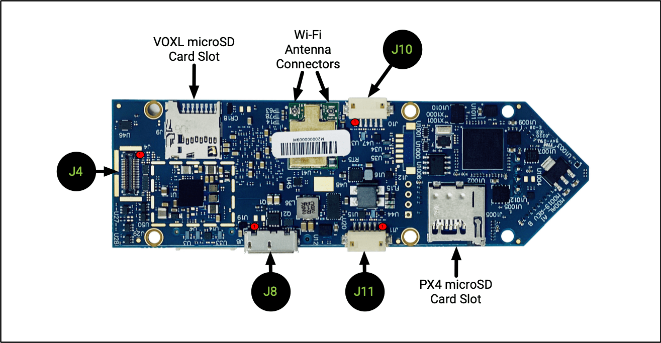
VOXL Flight Board Bottom
Note: 1000 Series connectors accessible from the STM32/PX4
| Connector | Summary |
|---|---|
| J4 | Tracking/Optic Flow Image Sensor (CSI2) |
| J8 | USB 3.0 OTG (ADB) |
| J10 | BLSP7 UART and I2C off-board |
| J11 | BLSP12 UART and I2C off-board |
| VOXL microSD | |
| PX4 microSD | 32Gb Max |
| Wi-Fi Antennas | Included in Kit Molex 1461531100 |
J4 - Tracking/Optic Flow Image Sensor (CSI2)
| J4 Board Connector | Image Sensor (Flex) Mating Connector |
|---|---|
| Panasonic, MPN: AXT336124 | Panasonic MPN: AXT436124 |
Pin-out:
| Pin # | Signal Name | Pin # | Signal Name |
|---|---|---|---|
| 1 | GND | 2 | GND |
| 3 | VREG_L29A_2P8 (AFVDD) | 4 | CAM2_STANDBY_N |
| 5 | CCI_I2C_SDA0 | 6 | VREG_LVS1A_1P8 (DOVDD) |
| 7 | CCI_I2C_SCL0 | 8 | VREG_L3A_1P1 (DVDD) |
| 9 | CAM2_RST0_N | 10 | CAM_MCLK2_BUFF |
| 11 | GND | 12 | GND |
| 13 | MIPI_CSI2_CLK_CONN_P | 14 | CAM_FLASH |
| 15 | MIPI_CSI2_CLK_CONN_M | 16 | CAM_SYNC_0 |
| 17 | MIPI_CSI2_LANE0_CONN_P | 18 | CAM2_MCLK3 |
| 19 | MIPI_CSI2_LANE0_CONN_M | 20 | VREG_L23A_2P8 (AVDD) |
| 21 | GND | 22 | GND |
| 23 | MIPI_CSI2_LANE1_CONN_P | 24 | CAM_RST1_N |
| 25 | MIPI_CSI2_LANE1_CONN_M | 26 | CAM_SYNC_1 |
| 27 | MIPI_CSI2_LANE2_CONN_P | 28 | CCI_I2C_SDA1 |
| 29 | MIPI_CSI2_LANE2_CONN_M | 30 | CCI_I2C_SCL1 |
| 31 | GND | 32 | GND |
| 33 | MIPI_CSI2_LANE3_CONN_P | 34 | VPH_PWR |
| 35 | MIPI_CSI2_LANE3_CONN_M | 36 | GND |
Supported Image Sensors
The following sensors are supported on J4 (CSI2):
- OV7251
Supported modules:
| Description | MPN | Link | Datasheet |
|---|---|---|---|
| Sunny MD102A w/ MSU-M0008-1-01 Adapter | MSU-M0072-1-01 | Buy | |
| ModalAI 166-degree OV7251 B&W VGA Global Shutter | MSU-M0014-1-01 | Buy |
J8 - USB 3.0 OTG
Pin Configuration
| Pin # | Signal Name |
|---|---|
| 1 | VBUS |
| 2 | D- |
| 3 | D+ |
| 4 | ID |
| 5 | GND |
| 6 | MICA_SSTX- |
| 7 | MICA_SSTX+ |
| 8 | GND_DRAIN |
| 9 | MICA_SSRX- |
| 10 | MICA_SSRX+ |
Connector
- KYCON, MPN: KMMX- AB10- SMT1SB30
Mating Connector
- Micro A/B Plug
Notes
- Host mode (e.g. connect a supported USB 3.0 device) requires Micro-A Plug to STD-A in order to get 3.0 SS Functionality. Example cable: Amphenol RUB30-0075 (contact ModalAI for details, available as MCBL-00019-1)
- Host mode USB 2.0 - example cable
J10 - UART or I2C off-board (external Sonar or IMU sensor)
Pin Configuration
| Pin # | Signal Name | Alt Function |
|---|---|---|
| 1 | VREG_3P3V | |
| 2 | SONAR_UART_TX_3P3 | GPIO 53 |
| 3 | SONAR_UART_RX_3P3 | GPIO 54 |
| 4 | EXT_IMU_I2C_SDA_3P3 | GPIO 55 |
| 5 | GND | |
| 6 | EXT_IMU_I2C_SCL_3P3 | GPIO 56 |
Connector
- HIROSE Electric, MPN: DF13-6P-1.25H(50)
Mating Connector
- DF13-6S-1.25C cable assemblies
Notes
- UART and I2C are at 3.3V CMOS levels.
- Connect TX to target device’s RX, and vice-versa.
- I2C has 10K pull-ups.
J11 - BLSP12 off-board (SPEKTRUM)
Pin Configuration
| Pin # | Signal Name | Alt Function |
|---|---|---|
| 1 | VREG_3P3V_SPEKTRUM | |
| 2 | BLSP12_UART_TX_3P3 | GPIO 85 |
| 3 | BLSP12_UART_RX_3P3 | GPIO 86 |
| 4 | BLSP12_I2C_SDA_3P3 | GPIO 87 |
| 5 | GND | |
| 6 | BLSP12_I2C_SCL_3P3 | GPIO 88 |
Connector
- Hirose Electric, MPN: DF13-6P-1.25H(50)
Mating Connector
- DF13-6S-1.25C cable assemblies
Notes
- UART and I2C are at 3.3V CMOS levels.
- Connect TX to target device’s RX, and vice-versa.
- I2C has 10K pull-ups.
Wi-Fi Antenna Connectors (2)
Function
- External Wi-Fi antenna connections
Pin Configuration
- Center Conductor
Connector
- IPEX, MPN: 20449-001E (MHF-4)
Mating Connector
Supported Antennas
Notes
- ANT #1 is for WLAN/BT
- ANT #2 is for WLAN only