VOXL 2 Linux User Guide
Table of contents
UARTs
The following is accurate as of System Image 1.6.
Overview
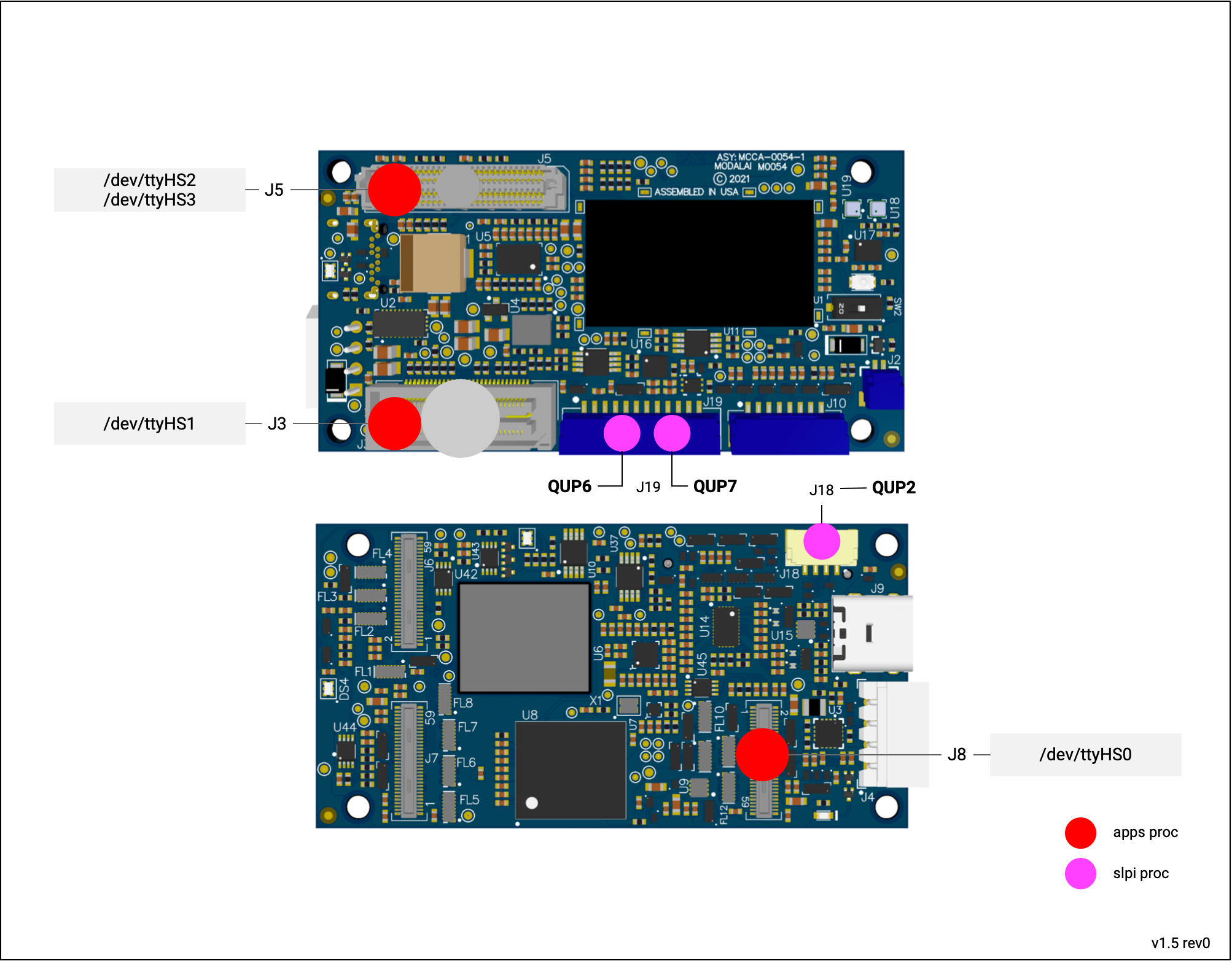
Apps Proc
/dev/ttyHS0 - Camera Group 2 UART
| Device | /dev/ttyHS0 |
| Pins | J8 Pins 38/40 (Tx/Rx) |
| Voltage | 1.8V, directly connected to QRB5165, likely need to level shift |
| Code Sample | TODO |
| Add-Ons | NA |
/dev/ttyHS1 - B2B Connector UART
| Device | /dev/ttyHS1 |
| Pins | J3 Pins 3/5 (Rx/Tx) |
| Voltage | 1.8V, directly connected to QRB5165, likely need to level shift |
| Code Sample | TODO |
| Add-Ons | M0125 J3 Pins 2/3 (Rx/Tx) M0144 JP1 pins 9/11 (Tx/Rx) M0130 J5 Pnis 2/3 (Tx/Rx) |
/dev/ttyHS2 - HSB2B Connector UART
| Device | /dev/ttyHS2 |
| Pins | J5 HS B2B pins 48/49 (Rx/Tx) |
| Voltage | 1.8V, directly connected to QRB5165, likely need to level shift |
| Code Sample | TODO |
| M0090 - 5G Add-On Board J9 Pins 2/3 (Tx/Rx) M0144 J14 pins 17/19 |
/dev/ttyHS3 - HSB2B Connector UART
| Device | /dev/ttyHS3 |
| Pins | J5 HS B2B pins 97/98 (Rx/Tx) |
| Voltage | 1.8V, directly connected to QRB5165, likely need to level shift |
| Code Sample | TODO |
| M0130 J8 Pins 10/11 (Tx/Rx) - Level Shifted to 3.3V, M0144 J15 pins 7/9 |
SLPI Proc
Overview
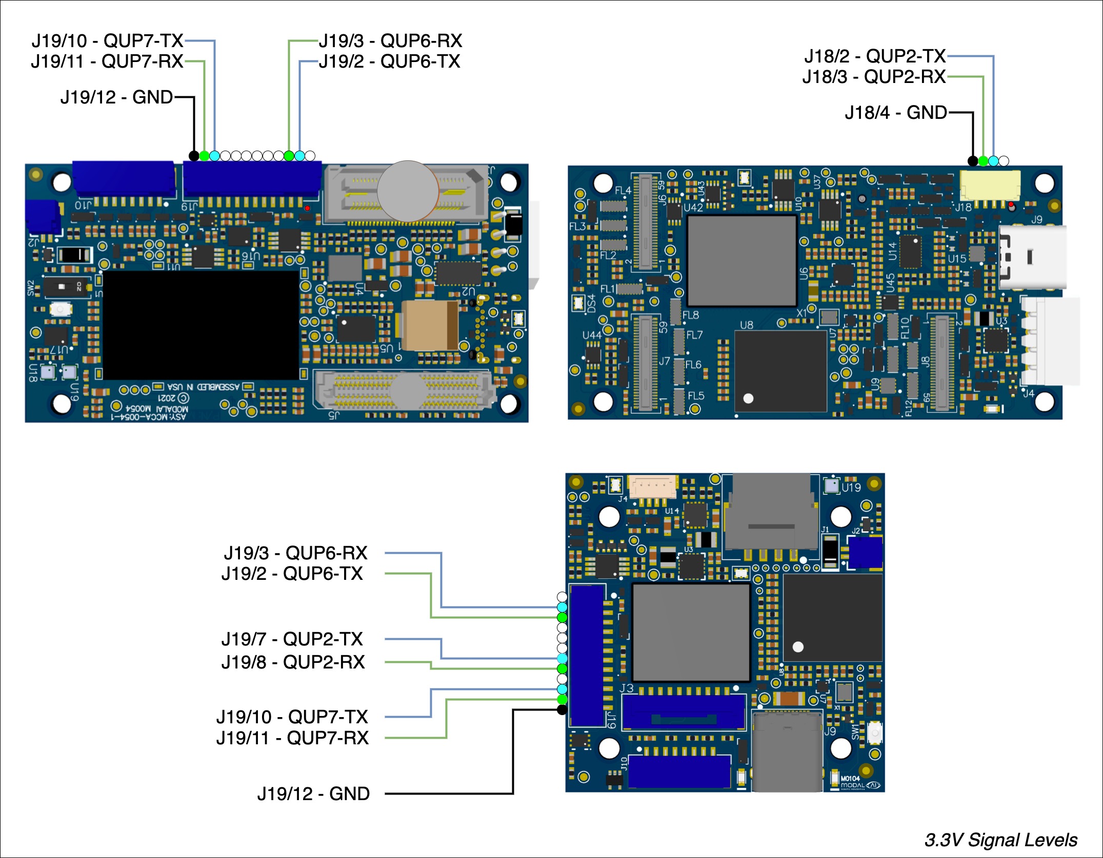
QUP2 - ESC UART
| Device | QUP2 |
| Pins | J18 Pins 2/3 (Tx/Rx) |
| Voltage | 3.3V, via directional level shifters |
| Code Sample | PX4 ESC Driver |
| Add-Ons | VOXL ESC |
QUP6 - GNSS UART
| Device | QUP6 |
| Pins | J19 Pins 2/3 (Tx/Rx) |
| Voltage | 3.3V, via directional level shifters |
| Code Sample | PX4 GPS |
| Add-Ons | VOXL 2 GPS Mag Assembly |
QUP7 - RCIO UART
| Device | QUP7 |
| Pins | J19 Pins 10/11 (Tx/Rx) |
| Voltage | 3.3V, via directional level shifters |
| Code Sample | PX4 px4io Driver |
| PX4 RC Driver | |
| Add-Ons | VOXL 2 IO |
| VOXL 2 GPS Mag Assembly |
SPI
The following is accurate as of System Image 1.3.
Overview
- Note: not shown is spidev11 on HS B2B J5
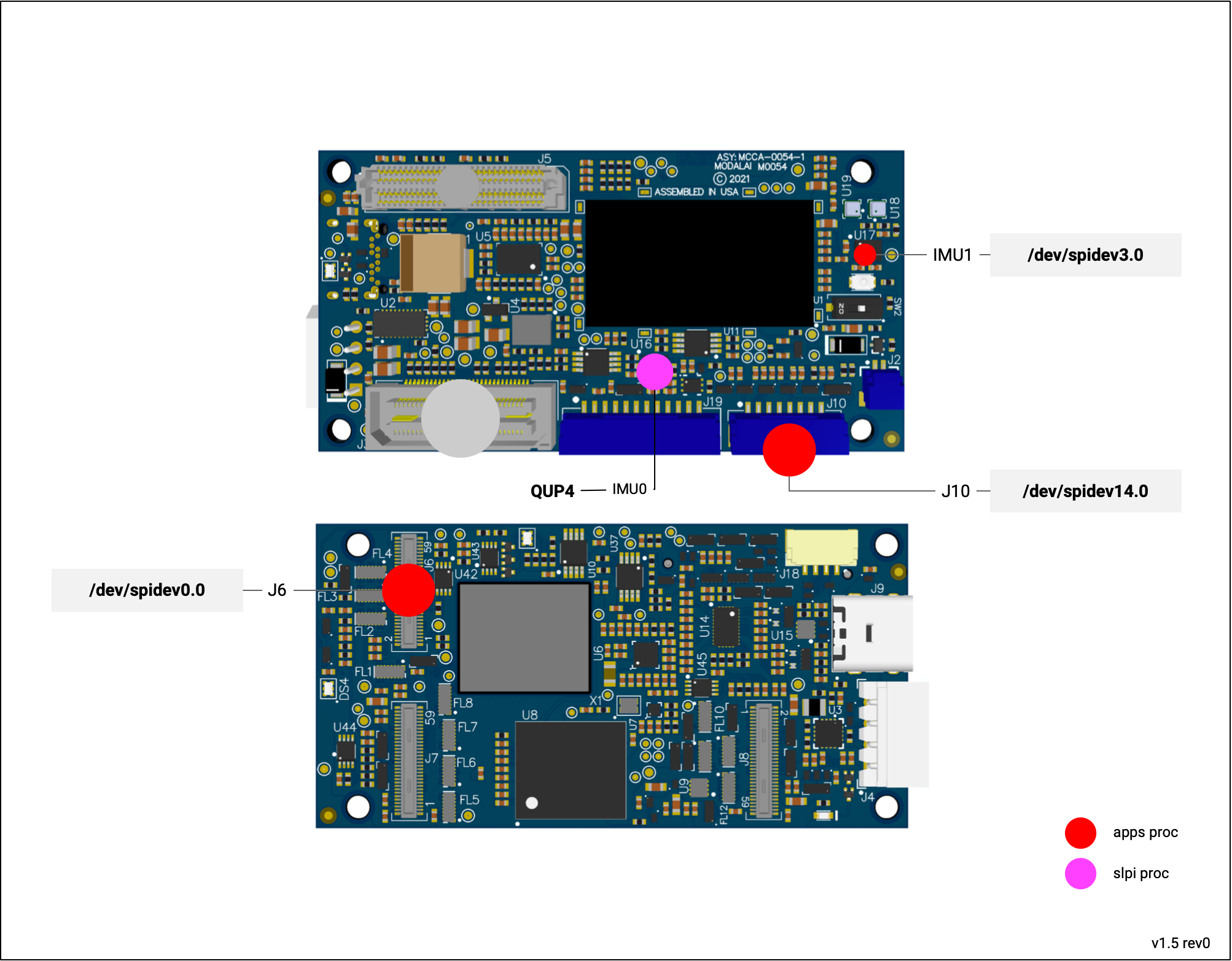
/dev/spidev0.0  --> camera group 0 (J6)
/dev/spidev3.0  --> internal IMU (TDK ICM-42688p)
/dev/spidev11.0 --> HS B2B connector (J5)
/dev/spidev14.0 --> external SPI (J10)
Apps Proc
SPI0 - Camera Group 0 SPI
| Device | /dev/spidev0.0 |
| Code Sample | VOXL SDK IMU Server |
| Voltage | 1.8V, directly connected to QRB5165, likely need to level shift |
| Pins | J6 - 34 MISO |
| J6 - 36 MOSI | |
| J6 - 38 SCLK | |
| J6 - 40 CS_N |
SPI3 - IMU1
| Device | /dev/spidev3.0, exposed in MPA as /run/mpa/imu_apps |
| Code Sample | VOXL SDK IMU Server |
| Voltage | Internal |
| Pins | U17 - 1 MISO |
| U17 - 14 MOSI | |
| U17 - 13 SCLK | |
| U17 - 12 CS_N |
SPI11 - J5 B2B SPI
Available in system image 1.5+
| Device | /dev/spidev11.0 |
| Code Sample | VOXL SDK IMU Server |
| Voltage | 3.3VDC |
| Pins | J5 - 53 MISO |
| J5 - 54 MOSI | |
| J5 - 55 SCLK | |
| J5 - 56 CS_N |
Available from M0130 addon - J8 pin 2-5
SPI14 - J10 External SPI
| Device | /dev/spidev14.0 |
| Code Sample | VOXL SDK IMU Server |
| Voltage | 3.3VDC |
| Pins | J10 - 2 MISO |
| J10 - 3 MOSI | |
| J10 - 4 SCLK | |
| J10 - 5 CS_N |
Available from J10 pins 2-5
SLPI Proc
QUP5 - IMU0
| Device | exposed via MAP at /run/mpa/imu_px4 |
| Code Sample | VOXL SDK IMU Server |
| Voltage | Internal |
| Pins | U16 - 1 MISO |
| U16 - 14 MOSI | |
| U16 - 13 SCLK | |
| U16 - 12 CS_N |
I2Cs
The following is accurate as of System Image 1.3.
Overview
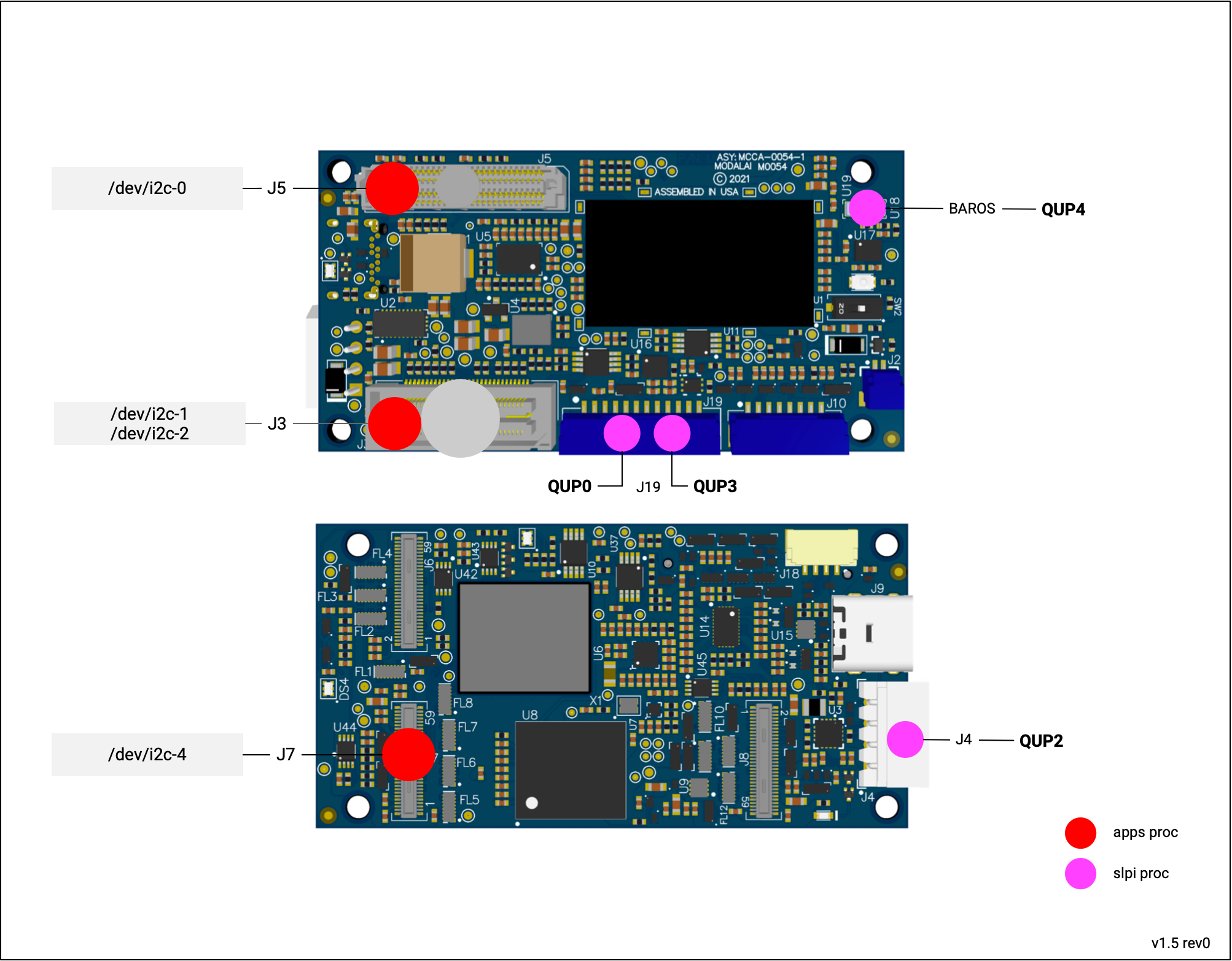
Apps Proc
i2c-0 - I2C2 - HS B2B I2C
/dev/i2c-0 is exposed on the HS B2B connector (J5) pins 8/9.
| Device | /dev/i2c-0 (new as of system image 1.5) |
| Code Sample | |
| Voltage | 3.3VDC |
| Pins | J5 Pin 8/9 (SDA/SCL) (GPIO 115/116) |
| Add-Ons | M0130 J8 Pins 8/9 (SDA/SCL) |
i2c-1 - I2C9 - B2B I2C - GPIO 125-126
/dev/i2c-1
| Device | /dev/i2c-1 (as of system image 1.5, was i2c-0 before) |
| Code Sample | |
| Voltage | 3.3VDC |
| Pins | J3 Pin 13/15 (SCL/SDA) (GPIO 126/125) |
i2c-2 - I2C10 - B2B I2C - GPIO 129-130
/dev/i2c-2 is exposed on the Legacy B2B connector’s pins 23 and 25, and available on add-on boards via a JST connector.
| Device | /dev/i2c-2 (as of system image 1.5, was i2c-1 before) |
| Code Sample | |
| Voltage | 3.3VDC |
| Connector | M0054 J3 Pins 23/25 (SCL/SDA) (GPIO 130/129) |
| Add-Ons | M0062 J9 Pins 4/5 (SDA/SCL) |
| M0090 J9 Pins 4/5 (SDA/SCL) |
i2c-3 - I2C15 - USB Redriver (internal, don’t use)
Status: dmesg shows some errors, need to investigate
| Device | /dev/i2c-3 (as of system image 1.5, was i2c-2 before) |
| Hardware | PN NB7VPQ904MMUTWG datasheet |
| Address: 0x1C |
i2c-4 - I2C1 - Camera Group 1 I2C
/dev/i2c-4 is exposed on the J7 camera group connector
| Device | /dev/i2c-4 |
| Code Sample | |
| Voltage | 1.8VDC |
| Connector | M0054 J7 Pins 34/36 (SCL/SDA) (GPIO 4/5) |
i2c-5 - I2C4 - HS B2B I2C
system image 1.7.2+
/dev/i2c-5 is exposed on the high speed board to board connector J5.
| Device | /dev/i2c-5 |
| Code Sample | |
| Voltage | 1.8VDC |
| Connector | M0054 J5 Pins 98/99 (SDA/SCL) (GPIO 8/9) |
i2cdetect Usage
For example, detecting devices on /dev/i2c-0
i2cdetect -r -y 0

     0  1  2  3  4  5  6  7  8  9  a  b  c  d  e  f
00:          -- -- -- -- -- -- -- -- -- -- -- -- --
10: -- -- -- -- -- -- -- -- -- -- -- -- -- -- -- --
20: -- -- -- -- -- -- -- -- -- -- -- -- -- -- -- --
30: -- -- -- -- -- -- -- -- -- -- -- -- 3c -- -- --
40: -- -- -- -- -- -- -- -- -- -- -- -- -- -- -- --
50: -- -- -- -- -- -- -- -- -- -- -- -- -- -- -- --
60: -- -- -- -- -- -- -- -- -- -- -- -- -- -- -- --
70: -- -- -- -- -- -- -- --
SLPI Proc
QUP0 - External Sensor (Magnetometer)
Typically used for magnetometer I2C connection.
| ID | QUP0 |
| Code Sample | |
| Voltage | 3.3VDC |
| Pins | J19 Pins 4/5 (SCL/SDA) |
| Add-Ons | VOXL 2 GPS Mag Assembly |
QUP2 - External Sensor (Power Monitoring)
Typically used for battery power monitoring I2C connection.
| ID | QUP2 |
| Code Sample | |
| Voltage | 5.0VDC |
| Pins | J4 Pins 3/4 (SCL/SDA) |
| Add-Ons | VOXL PMv3 |
QUP3
Future use.
| ID | QUP3 |
| Code Sample | |
| Voltage | 3.3VDC |
| Pins | J19 Pins 7/8 (SCL/SDA) |
| Add-Ons | NA |
QUP4 - Internal Sensors (Barometers)
Connected to onboard barometers.
| ID | QUP4 |
| Code Sample | |
| Hardware | TDK-ICP10100 @ 0x63h |
| bmp388 @ 0x76h |
GPIOs
Apps Proc
Example code: voxl-gpio.c
voxl-gpio-mod Kernel Driver
To help with GPIO initialization and exporting to user space, see meta-voxl2/recipes-kernel/voxl-gpio-mod
Starting SDK 1.2.X/System Image 1.7.3, GPIOs are exported by default in /sys/class/gpio, the GPIO have an offest of 1100 (e.g. GPIO 84 = 1184).
J3 - B2B
See changelog for version info.
| GPIO | Direction | Description |
|---|---|---|
| 52 | In | J3 Pin 7, pulldown - exposed by M0090, M0062 - J8 pin 2 at 3P3V |
| 53 | Out | J3 Pin 9, default high, 1P8V - exposed by M0090, M0062 - J8 pin 3 at 3P3V (for M0048 pDDL_EN_N) |
| 54 | Out | J3 Pin 19, default low, 1P8V - exposed by M0090, M0062 - J8 pin 4 at 3P3V |
| 55 | Out | J3 Pin 17, default low, 1P8V - exposed by M0090, M0062 - J8 pin 5 at 3P3V |
| 131 | Out | J3 Pin 38 - default low, 1P8V |
| 124 | Out | J3 Pin 40 - default high,1P8V |
J5 - HS B2B
See changelog for version info.
| GPIO | Direction | Description |
|---|---|---|
| 0 | In/Out | J5 Pin 46, default high, 1P8V |
| 1 | In/Out | J5 Pin 47, default high, 1P8V |
| 36 | In/Out | J5 Pin 97, default high, 1P8V (system image 1.7.3+) |
| 37 | In/Out | J5 Pin 98, default high, 1P8V (system image 1.7.3+) |
| 56 | In/Out | J5 Pin 50, default high, 1P8V |
| 57 | In/Out | J5 Pin 51, default high, 1P8V |
| 85 | In/Out | J5 Pin 82, default high, 1P8V |
| 86 | In/Out | J5 Pin 81, default high, 1P8V |
| 87 | In/Out | J5 Pin 80, default high, 1P8V |
| 88 | In/Out | J5 Pin 78, default high, 1P8V |
| 89 | In/Out | J5 Pin 79, default high, 1P8V - for M0130, controls whether interface on J8 is SPI (default) or UART (DT change needed to convert) |
| 152 | In/Out | J5 Pin 44, default high, 1P8V |
| 153 | In/Out | J5 Pin 43, default low, 1P8V |
| 154 | In/Out | J5 Pin 42, default low, 1P8V |
| 155 | In/Out | J5 Pin 41, default low, 1P8V |
J6
Note:
- As of system image 1.5
- If using
var00.1kernel, these are not available for use as they’re used in reset signaling
| GPIO | Direction | Description |
|---|---|---|
| 113 | In/Out | J6 - 16, exposed though interposer M0076 TP2, Warning: used in camera HW reset signaling |
| 110 | In/Out | J6 - 18, exposed though interposer M0076 TP3. Warning: used in camera HW reset signaling |
J7
As of system image 1.5:
| GPIO | Direction | Description |
|---|---|---|
| 6 | In/Out | J7 - 38, exposed though interposer M0076 TP7 |
| 7 | In/Out | J7 - 40, exposed though interposer M0076 TP8 |
J8
As of system image 1.5:
| GPIO | Direction | Description |
|---|---|---|
| 12 | In/Out | J8 - 34, exposed though interposer M0076 TP5 |
| 13 | In/Out | J8 - 36, exposed though interposer M0076 TP6 |
J10
| GPIO | Direction | Description |
|---|---|---|
| 46 | Out | J10 Pin 6 (SPI4 CS1, used for Spektrum bind) |
LEDs
| GPIO | Direction | Description |
|---|---|---|
| 82 | Out | DS2 LED, Red |
| 83 | Out | DS2 LED, Green |
| 84 | Out | DS2 LED, Blue |
Regulators
| GPIO | Direction | Description |
|---|---|---|
| 157 | Out | Controls U41, the 5V/2A switchable power supply for USB |
| 159 | Out | Controls U24, the 3.3VDC supply for RC / VOXL2 IO, J19 pin 9 |
HW ID
As of system image 1.7.3:
| GPIO | Direction | Description |
|---|---|---|
| 48 | In | SOM detect, id_som_1 |
| 49 | In | SOM detect, id_som_2 |
| 50 | In | SOM detect, id_mai_4 |
| 51 | In | SOM detect, id_mai_4 |
| Machine | 48 | 49 | 50 | 51 |
|---|---|---|---|---|
| M0054 | X | X | 0 | 0 |
| M0104 | X | X | 1 | 1 |
| M0154 | 1 | 0 | 1 | 0 |
UART/SPI select (VOXL2 Mini)
As of system image 1.7.3:
On VOXL 2 Mini, J10 can expose a UART or SPI based on this GPIO (default UART). Not kernel rebuild required to change from UART to SPI.
| GPIO | Direction | Description |
|---|---|---|
| 67 | Out | J10 level shift control, default low (selects UART) |
Camera Sync Util GPIOs
As of system image 1.7.7:
See meta-voxl2/recipes-kernel/voxl-fsync-mod
| GPIO | Direction | Description |
|---|---|---|
| 109 | Out | Default low |
Camera Use
| GPIO | Direction | Description |
|---|---|---|
| 110 | In | Will be used by M0173 config, camera ID 6 reset |
| 111 | In | Used by stereo sync with ov7251/ov9782, J8 pin 18, D0006 config |
| 112 | In | Used by future camera config |
| 113 | In | Used by stereo sync with ov7251/ov9782, J6 pin 18, D0006 config |
| 114 | In | used by fugure camera config |
PCIe
PCIe2
Starting system image 1.7, we’ve disabled the PCIe interface in favor of exposing GPIOs.
Serial Debug Console
This is enabled in DEBUG builds of the system image and not enabled by default.
You can access via:
- M0017
APQ Console.
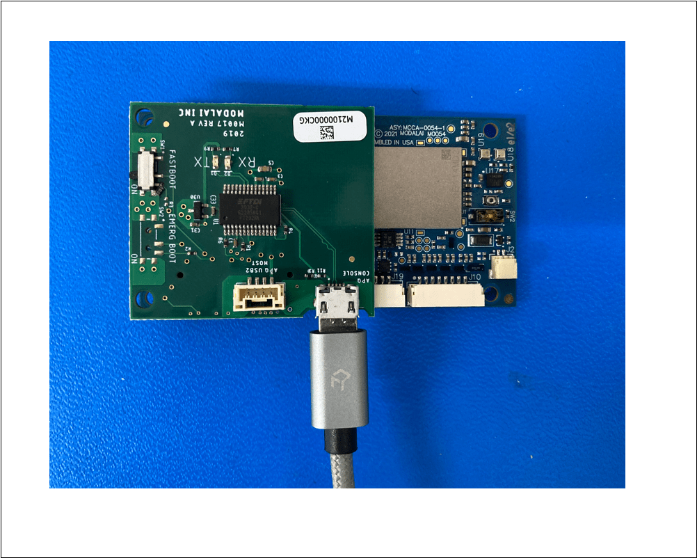
- M0062 J6.
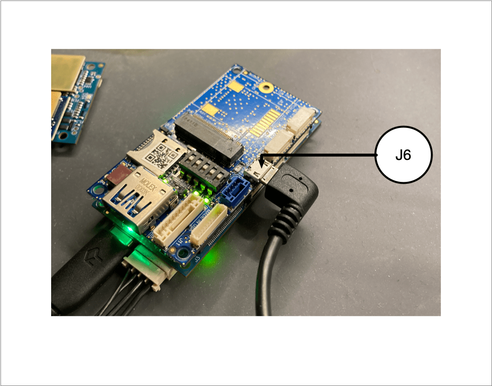
Running the following after power on, for example:
screen /dev/tty.usbserial-AU03BMG9 115200
Watch the booting progress:
[  OK  ] Stopped Modem Init Service.
[  OK  ] Started Modem Init Service.
[  OK  ] Stopped Modem Init Service.
[FAILED] Failed to start Modem Init Service.
See 'systemctl status init_sys_mss.service' for details.
[  OK  ] Started depends update.

Ubuntu 18.04.5 LTS qrb5165-rb5 ttyMSM0

qrb5165-rb5 login:
Kernel Modules
voxl-fsync-mod
Used to generate image sensor sync pulses.
voxl-gpio-mod
Used to export GPIO to user space.
voxl-platform-mod
Used to export machine specific to user space for operational ease.