Power Module v2 Datasheet
Table of contents
Specification
Inputs
For benchtop development, the VOXL-ACC-PS or PS-XT60 wall power supplies can be used.
- J2: 5V DC Barrel Jack Input
- Switchcraft Inc. RAPC712X, 5A contacts
- TP3 (+) TP1 (-) XT60 LIPO battery input cable via manual solder pads (XT60 can be changed to anything with a cable)
- LIPO range 2S-5S [2 cell (6.4V min, 7.4V nom, 8.4V max) 5 cell ( 16V min, 18.5V nom, 21V max)]
- Note: Absolute max voltage of design is limited to 25V due to capacitor ratings. A 27V zener is present which would clamp anything higher than 27V.
- LIPO range 2S-5S [2 cell (6.4V min, 7.4V nom, 8.4V max) 5 cell ( 16V min, 18.5V nom, 21V max)]
Outputs
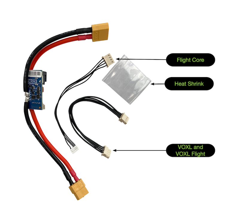
- J1: Molex 4-position 22-05-7045 2.5mm R/A male connector, 3A DC per pin @22 AWG (PCB/wire gauge dependent)
- Mates with VOXL and VOXL Flight power input connectors via
MCBL-00001or Flight Core viaMCBL-00003- Pin 1: 5V DC OUT
- Pin 2: DGND
- Pin 3: I2C SCL (5V levels)
- Pin 4: I2C SDA (5V levels)
- Mates with VOXL and VOXL Flight power input connectors via
I/O
- I2C bus @ 5V SCL/SDA on output connector for reading LIPO and 5VDC Voltage and Current metrics with Qty-2 LTC2946
- LIPO on I2C ADDR 0xD4, Device U1
- 5V Output on I2C ADDR 0xD6, Device U2
Sensing
A PX4 driver is already integrated starting with PX4 v1.10 and can be viewed here.
The maximum amperage that can be read by the driver before saturating the ADC is 90A, although the XT60 connector limits the system useability to 60A.
One can tweak the Rsense values if needed here
Operating Range/Environmental
- Selected to match the hardware designs at the time of 0C to 55C
- Not designed for dust or moisture ingress protection or solar load protection
AKA
- May be found referenced as
APMorM0009
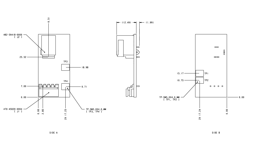
2D/3D Drawings
Note: These 3D files contain all components on them. Some board configurations do not install “DNI” certain connectors or components. Please refer to the included diagrams and design schematics for more detailed information
Physical Dimensions
20mm x 40mm