
FLIR Hadron 640R Support on VOXL 2 and VOXL 2 Mini
Table of contents
Overview
VOXL 2 and VOXL 2 Mini support the FLIR Hadron 640R dual thermal/EO payload. A ModalAI adapter set and micro-coax cables are required.
Required Hardware
- FLIR Hadron 640R (not included)
- M0202 (or M0159) + M0181 adapters
- MCBL-00084-180 micro coax 180mm cables, qty 2 (shorter options available)
M0202 is a newer version of M0159 with identical functionality and a slightly better fit into the Hadron. References to M0159 below apply equally to M0202.
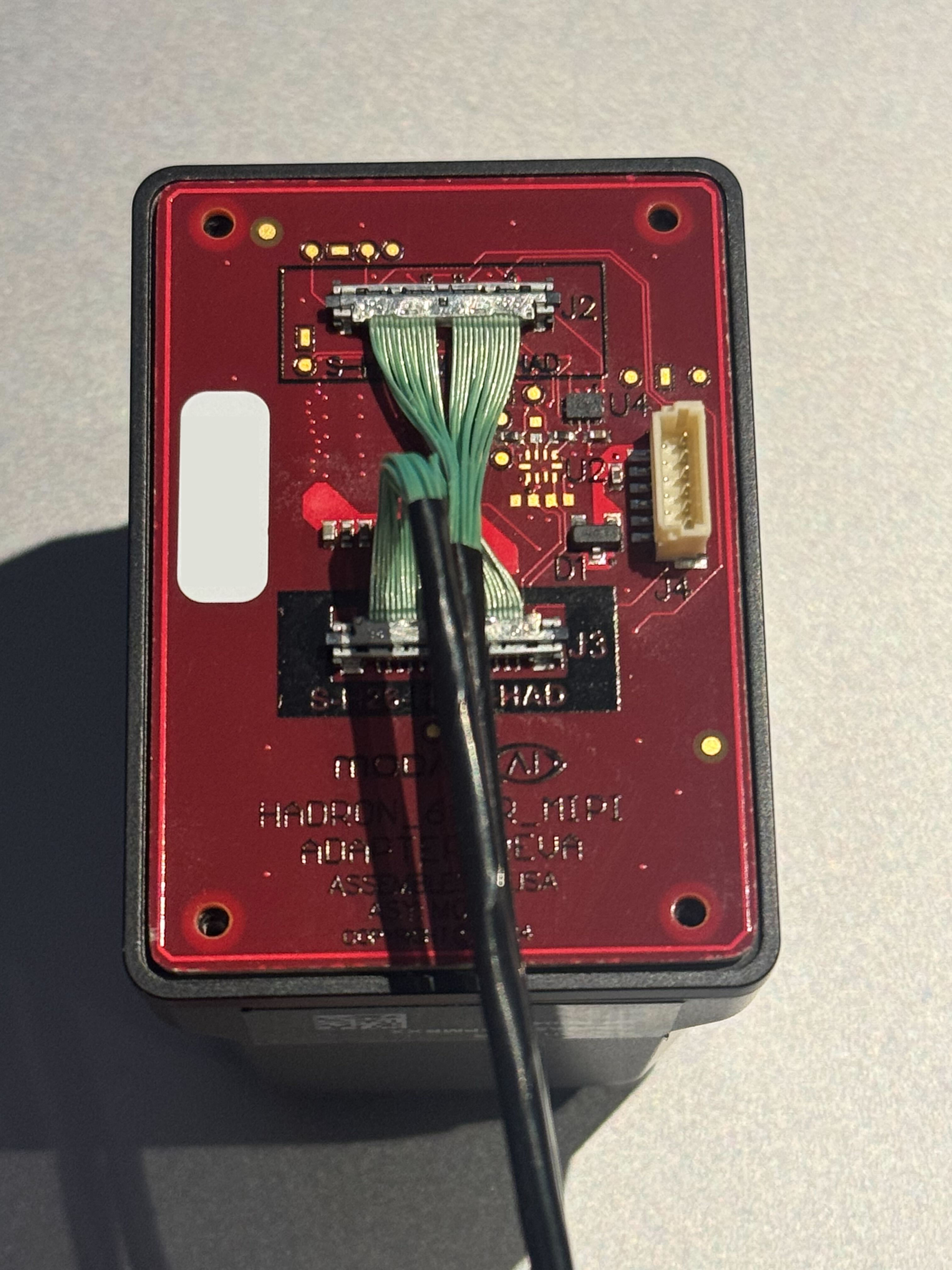
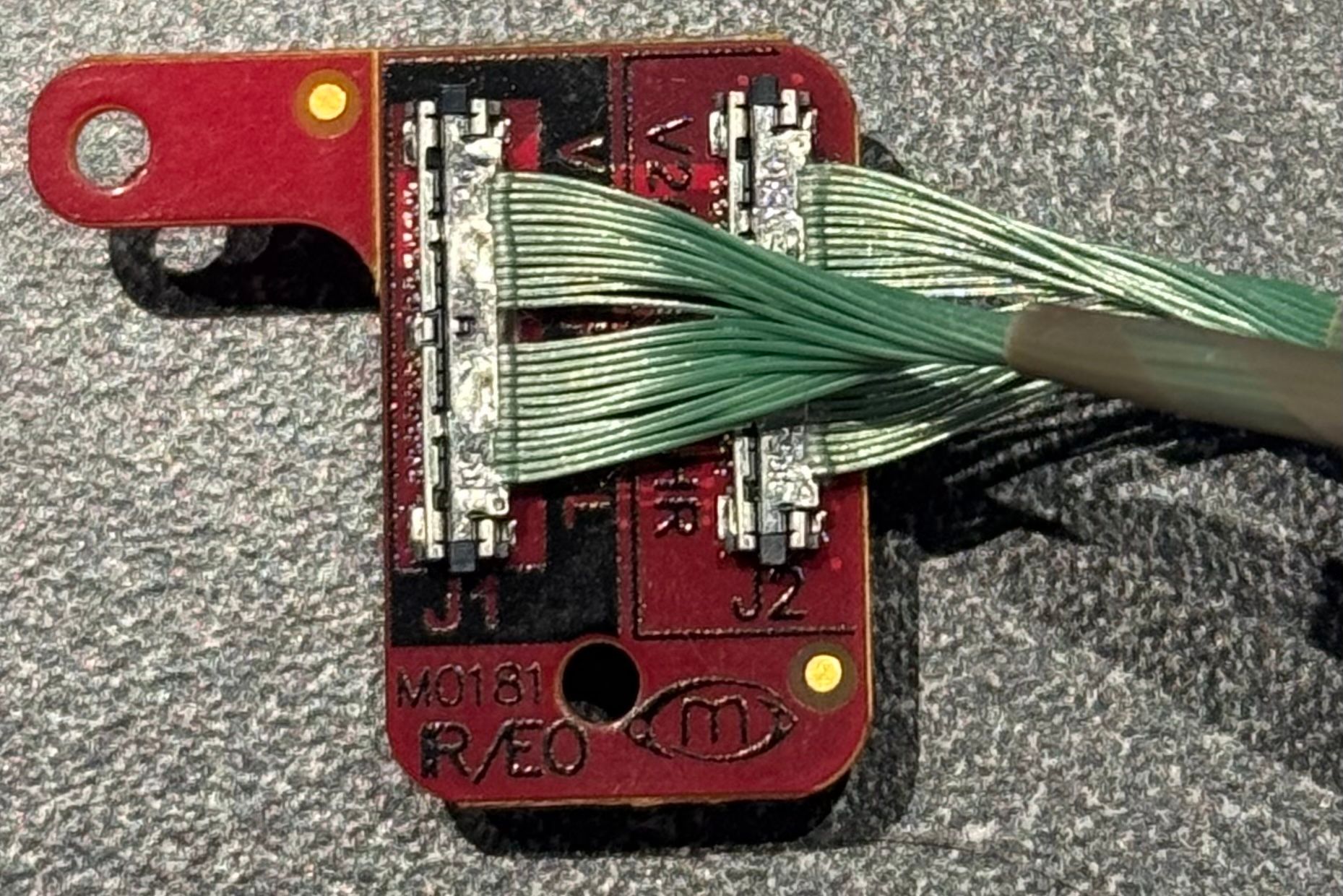
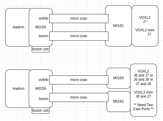
Mate M0159 to M0181 with care. The two coax cables are identical, but their order cannot be swapped: M0159 J2 (5L) connects to M0181 J1 (5L), and M0159 J3 (HR) connects to M0181 J2 (HR) — HR to HR, 5L to 5L, as labeled next to the connectors on both boards. Connecting them incorrectly will likely damage the Hadron 640R due to incompatible power rails. Shipped assemblies come correctly connected and tested.
Interfacing Options
- With the M0159 adapter plugged into the back of the Hadron 640R, the USB port on M0159 can power the Hadron and configure the IR sensor over USB.
- To use the MIPI connection for the IR sensor, the sensor must be configured to enable MIPI output — see the M0153 software instructions.
- On some Hadron firmware versions, switching from 60 to 30 FPS is required (as described in that document) because 60 FPS frame timing can be incompatible with the VOXL 2 camera ISP, stopping the stream shortly after start.
- Hadron firmware
3.0.26416has been tested to work at 60 FPS. On other firmware, select 30 FPS using the frame-skip feature in the Hadron configuration.
- It is safe to have the Hadron connected to both VOXL 2 and USB — just make all connections while VOXL 2 is powered off.
- The USB connection also works with the FLIR GUI for configuring the IR sensor, and with the standard Linux UVC driver for viewing IR images.
Hardware Setup
Connect the M0159 Adapter to the Hadron
- If necessary, remove any interface boards plugged into the Hadron 640R so the M0159 sits flush against its back.
- Make sure the M0159 connector aligns with the Hadron.
- See the images below for a correctly mated connection.
Connect M0181 to VOXL 2 or VOXL 2 Mini
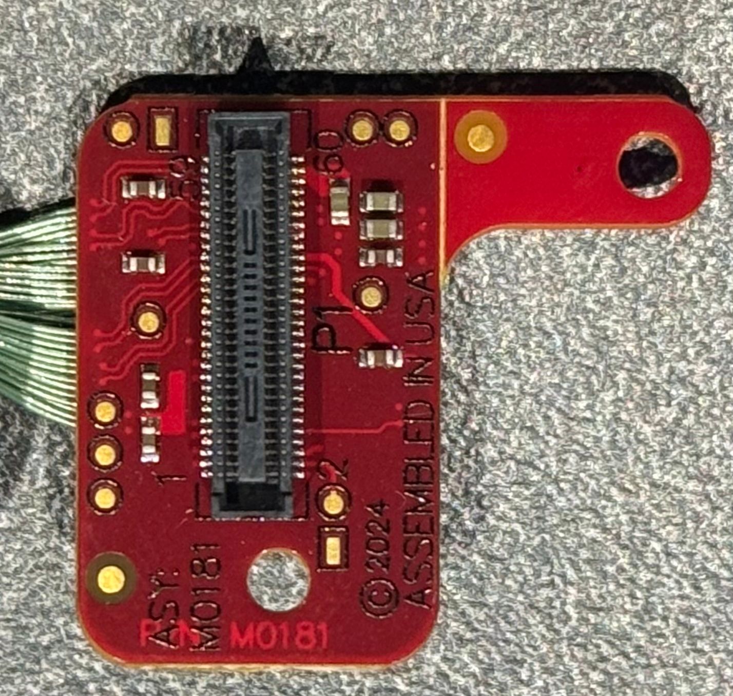
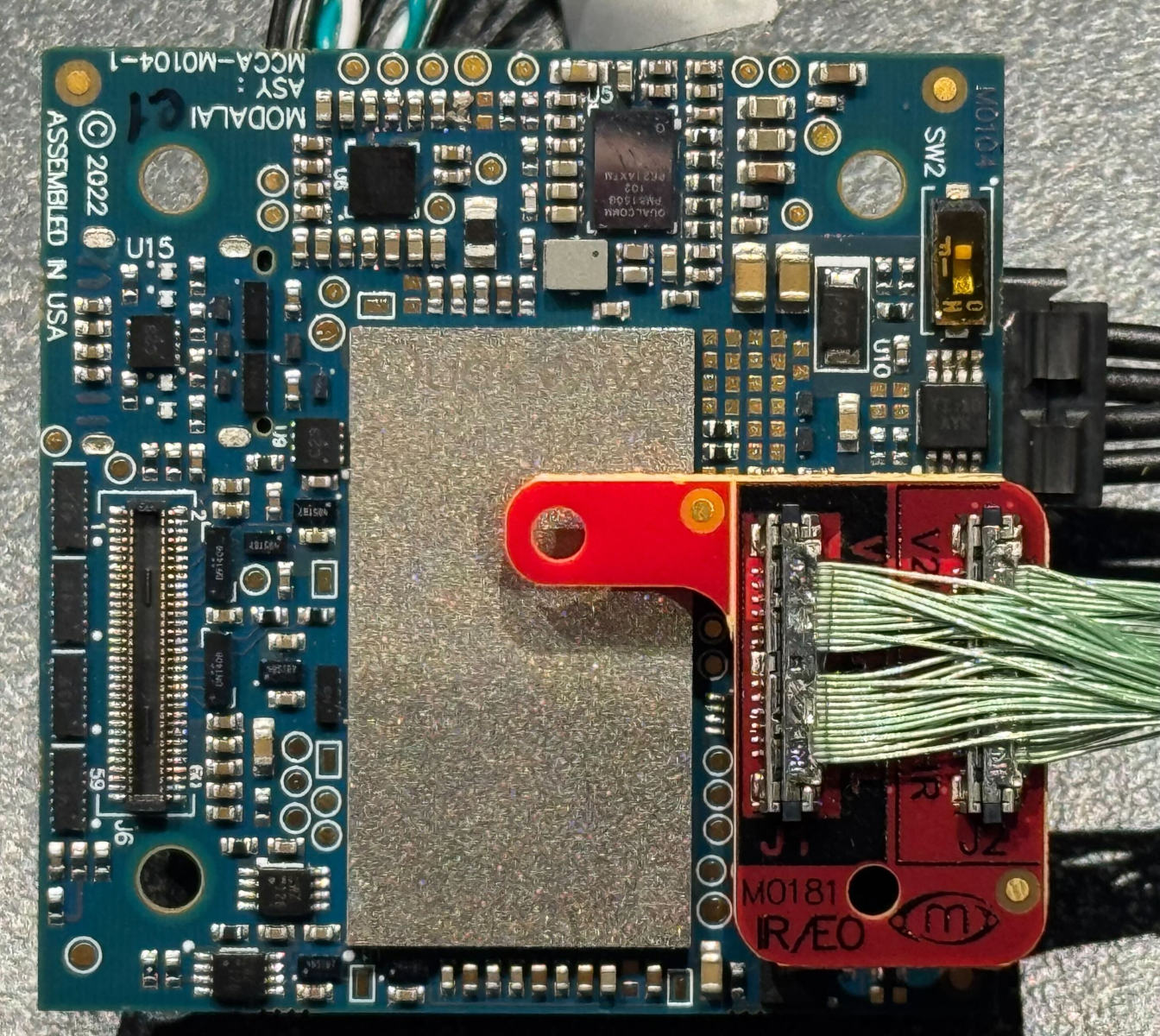
- Check pin alignment on the connectors: the mounting holes should align, and the M0181 tab will hover above the main SoC (the tab can be removed if not needed).
- VOXL 2 Mini supports the Hadron on J6 or J7 with the default kernel:
- J6 — sensormodules
com.qti.sensormodule.boson_0.binandcom.qti.sensormodule.ov64b40_1.bin - J7 — sensormodules
com.qti.sensormodule.boson_2.binandcom.qti.sensormodule.ov64b40_3.bin
- J6 — sensormodules
- VOXL 2 supports the Hadron on J7 or J8:
- J7 — sensormodules
com.qti.sensormodule.boson_2.binandcom.qti.sensormodule.ov64b40_3.bin— must use kernel variant 0 - J8 — sensormodules
com.qti.sensormodule.boson_4.binandcom.qti.sensormodule.ov64b40_5.bin— must use kernel variant 1 (for M0173) - J6 is possible but requires a kernel change and is not recommended.
- J7 — sensormodules
Software Setup
Install VOXL SDK 1.4.0 or later on the VOXL 2 or VOXL 2 Mini.
Confirm the Sensormodule Drivers Exist
All camera drivers ship in the chi-cdk directory (present but unused until copied):
ls /usr/share/modalai/chi-cdk/ov64b40   # com.qti.sensormodule.ov64b40_0.bin ... 5.bin
ls /usr/share/modalai/chi-cdk/boson     # com.qti.sensormodule.boson_0.bin ... 5.bin
Copy the Correct Sensormodule Drivers
Select the sensormodule index matching the camera connector the Hadron is on (this example is VOXL 2 J7):
cp /usr/share/modalai/chi-cdk/boson/com.qti.sensormodule.boson_2.bin /usr/lib/camera/
cp /usr/share/modalai/chi-cdk/ov64b40/com.qti.sensormodule.ov64b40_3.bin /usr/lib/camera/
Also confirm the sensor libraries exist:
/usr/lib/camera/com.qti.sensor.ov64b40.so
/usr/lib/camera/com.qti.sensor.boson.so
Configure the CCI Mux on M0159 via GPIO
The Hadron module has a single CCI bus, while the two VOXL 2 camera ports in use (IR + RGB) expect two CCI buses. A mux on M0159 bridges them:
- For the J7 option, drive GPIO 6 high to connect J7U CCI to the Hadron’s camera CCI (for J6/J8 see below).
- This must be done after every reboot, before starting the camera server.
- After enabling the mux, the CCI buses for J7L and J7U are physically connected. Camera probing happens sequentially at camera-server startup, and VOXL 2 does not normally talk to the IR sensor after streaming starts, so bridging the buses is not a problem.
# VOXL 2 / VOXL 2 Mini J6
voxl-gpio -m 30 out && voxl-gpio -w 30 1

# VOXL 2 / VOXL 2 Mini J7
voxl-gpio -m 6 out && voxl-gpio -w 6 1
VOXL 2 J8: the mux-enable pin for J8 is GPIO 14, but that pin is mapped to UART5_TX (
/dev/ttyHS0) and cannot be driven as GPIO (see the J8 pinout). When the UART is idle its TX line rests high, which happens to enable the mux — so there is nothing to configure; just do not use/dev/ttyHS0while the Hadron is on J8.
Testing
Detect Cameras
voxl2-mini:/$ voxl-camera-server -l
DEBUG:   Attempting to open the hal module
DEBUG:   SUCCESS: Camera module opened on attempt 0
DEBUG:   ----------- Number of cameras: 2

DEBUG:   Cam idx: 0, Cam slot: 2, Slave Address: 0x00D4, Sensor Id: 0x00FF
DEBUG:   Cam idx: 1, Cam slot: 3, Slave Address: 0x006C, Sensor Id: 0x6442
DEBUG:   Note: This list comes from the HAL module and may not be indicative
DEBUG:      of configurations that have full pipelines

DEBUG:   Number of cameras: 2
...
Minimum Configuration
Paste into /etc/modalai/voxl-camera-server.conf:
{
    "version":  0.1,
    "fsync_en": false,
    "fsync_gpio":   109,
    "cameras":  [
        {
            "type":             "boson",
            "name":             "boson",
            "enabled":          true,
            "camera_id":        0,
            "fps":              30,
            "en_preview":       true,
            "en_misp":          false,
            "preview_width":    640,
            "preview_height":   512,
            "en_raw_preview":   true,
            "en_small_video":   false,
            "en_large_video":   false,
            "ae_mode":          "off"
        },
        {
            "type":             "ov64b",
            "name":             "hires",
            "enabled":          true,
            "camera_id":        1,
            "fps":              30,
            "en_preview":       true,
            "en_misp":          false,
            "preview_width":    1920,
            "preview_height":   1080,
            "en_raw_preview":   false,
            "en_small_video":   false,
            "en_large_video":   false,
            "en_snapshot":      false,
            "ae_mode":          "isp",
            "gain_min":         100,
            "gain_max":         32000
        }
        ]
}
Start the Camera Server
Run voxl-camera-server in the foreground first to confirm everything works, and view the streams in voxl-portal. Without voxl-portal, streams can be checked with voxl-inspect-cam:
voxl2-mini:/$ voxl-list-pipes
boson
hires_color
hires_grey

voxl2-mini:/$ voxl-inspect-cam boson hires_color
|   Pipe Name |  bytes  | wide |  hgt |exp(ms)| gain | frame id |latency(ms)|  fps |  mbps  | format
|       boson |  327680 |  640 |  512 |  0.00 |  799 |      456 |     11.2  | 60.0 |  157.3 | RAW8
| hires_color | 3110400 | 1920 | 1080 | 16.64 |  324 |      224 |     40.0  | 29.8 |  741.8 | NV12
Very high resolution streams viewed as YUV (transferred as MJPG by voxl-portal) cost significant CPU to encode and a lot of bandwidth to stream.
Supported Resolutions and Modes
- The IR sensor supports
640x512resolution. - The OV64B currently supports the RAW modes below; the camera pipeline picks the best mode for the requested resolution and FPS.
- For example, requesting
3840x2160at 30 FPS actually selects4624x3472, because it matches the desired FPS. - The selected mode can be checked with
logcat | grep -i selectedbefore starting the camera server — the selected resolution is printed for each camera.
- For example, requesting
# (Mbps per CSI lane)
Mode0_9248x6944_10fps_2500.8Mbps
Mode1_4624x3472_30fps_PD_1136x860_1502Mbps
Mode4_3840x2160_60fps_2500.8Mbps
Mode5_1920x1080_240fps_2500.8Mbps
Mode6_1920x1080_30fps_800Mbps
Maximum Resolution
9248x6944 at 9 FPS, configured in voxl-camera-server.conf:
"preview_width":    9248,
"preview_height":   6944,
At this >8K resolution the Qualcomm ISP runs in dual-VFE mode, which means no other non-RAW camera can use the ISP. The MISP approach below does not use the Qualcomm ISP and avoids this limit.
MISP (ModalAI ISP)
MISP is ModalAI’s own image processing pipeline in voxl-camera-server. It bypasses the Qualcomm ISP entirely, so it is not subject to ISP resource limits like the dual-VFE constraint above — freeing the hardware ISP for other cameras. Electronic image stabilization (EIS) also runs on the MISP path.
MISP is enabled per camera in /etc/modalai/voxl-camera-server.conf:
"en_misp":      true,
"misp_width":   1920,
"misp_height":  1080,
MISP cameras publish their streams on *_misp_* pipes (e.g. hires_misp_color, hires_misp_encoded), and an onboard video encoder can be enabled with the misp_venc_* fields (codec, bitrate control — including an ROI mode that encodes the frame center at higher quality — and bitrate). See the voxl-camera-server page for the full configuration reference.
Images and Diagrams
M0159 Adapter Plugged into Hadron 640R
M0181 Adapter
M0181 top:
M0181 bottom:
M0181 Plugged into VOXL 2 Mini J7
Connection Diagram
The primary configuration is M0159 + M0181; M0159 + M0155 + M0162 is also possible.
USB Connector on M0159 (J4)
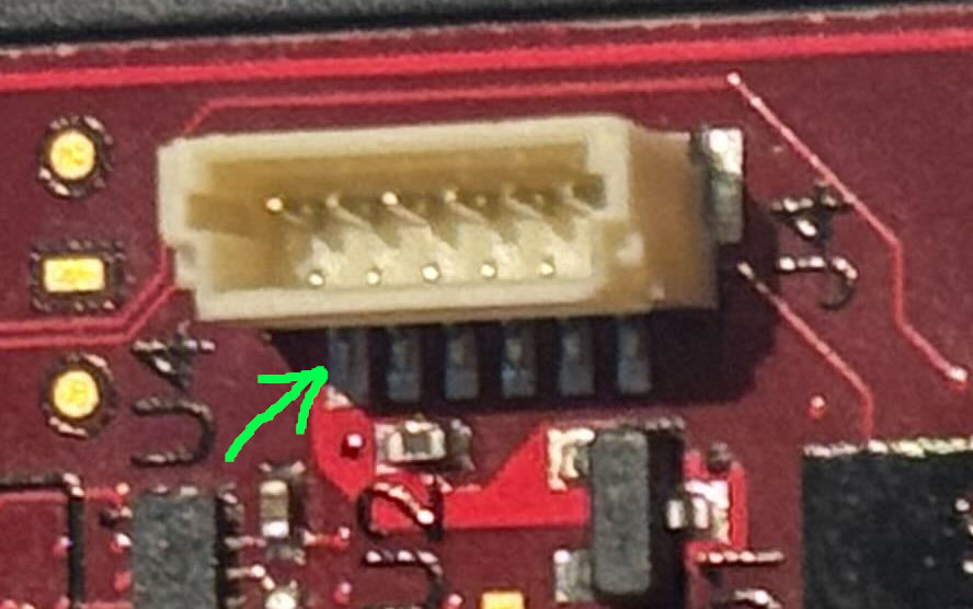
M0159 has a 6-pin USB connector (J4), connector type BM06B-SRSS-TBT. Pin 1 is marked with a dot on the silkscreen (arrow in the image below).
| Pin# | Signal | Notes/Usage |
|---|---|---|
| 1 | 5V_VDC | 5V power input from USB |
| 2 | GND | GND |
| 3 | SYNC_GPIO | Unused |
| 4 | GND | GND |
| 5 | USB_D_P | USB 2.0 Data P |
| 6 | USB_D_N | USB 2.0 Data N |