
ModalAI M0184 Gemini 915MHz ELRS
ModalAI's M0184 Gemini 915MHz ELRS
Table of contents
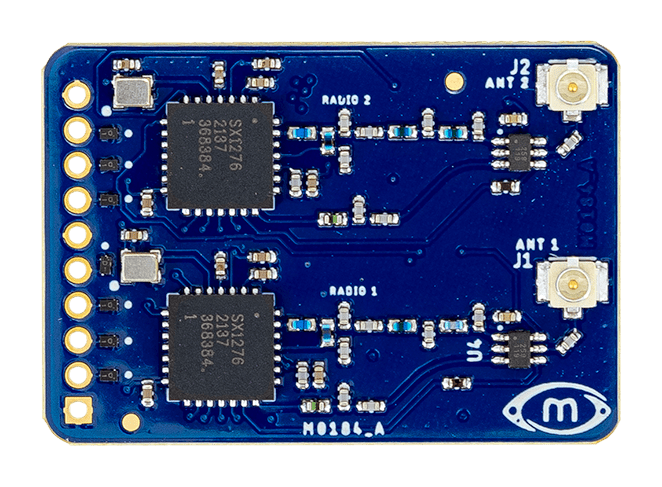
Summary
Transmitter Compatibility
In general, follow Express LRS guidance selecting 900MHz compatible transmitters.
The M0184 runs ELRS 3.x receiver firmware bundled with voxl-elrs. A transmitter must meet all of the following to bind:
- ELRS v3 firmware on the transmitter module. Receiver and transmitter must be on the same major ELRS version. ELRS 4.x transmitters are not supported with the M0184 and must be downgraded to the latest ELRS 3.x release using the standard ExpressLRS transmitter update process.
- A 900 MHz or dual-band module, operating in the low band.
- Not a 2.4 GHz-only module. 2.4 GHz-only transmitters, for example the internal ELRS module of the Radiomaster Boxer, cannot bind to the M0184.
The ELRS v3 requirement applies to the M0184. The M0220 transceiver is compatible with ELRS v4+ devices by default.
VOXL SDK Support
SDK 1.4.1 or newer required. For VOXL SDK usage, please see voxl-elrs.
Dimensions
3D Drawings
TODO
2D Drawings
TODO
Features
| Feature | Details |
|---|---|
| Weight | TODO g |
| HxW | 33mm x 22mm |
| Frequency Bands | 915MHz (default), configurable to 868MHz |
| Input Voltage | 5VDC, 350mA max (TX/RX) |
| Serial Output | CRSF, 420k default |
| RF Chip | Dual SX1276 |
| Antenna | IPEX MHF |
| Firmware | ELRS 3.5.3.x |
| MCU | 72MHz, 32-bit ARM M3 STM32F103C8T6 |
| Memory | 20Kb RAM |
| 64Kbit Flash | |
| Inputs | UART, push button |
| Outputs | QTY PWM, UART, R/G LED |
Hardware
Hardware Block Diagram
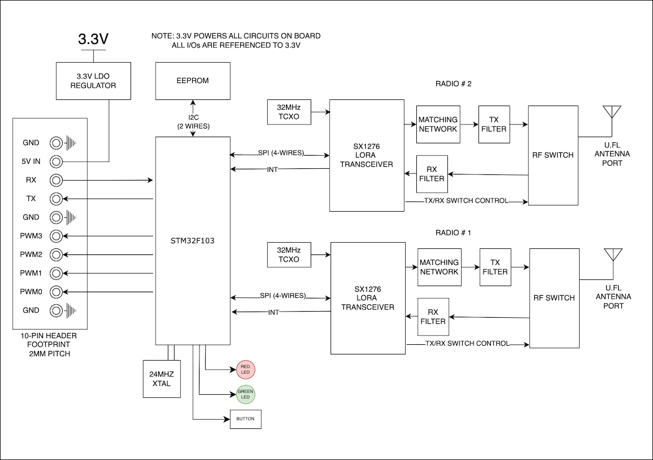
Connectors
Summary
BETA release: prototype hardware shown here
Hover a connector to identify it — click to jump to its details.

| Connector | Description |
|---|---|
| J1 | Antenna 1 |
| J2 | Antenna 2 |
| J4 | PWM, RC UART |
| S1 | Bind button |
| D1 | Green LED |
| D2 | Red LED |
J4 - Header Solder Pads
| Pin | Name | Notes |
|---|---|---|
| 1 | GND | |
| 2 | P0 | PWM Channel 0, 3P3V |
| 3 | P1 | PWM Channel 1, 3P3V |
| 4 | P2 | PWM Channel 2, 3P3V |
| 5 | P3 | PWM Channel 3, 3P3V |
| 6 | GND | |
| 7 | TX | ELRS TX (to VOXL2), 3P3V, 420k CRSF |
| 8 | RX | ELRS RX (from VOXL2), 3P3V, 420k CRSF |
| 9 | 5V | Input Power, 5P0V |
| 10 | GND |
J1 - ANT1
RF ANT1 path (915MHz).
J2 - ANT2
RF ANT2 path (915MHz).
S1 - Bind button
Used to put receiver in bind mode.
To enter binding mode, press and hold the Bind button while powering on.
D1 - Green LED
Solid when bound.
D2 - Red LED
Status LED, follows ELRS standards
A constant slow blink means the receiver is not connected to a transmitter. The LED turns solid once a link is established. On a vehicle, this is the red light that keeps blinking until the transmitter is powered on and connected.
Recommended Antennas
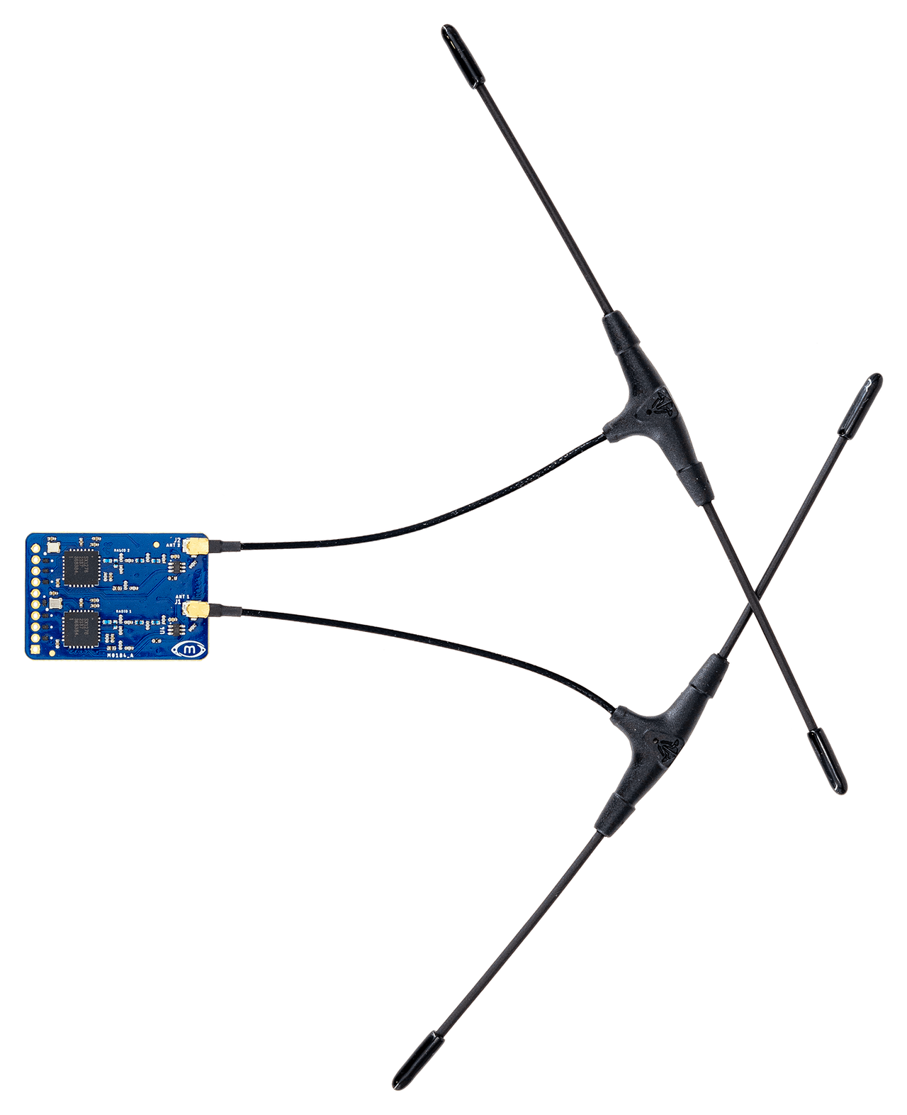
IPEX MHF + T antenna.
Programming Test Points
TODO
User Guides
VOXL SDK
For VOXL SDK usage, please see voxl-elrs.
Also see the M0184 Software User Guide.
VOXL 2 Wiring Guide (M0054)
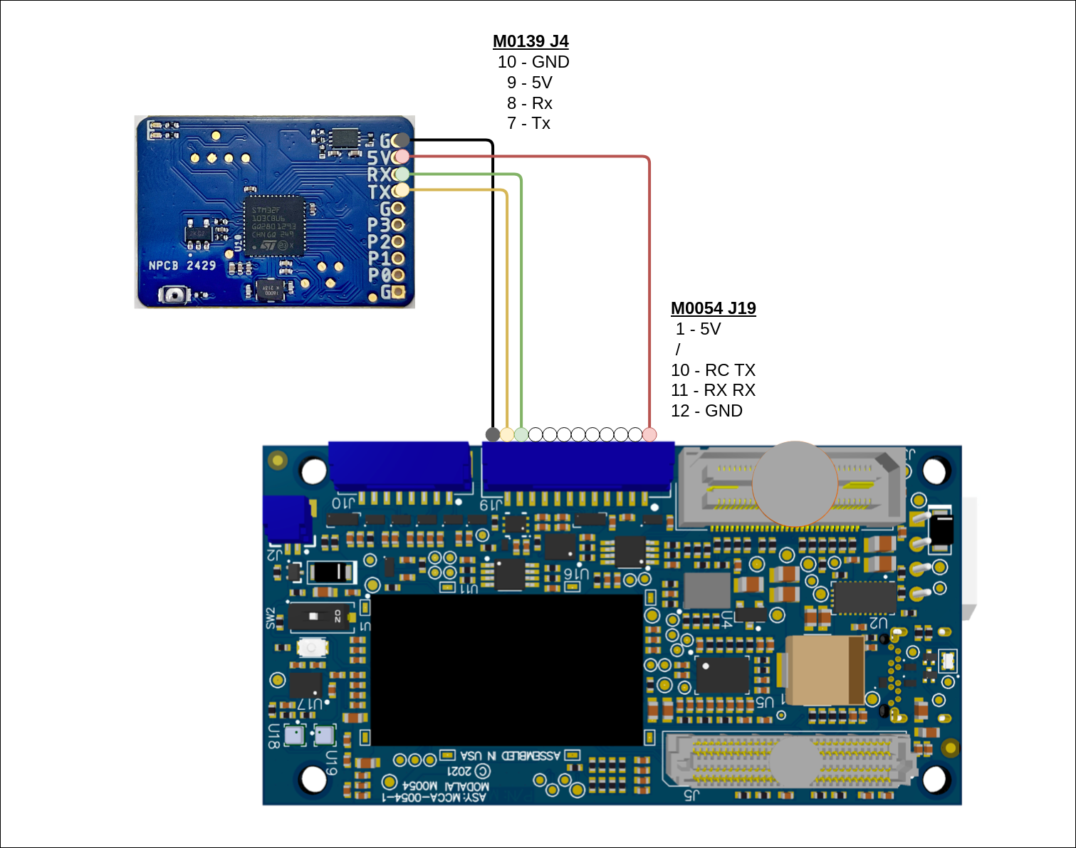
List of Certifications
FCC US radio compliance: For evaluation only; not FCC approved for resale