
ModalAI M0220 Gemini X-Band ELRS Transceiver
ModalAI's M0220 Gemini X ELRS Transceiver
Table of contents
The latest version of the unified firmware is v0.1.4, for instructions on updating see firmware management below.
Summary
Transmitter Compatibility
In general, follow Express LRS guidance, most other devices should be compatible.
VOXL SDK Support
SDK 1.4.1 or newer required. For VOXL SDK usage, please see voxl-elrs.
Dimensions
3D Drawings
TODO
2D Drawings
TODO
Features
| Feature | Details |
|---|---|
| Weight | TODO g |
| HxW | H x W |
| Frequency Bands | 915Mhz, 2.4 GHz |
| Input Voltage | 5VDC, 2A max (TX/RX) |
| Serial Output | CRSF, MAVLink, Custom |
| RF Chip | Dual LR1121, nRF7002 |
| Antenna | |
| Firmware | v0.1.4 |
| MCU | 64 MHz, 32-bit ARM M33 nRF5340 |
| Memory | 512 KB RAM |
| 1MB Flash | |
| 8MB External Flash | |
| Inputs | UART, USB, GPIO, WiFi |
| Outputs | QTY 4 PWM, UART, USB, WiFi, LED |
Hardware
The M0220 is a flexible ELRS transceiver module, meant to be integrated into any hardware project through the inclusion of a single b2b connector, providing a large variety of optional interfaces.
Integrators may choose to use or expose any combination of features or interfaces exposed on the board.
Connector pinout
| Pin | In/Out | Usage | Pin | In/Out | Usage |
|---|---|---|---|---|---|
| 2 | In | 5V | 1 | In | 5V |
| 4 | In | 5V | 3 | In | 5V |
| 6 | In | 5V | 5 | In | 5V |
| 8 | In | 5V | 7 | In | 5V |
| 10 | In | 5V | 9 | In | 5V |
| 12 | In | 5V | 11 | In | 5V |
| 14 | In | 5V | 13 | In | 5V |
| 16 | In | 5V | 15 | In | 5V |
| 18 | In | 5V | 17 | Out | 3V3 Out |
| 20 | In | GND | 19 | In | GND |
| 22 | Out | PWM 1 / FAN CTRL | 21 | Out | V_TEMP |
| 24 | In | GND | 23 | In | GND |
| 26 | Out | PWM 2 / HDPLX DIR | 25 | In | GND |
| 28 | In | GND | 27 | In | GND |
| 30 | Out | PWM 3 | 29 | In | GND |
| 32 | In | GND | 31 | In | GND |
| 34 | Out | PWM 4 | 33 | In | GND |
| 36 | In | GND | 35 | In | SWD IO |
| 38 | Out | UART 1 TX | 37 | In | N RESET |
| 40 | In | UART 1 RX | 39 | In | SWD CLK |
| 42 | In | GND | 41 | In | GND |
| 44 | Out | UART 2 TX | 43 | In | GND |
| 46 | In | UART 2 RX | 45 | In | GND |
| 48 | In | GND | 47 | In | GND |
| 50 | In | GPIO 1 | 49 | In | GND |
| 52 | In | GPIO 2 | 51 | In | GND |
| 54 | In | GPIO 3 | 53 | In | GND |
| 56 | I/O | USB P | 55 | In | VBUS |
| 58 | I/O | USB N | 57 | In | GND |
| 60 | In | GND | 59 | In | GND |
GPIO Configuration
The M0220 configuration GPIOs will be pulled down by default. Use external pullups to configure the desired mode of operation. The configuration below is subject to change.
The M0220 Program and Debug board has jumpers exposed to configure these pins.
| Mode | 1 | 2 | 3 | UART 1 Config | UART 2 Config | USB Mode | PWM/GPIO Usage | ELRS Mode |
|---|---|---|---|---|---|---|---|---|
| Production/Test | 0 | 0 | 0 | MAVLink 8N1@921600 | MAVLink 8N1@921600 | CDC-ECM | PWM | Off |
| Transmitter | 0 | 1 | 0 | CRSF 8N1@921600 | Serial 8N1@9600 | CDC-ECM | FAN CTRL | TX |
| Backpack Transmitter | 0 | 1 | 1 | CRSF HDPLX 8N1@921600 | Serial 8N1@9600 | CDC-ECM | FAN CTRL + HDPLX COM_DIR | TX |
| Receiver | 0 | 0 | 1 | CRSF 8N1@420000 | Serial 8N1@9600 | CDC-ECM | PWM | RX |
| Repeater | 1 | 0 | 0 | MAVLink 8N1@921600 | CRSF 8N1@420000 | CDC-ECM | PWM | Repeater |
| Reserved | 1 | 0 | 1 | Off | Off | CDC-ECM | Off | Off |
| Reserved | 1 | 1 | 0 | Off | Off | CDC-ECM | Off | Off |
| Reserved | 1 | 1 | 1 | Off | Off | CDC-ECM | Off | Off |
These configurations can be changed manually during operation, but on boot the GPIO-determined configuration will be re-applied.
In the future an “override” option may be added to allow the user’s configuration changes to persist.
Antenna Arrangement
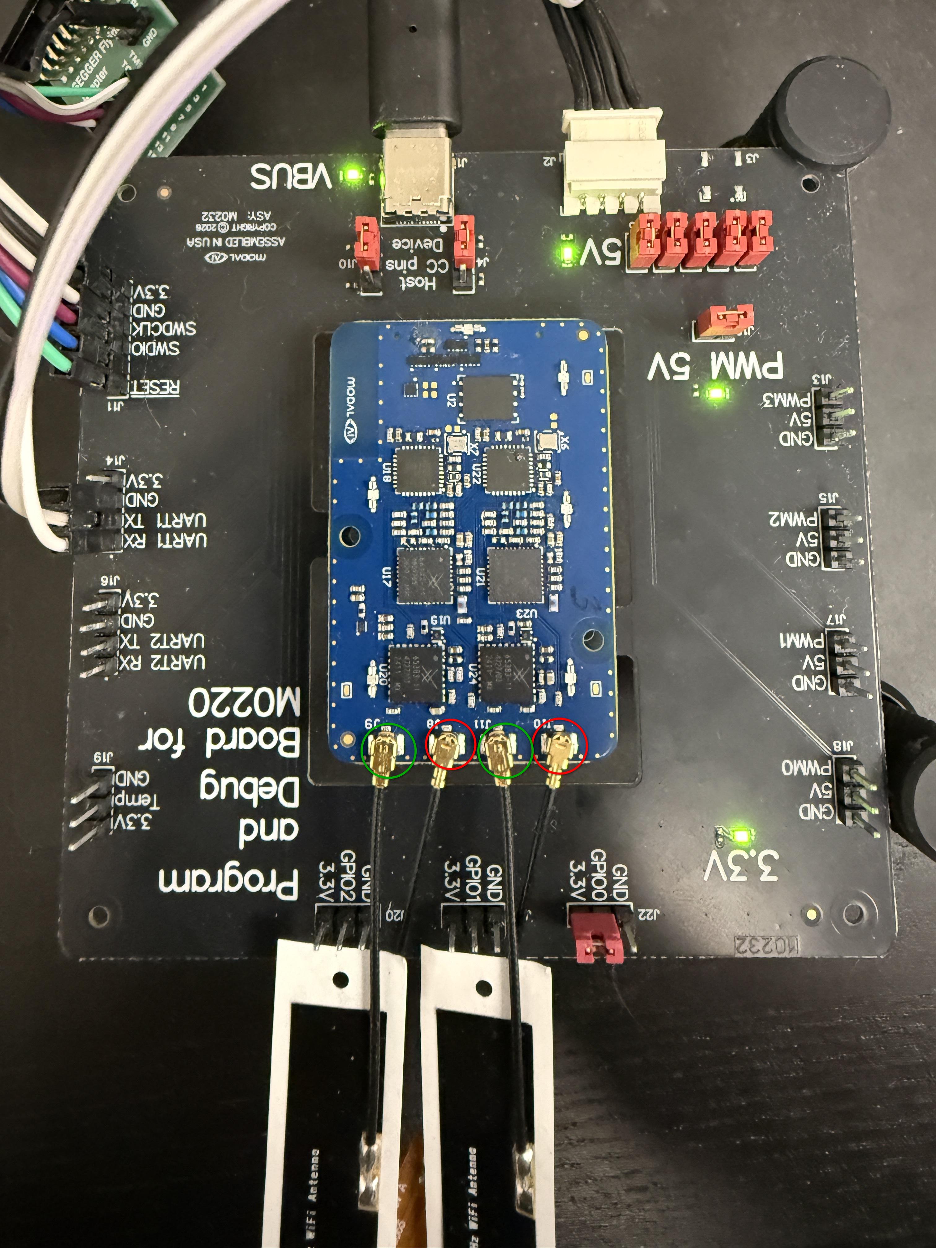
- J10 Antenna 1 - 915 MHz
- J11 Antenna 1 - 2.4 GHz
- J8 Antenna 2 - 915 MHz
- J9 Antenna 2 - 2.4 GHz
ExpressLRS
The main function of the M0220 is as an ExpressLRS-compatible transceiver. The firmware is flexible and allows the user to change all critical configuration on the fly such as receiver/transmitter, v3/v4 compatibility, domain selection, and standard runtime options like ELRS rate, telemetry ratio, antenna mode, and power output.
By default, the transceiver is compatible with all ELRS v4+ devices, use with ELRS v3 devices is still experimental and will likely result in degraded performance.
The ELRS v4+ compatibility above applies to the M0220 only. The M0184 receiver runs ELRS 3.x firmware and requires an ELRS v3 transmitter; see M0184 transmitter compatibility.
Binding
The binding procedure is identical to/compatible with upstream ExpressLRS devices. Using the ‘Bind’ option on a reciever will put it into “binding” mode (the ‘state’ display on the dashboard will show this) until a nearby transmitter uses the ‘Bind’ option to send a brief burst of binding packets to all nearby receivers.
After binding, the modems may take a minute to connect to eachother as the receiver must search through all available ‘Rate’ options for the transmitter.
Configuration
Rate
The ‘Rate’ parameter controls the update rate of the sticks and maximum bandwidth for data passthrough, as well as the receive sensitivy and noise resistance of the link. Increasing the ‘Rate’ will decrease the effective range of the link, but increase the data link’s maximum bitrate.
Rates marked as “Full” send more data per packet, so the bit depth of each channel is increased, but these have lower effective ranges than their standard counterparts.
Power
The transmit power (telemetry power for RX) can be controlled through the ELRS_POWER parameter, and allows setting a precise power output in dBm. Higher transmit powers will result in more range, at the cost of increased heat and power usage.
Telemetry Ratio
The telemetry ratio parameter controls how often a receiver will send data back to the transmitter. These telemetry slots take the place of RC transmissions to the receiver, and therefore cause very brief increases in latency. However, higher telemetry rates will result in more bandwidth for data passthrough (CRSF TLM/MAVLink/Serial Passthrough) as this requires a bidirectional reliable link.
Antenna Mode
The antenna mode parameter controls which modems on the dual-modem board are used. If set to a single modem (Ant 1, Ant 2), only modem 1 or modem 2 will be used, just as if it was a single-modem board. For dual-modem operation, the available options are “Switch” and “Gemini”. “Switch” alternates transmissions on the TX between the two modems, and on the RX both modems listen for the same packet on the same channel. “Gemini” puts each modem on a different channel and transmits on both simultaneously.
Enabling Gemini mode currently will cause a degradation in data passthrough (CRSF TLM/MAVLink/Serial Passthrough) support, particularly at higher rates (200 Hz+). This includes all X-Band rates, which require Gemini. Because of this, the default antenna mode is “Switch” at the moment.
For more information on ExpressLRS see the official documentation.
Web UI
The Web UI provides the most complete set of parameters and configuration options. It also provides a live view of the status of the device.
There are multiple interfaces available to reach the Web UI. The web page is completely self-contained on the device’s firmware, so it can be accessed and fully functional without a connection to the internet.
USB Networking
The CDC-ECM USB interface will only work automatically on Linux or Mac hosts, an upgrade to the CDC-NCM class is planned to provide easier integration with Windows hosts
Connecting a host to the USB port of the device will automatically create a network interface connected to the device.
As of version 0.1.1, the device will always assign itself the IPv4 address 192.168.7.1 on the USB interface. It will also start a DHCP server and assign the host the address 192.168.7.2.
Simply navigate a browser on your host to http://192.168.7.1 to connect to the web UI.
WiFi
The WiFi modem can be used to view the Web UI or create a MAVLink connection to the device.
As of version 0.1.1, the device will always assign itself the IPv4 address 192.168.8.1 on the WiFi interface in AP mode. It will also host its own DHCP server on the AP interface. In STA mode, the WiFi interface will start a DHCP client and wait for an IP lease. Currently, the only place the view the address assigned to the device in STA mode is through the Web UI (probably through the USB interface). Future updates will display this address on the CRSF interface as well, along with supporting mDNS discovery.
The default SSID for the AP is ModalAI M0220 and the default password is ModalAiRobots.
Simply navigate a browser on your host to http://192.168.8.1 to connect to the web UI when connected through the AP.
The Web UI is the only place to set an alternate SSID and/or password for the wifi interface. Use the I/O page and click on the WiFi node in the I/O graph to apply new WiFi configurations.
Note that there are a few concerns with using WiFi and ELRS features simultaneously. Firstly, there is no frequency deconfliction between the two systems; while they will not have huge effects on the performance of the other, there may be a slight increase in received noise on the 2.4 GHz band on both interfaces. Secondly, when WiFi turns on or off, there may be a brief pause in UART output.
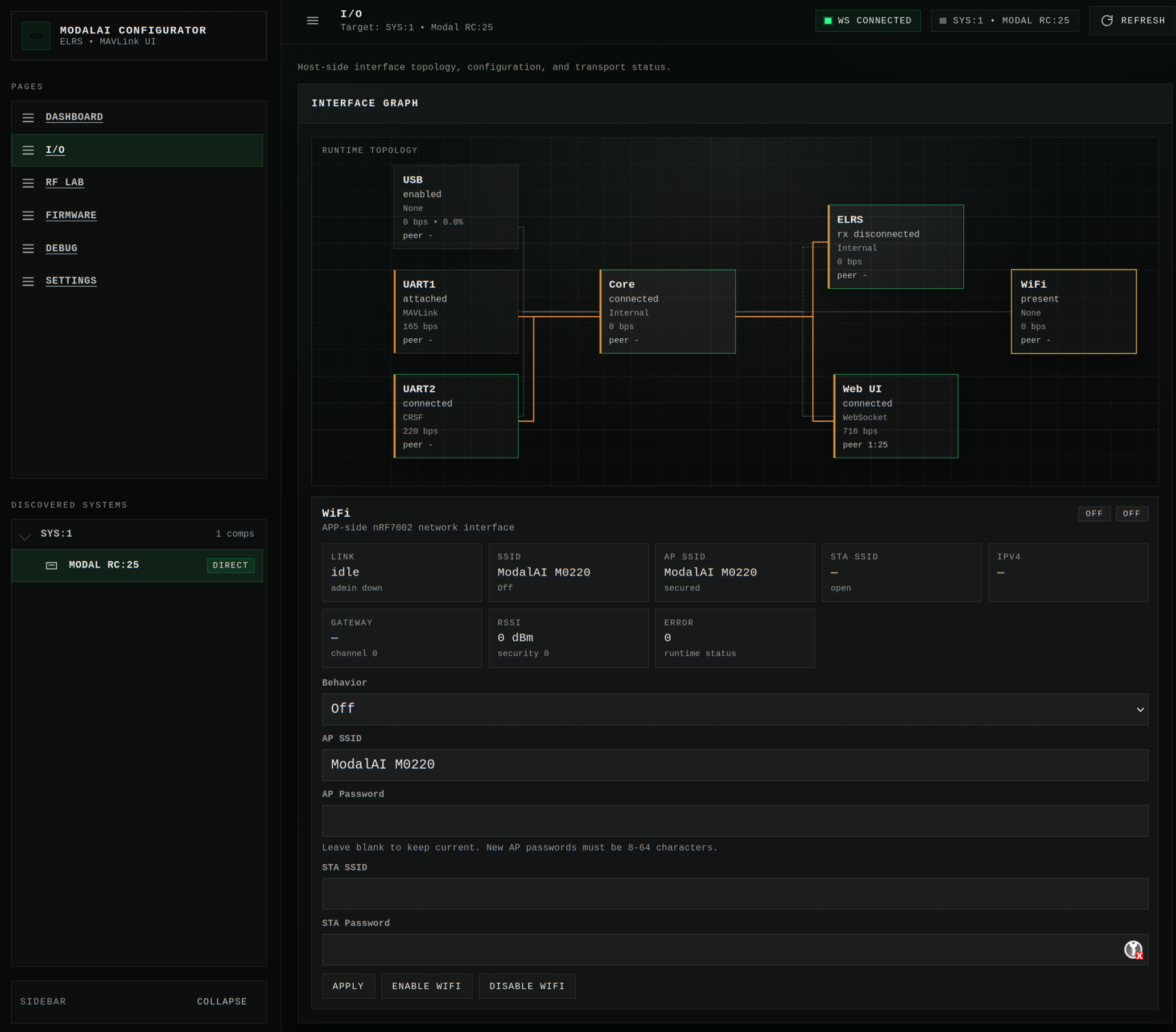
Web UI Features
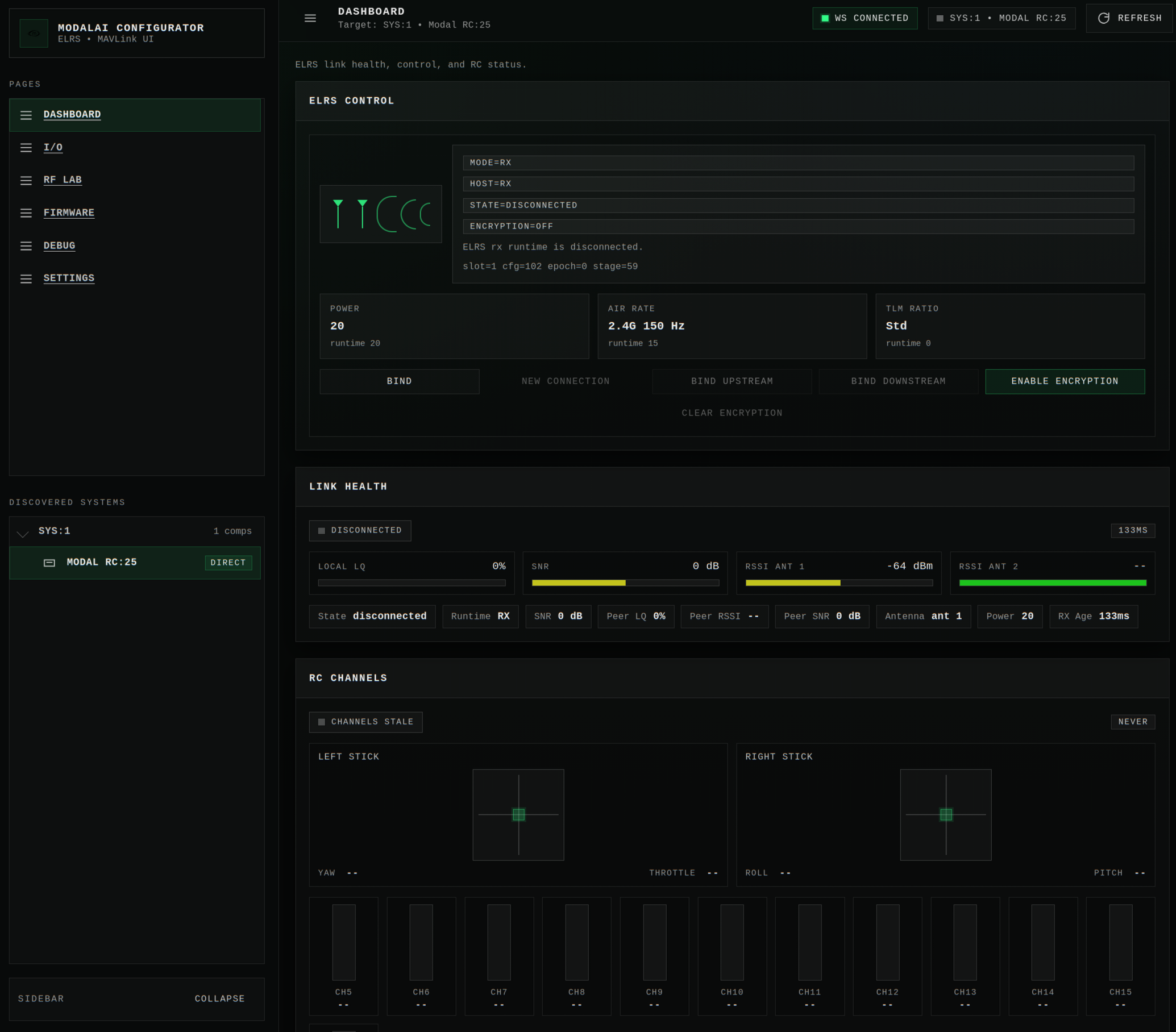
Dashboard
The ‘Dashboard’ is the main user-facing interface with all the controls and status user may need on a constant basis.
I/O
The I/O page allows the user to monitor the flow of RC and Telemetry data, as well as configure the different I/O interfaces.
The features on the I/O page are likely to change in future updates.
Firmware
The firmware page allows you to manage the firmware on the device.
For instructions on updating the device, see the firmware managment instructions below.
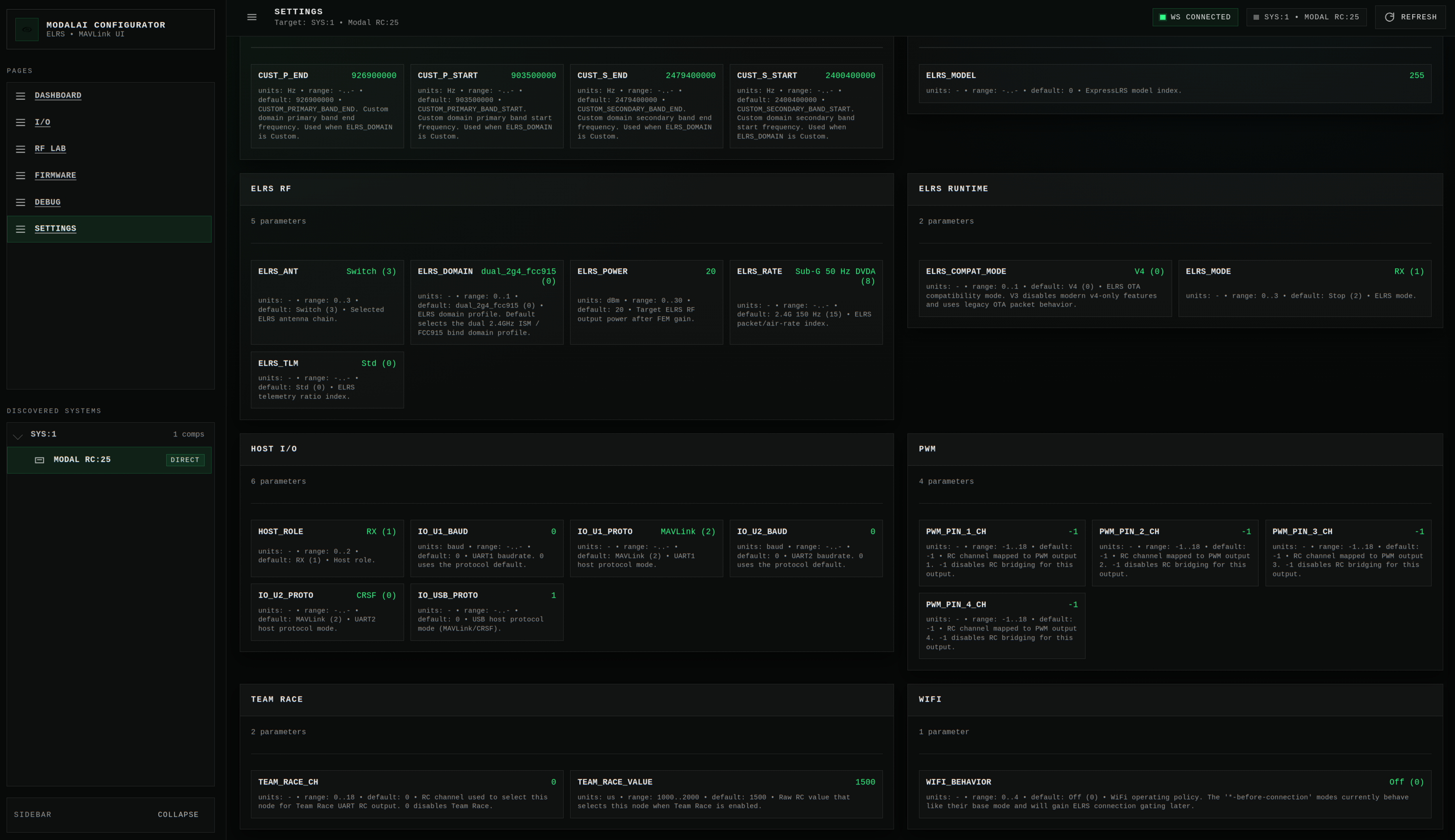
Settings
The ‘Settings’ page has all of the parameters available to control the link and I/O. Almost all of the options available will take effect immediately upon a change.
When you click on a parmeter, there will be a description of the parmamter and an editable field with the value. After changing the value, press enter or click elsewhere on the page and the new value will be applied.
The name of all parameters shown is the MAVLink parameter name, so you can view and edit the same set of parameters through a MAVLink-capable GCS.
UART Interfaces
The M0220 has two independent UART interfaces, which can each be configured to use a custom protocol and baud rate.
All protocol selections have a default baud rate associated with them, which can be overridden by the corresponding _BAUD parameter. Note that the maximimum baud rate supported is 1 Mbps, with standard baud rates (115200, 921600) being more likely to match precisely, due to limitations of the nRF5340 hardware.
The protocols currently available are CRSF, MAVLink, and Serial. You can configure multiple UARTs to use the same protocol if desired.
CRSF Interface / ELRS LUA Script
The CRSF interface uses a default baud rate of 921600 in TX mode, and 420000 in RX mode.
Note that the CRSF interface presents as an RX or TX depending on the HOST_ROLE parameter, not the ELRS_MODE.
The CRSF interface presents a slightly simplified set of parameters compared to the web interface. The full list of controls available on TX modules is below:
- Domain
- RF Band
- Rate
- Telemetry Ratio
- Switch Mode
- Antenna Mode
- Link Mode
- Model Match
- TX Power
- Bind
- WiFi Connectivity
- Enable WiFi
- Enable RX WiFi (not yet functional)
- Encryption
- Enable Encryption
- Clear Encryption
- Encryption Status
- Version ID
Backpack mode
When the UART protocol is set to “CRSF HDPLX”, this modifies the operation of the UART to be compatible with EdgeTX as an external module, through the half-duplex SPort interface. This mode does require an external adapter since the UART on the nRF5340 is not capable of half-duplex or inverted operation. This mode takes over the pin “PWM 2” and uses it to signal if the board is transmitting on the UART, so a simple multiplexer and inverter circuit can be used to connect the M0220 to the external module port.
Note that this mode is only necessary when functioning as an external module, the standard CRSF TX interface works out of the box for an internal module.
MAVLink
The MAVLink interface uses a default baud rate of 921600.
Serial Passthrough
This feature only works between ModalAI Modal-RC products (M0220). v3 Compatability mode must also be disabled for this feature to function.
The ‘Serial’ protocol is special, in that the actual protocol is entirely up to the user. The default baud rate for this protocol is 9600. The ‘Serial’ protocol is used to emulate a serial bridge across an ELRS connection, messages received on a ‘Serial’ interface are sent as a special package through the ELRS link, and then an identical message is sent on the tx output of any ‘Serial’ protocols on the receiving side of the link.
A message is defined as up to 64 bytes, and is delineated by an ‘IDLE’ condition on the UART interface before the beginning and after the end of the packet. If there is an ‘IDLE’ condition in the middle of the packet, it will be sent as two packets on the receiving interface.
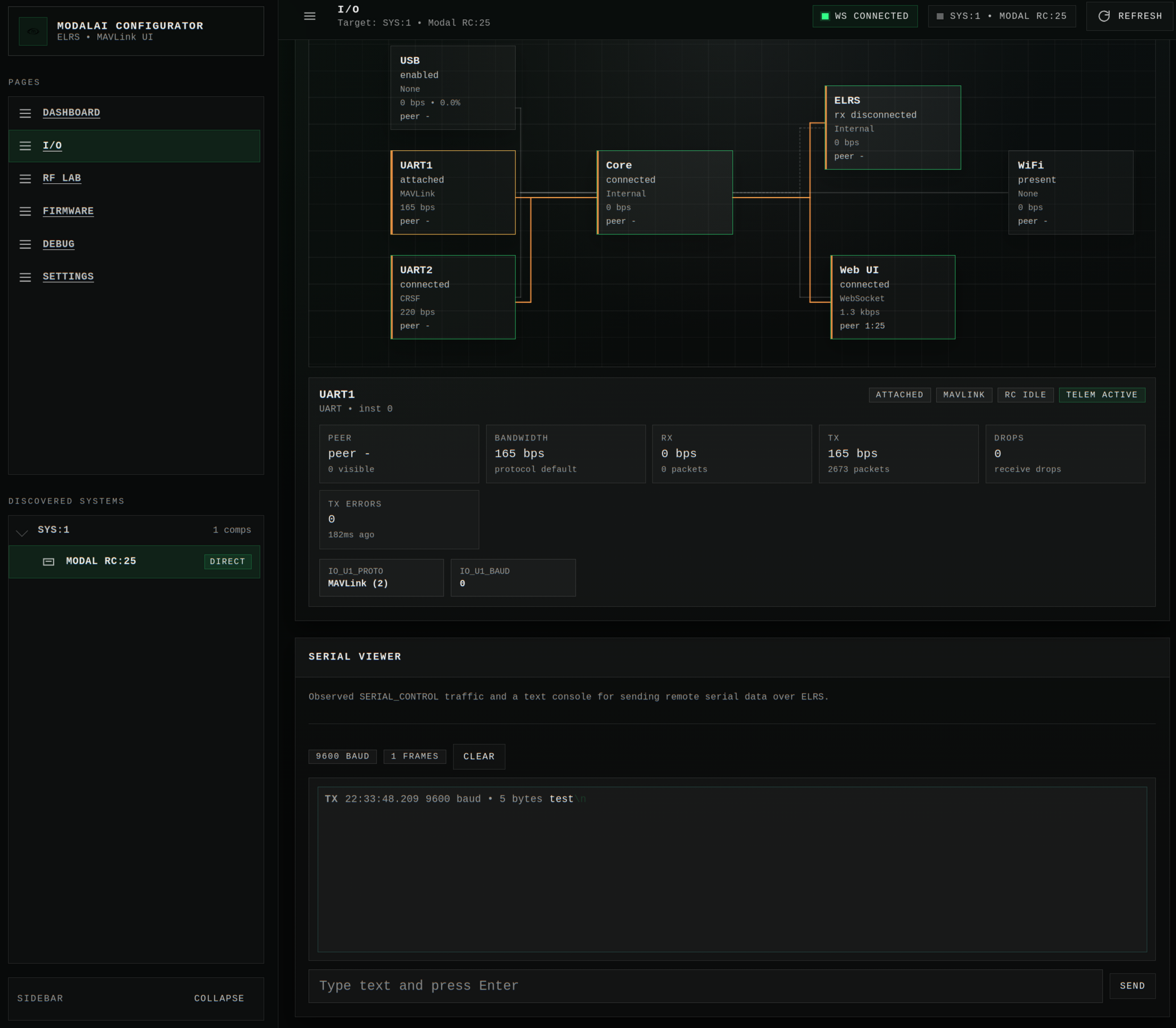
The ‘Serial Viewer’ in the Web UI allows you to view and send these messages manually. You can also send a ‘SERIAL_CONTROL’ MAVLink message to the desired end transceiver and its payload will be sent on the ‘Serial’ UART interface (further documentation on external serial data injection TODO).
Misc. Features
Encryption
This feature only works between ModalAI Modal-RC products (M0220). v3 Compatability mode must also be disabled for this feature to function.
The M0220 features an optional encrypted mode.
Using the encrypted mode is very simple, once a link has been established between two M0220 devices, the user only needs to select ‘Enable Encryption’ on either the Web UI or the CRSF Interface. This will begin an encrypted handshake, key derivation, exchange, and handoff procedure. At the end of this process, the handoff will cause the link to disconnect. After it reconnects (and holds the connection for a few seconds, there may be some additional dropouts during the handover sequence) you should see “Encryption=Active” in the Web UI, or if you refresh the CRSF interface (press ‘RTN’ in the LUA script) you should see “Encryption Status = On” in the “Encryption” menu.
Currently after rebooting the encrypted mode will disable, and the encryption state will show as “Configured”, using the ‘Enable Encryption’ button will start the handoff to encrypted mode immediately, it will not generate new keys.
Encryption Internals
The encrypted link is based on the AES-CTR stream cipher mode. When the encrypted mode is activated, both transceivers generate unique, random values used in an ECDH key derivation sequence to securely exchange an epehemeral key for that connection pair. The key used to protect the link is unique and it is not possible for multiple nodes to connect to a transmitter with the encrypted mode active.
A secondary AES keystream (based on a different securely-derived key) is generated in parallel to the main keystream and is used to seed an infinitely-long secure frequency hopping sequence.
In order to retain the strongest resistance to cryptanalysis by reducing the probability of repeated keystreams, it is suggested to rotate encryption keys within ~100 flight hours of usage, or weekly. Any bind action automatically clears stored keys and new keys will be generated on the next ‘Enable Encryption’.
PWM
The M0220 supports up to 4 PWM outputs when configured as a receiver. Each PWM output can be independently assigned to track the value of a particular channel using the corresponding PWM_PIN_X_CH parameter. When active, the PWM output pin will assert high for the number of microseconds corresponding to the value of the channel as shown on the dashboard (1000..2000), and then stay low for the remainder of the 50 Hz frame.
If the parameter is set to ‘-1’, then the pin is considered disabled. If the parameter is set to any other value, then the output PWM value of that pin will track the channel set by the parameter. The selected channel will be highlighted in the dashboard of the web interface.
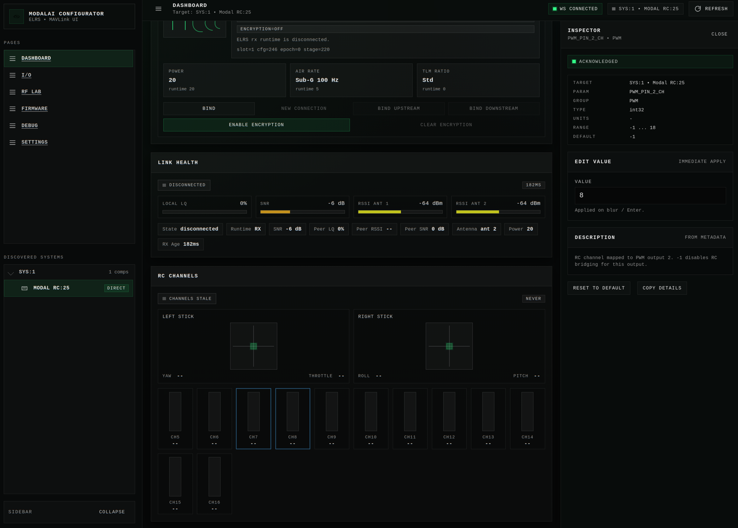
Future development will include more options for PWM output modes, currently on 50 Hz servo control is supported.
TeamRace
The ExpressLRS TeamRace feature allows a user to connect multiple receivers to a transmitter at once, and let the value of an RC channel determine which receiver is under control. See the ExpressLRS Team Racing documentation for more information on the feature.
The parameter TEAM_RACE_CH controls the channel used for TeamRace (a value of 0 disables the feature), and the TEAM_RACE_VALUE parameter sets the value (in servo control units 1000..2000) at which the receiver will be considered active. If TeamRace is active and the channel is not equal to the specified value, UART RC output will stop and telemetry transmission to the transmitter will cease. The selected channel will be highlighted in the dashboard of the web interface.
Repeater
The ExpressLRS Repeater mode is in an early alpha stage.
The Repeater feature allows any M0220 device to connect to both a receiver and transmitter simultaneously, allowing RC control and telemetry to be repeated through the M0220. This can be used to increase operational range or copy telemetry/control across multiple transmitters.
Custom Domain
The M0220 is provided as a development platform, it is your responsibility to ensure the operation of the modems is compliant with all relevant rules and regulations for your jurisdiction.
Currently the default configuration of the M0220 is only compatible with the regulatory jurisdiction of the FCC, particularly for 915 MHz operation.
The custom domain feature lets you customize the center frequencies of the lowest and highest frequency channels for each supported band. Currently the number of channels used is calculated based on the optimal spacing between channels in each frequency band. The parameters used to control the custom domain are:
CUST_P_ENDThe high frequency of the primary (sub-gig) band.CUST_P_STARTThe low frequency of the primary (sub-gig) band.CUST_S_ENDThe high frequency of the secondary (2.4 GHz) band.CUST_S_STARTThe low frequency of the secondary (2.4 GHz) band.
Also, ELRS_DOMAIN should be set to custom to activate this feature.
If your regulatory environment requires listen-before-talk (LBT) or a set number of FHSS channels, you will need to modify the firmware.
RF Testing
You may note the ‘RF Lab’ page is disabled in the Web UI by default. In order to use this page you must flash the rf-lab firmware, which does not include support for ELRS. Instructions for managing firmware can be found below.
The ‘RF Lab’ page allows you to independently control test signals out of each modem, or send and receive test packets on each modem.
When using the ‘RF Lab’, select the desired RF parameters for your test signal, and then select a signal type to start transmitting. Press ‘Stop’ to cease the transmission.
The available RF parameters are:
| Parameter | Min | Max |
|---|---|---|
| Frequency | ||
| Bandwidth | ||
| Power | 30dBm | |
| SF | 5 | 12 |
| CR | 4/5 | 4/8 |
| Preamble | 6 | |
| Sync length |
The output signals available are:
- CW
- Modulated carrier
- Continuous packet (packets are sent one after the other, there will be a small gap in between packets)
- Single Packet
You can use the payload interface to send and receive single packets. Set up the rx parameters on the receiving modem, then press ‘Arm RX’, which will wait for a single packet to be received, then display it on the modem card. Enter identical parameters on the transmitting modem, and your desired hexadecimal payload, then press ‘Send’ to see your packet received on the other modem.
Each modem will display its reported temperature, and the VDET measurement from the 900 MHz FEM, along with a temperature measurement from the board thermistor. The modem temperatures will not start to log until a signal has been transmitted from that modem.
Disabling the ‘Power Limit’ feature allows you to increase the maximum allowed INPUT power into the external PA. Increasing the power beyond this limit will NOT increase the conducted output power. It will only decrease the signal quality and damage the RF hardware.
Updating and FW Management
There are a few options for flashing firmware onto the device. All function through the same mechanism, which is using MAVFTP to stage new firmware binaries to special psuedo-files on the device, then on reboot the bootloader will detect the staged firmware and safely attempt to swap and test the new firmware. If any part of this process fails, the M0220 will remain on the old version unharmed. The A/B firmware manager does mark new firmware as good, and erases the old firmware, as soon as the first boot finishes successfully on the new version, so do not flash untested firmware if you do not have access to the debug hardware necessary to recover the device on failure.
Due to hardware limitations, the update process can take a long time, approximately 10 minutes total (6-8 minutes for staging and a 1-2 minute reboot). Make sure the connection to the device is stable and avoid rebooting the device during the process. Failures during update process will not brick the device but if it fails for any reason you will need to start over.
When selecting a firmware image to update, there are two properties which matter. Firstly the board defines hardware the firmware bundle is compatible with, this must match your current firmware or the update will be rejected. Secondly there is the profile, most users will want the ‘Standard’ profile which includes all relevant ELRS features; however, you can flash bundles with a different profile at any time if you want a different feature set.
Web UI Manual Updates
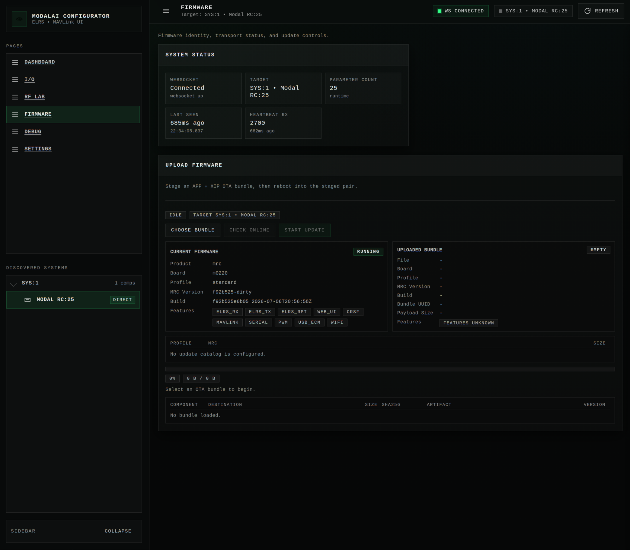
The easiest way to update if you have access to firmware bundle file you want to update to (“*.mrcb”) is to use the ‘Firmware’ page on the web interface. Simply select your firmware file using the ‘Choose Bundle’ button, then ‘Start Flashing’ if everything looks correct. You will be able to compare the new and old firmware side-by-side.
The progress bar will show the status the flashing operation. This will take a while. Once the flashing operation completes, the device will check the firmware and, if acceptable, it will reboot and swap the running firmware. You will lose connection for 1-3 minutes as this process completes. Once you can connect to your device again the update is complete, and you should see the details of the newly-flashed firmware in the ‘Current Firmware’ column of the ‘Firmware’ page.
Automatic Updates
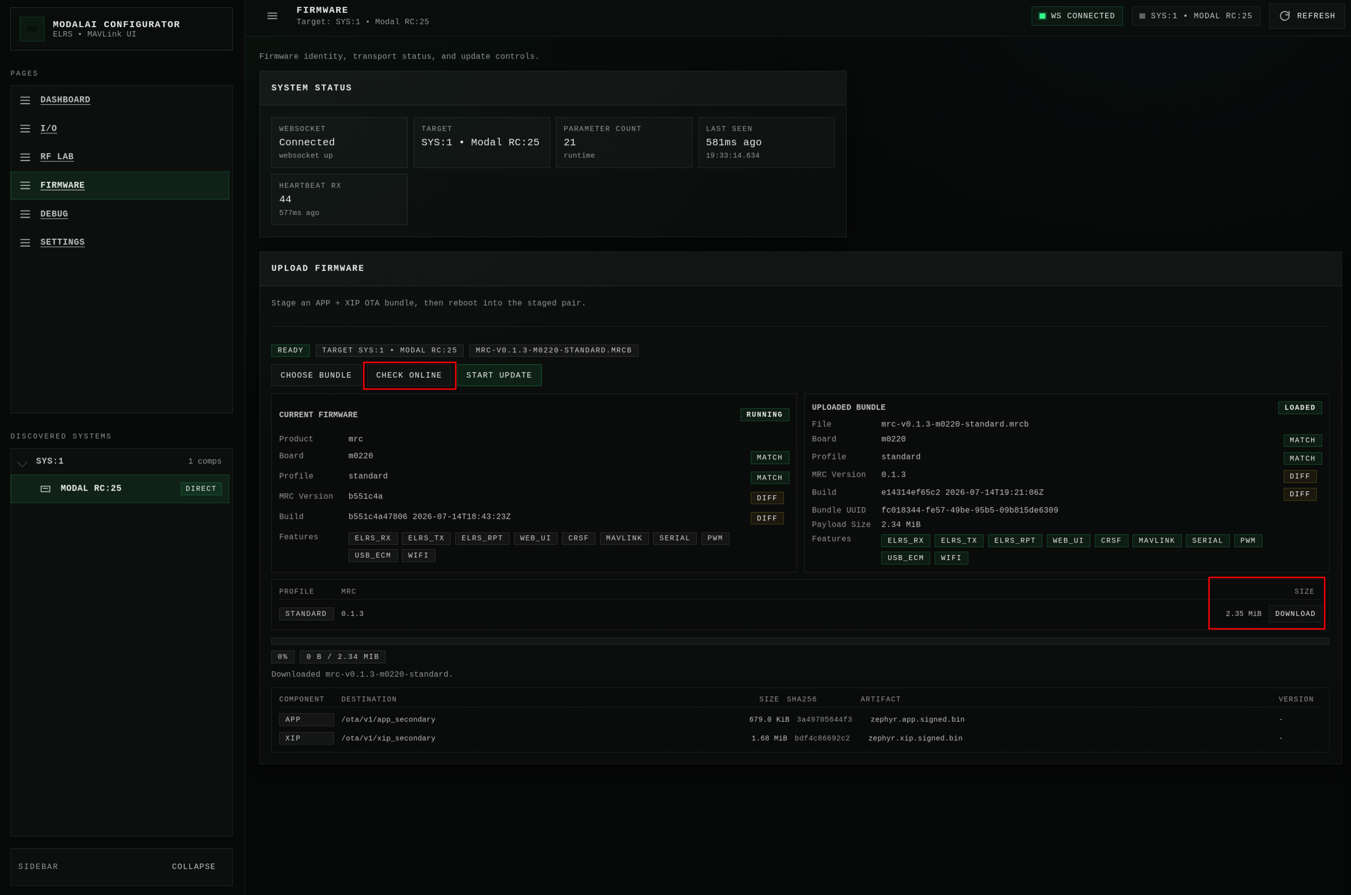
ModalAI firmware release will be automatically published and available for and M0220 to download. If you are connected the WebUI and also have an internet connection available, you can use the ‘Check Online’ button to show available firmware releases that are newer than the firmware running on the device. If updates are available, compatible firmware releases will be listed below the firmware comparision card. You can use the ‘Download’ button to grab the new firmware and prepare it for upload. The downloaded firmware will then be shown in the ‘Uploaded Bundle’ column of the comparison, and if everything looks good press ‘Start Update’ to begin the update process.
UART updates with voxl-elrs
To update an M0220 through a CRSF UART connection, use the voxl-elrs utility. This is most useful for M0220 transceivers integrated into larger systems as standard CRSF-based ELRS devices (for example EdgeTX or VOXL). It only works over UARTs configured for the CRSF protocol.
From SDK 1.8.0 (voxl-elrs 1.2.2 and newer), voxl-elrs writes M0220 firmware over SMP (the MCUboot serial protocol). The input is still an MRC bundle; the app and XIP images are written to the primary slots, and both MCUboot hashes are checked before the device is reset. M0220 firmware is not bundled with voxl-elrs, so download the bundle you want to install first.
voxl-elrs comes pre-installed with the VOXL SDK. To run the update from a Linux host, build it natively. This requires CMake 3.22 or newer, pkg-config, cJSON, libcurl, and a C toolchain:
git clone https://gitlab.com/voxl-public/voxl-sdk/utilities/voxl-elrs.git
cd voxl-elrs
cmake --workflow --preset native
The native build includes online firmware catalog support, which needs libcurl; configure with -DBUILD_ONLINE_UPDATE=OFF to build without it. The executable is written to ./build/src/voxl-elrs.
Run ping first to confirm the device is reachable, then upload the bundle:
./build/src/voxl-elrs -p /dev/ttyUSB0 ping
./build/src/voxl-elrs -p /dev/ttyUSB0 upload-firmware <firmware.mrcb>
For a transmitter connected directly (not through EdgeTX), add -T:
./build/src/voxl-elrs -T -p /dev/ttyUSB0 upload-firmware <firmware.mrcb>
To reach an internal transmitter (not an externally mounted backpack) through an EdgeTX handset, select the ‘USB Serial’ option on the handset when connecting the USB cable and pass -E:
./build/src/voxl-elrs -E -p /dev/ttyUSB0 ping
SMP updates need the updated M0220 bootloader.
voxl-elrstalks to the bootloader at 420000 baud for HWID 0x01 and 921600 otherwise. Older bootloaders always run at 921600, so a receiver update at 420000 needs the updated bootloader.
If an upload is interrupted or a hash check fails, the device stays in its bootloader (recovery). It is not reset and there is no fallback to the old MAVLink FTP path. Recover it by uploading again with an explicit smp, which does not need CRSF discovery (add -T for a transmitter):
./build/src/voxl-elrs -p /dev/ttyUSB0 upload-firmware <firmware.mrcb> smp
The legacy MAVLink FTP upload remains available as voxl-elrs update-mrc <bundle>.
SDK 1.6 and older ship voxl-elrs 1.1.7 or earlier, which cannot update an M0220. On those releases, use the web interface or build voxl-elrs on a host as described above.