Cable Datasheets
ModalAI has various cables used by its systems. Below captures the cables by part number and provides pinouts and other relevant information. The Cable User Guide page has information on finding the right cable for your system and how to make your own cables with specific examples.
Note when voltages are listed as “Source” that side is an Output voltage for use by a “Load” or device on the other side. Be sure to check that two sources are not shorted together without first verifying from ModalAI if they are from the same prime source. Weights provided in grams are subject to +/-0.25 gram tolerances.
Table of contents
Cable Catalog
| Cable (Click to jump to section) | Category | Description | Purchase |
|---|---|---|---|
| MCK-M0018-1 | Cable Kit | Flight Core Cable Kit ~ END OF LIFE ~ | Purchase |
| MCK-M0087-2 | Cable Kit | Flight Core V2 Cable Kit | Purchase |
| MCBL-00001 | Power | VOXL Flight and VOXL/VOXL 2 to Power Module Cable | Purchase |
| MCBL-00003 | Power | Flight Core to Power Module Cable | Purchase |
| MCBL-00004 | Signal-PWM | PWM Output Cable | Purchase |
| MCBL-00005 | Signal-UART/RC+PWR | RC Input Cable (Spektrum) | Purchase |
| MCBL-00007 | Signal-UART | VOXL to Flight Core/VOXL ESC Serial Cable | Purchase |
| MCBL-00008 | Signal-UART | VOXL to Flight Controller TELEM port | Purchase |
| MCBL-00009 | USB | 4-pin JST GH to USBA Female Cable | Purchase |
| MCBL-00010 | USB | 4-pin JST GH to micro USB Female Cable | Purchase |
| MCBL-00011 | Power | VOXL-PM-Y for Flight Deck R0/R1 Cable | Purchase |
| MCBL-00013 | Signal-UART | VOXL Flight to VOXL ESC Cable (cross over) | |
| MCBL-00014 | Signal-UART | Flight Core to VOXL ESC Cable (cross over) | Purchase |
| MCBL-00015 | Signal-Multi | 4pin-JST-GH-to-4pin-JST-GH cable | Purchase |
| MCBL-00016 | Signal-Multi | 6pin-JST-GH-to-pigtail break out cable | Purchase |
| MCBL-00017 | Power | 5V Stand Alone Dongle Cable, v1 | |
| MCBL-00018 | Signal-UART/RC+PWR | RC Input Cable, Servo (S.Bus, FrSky) | Purchase |
| MCBL-00020 | Signal-Multi | USB Cable, 4-pin Molex Picoblade to 4-pin JST-GH, ArduCam | |
| MCBL-00021 | Signal-UART/RC+PWR | RC Input Cable, FrSky R-XSR to Flight Core / VOXL Flight | |
| MCBL-00022 | USB | USB3 10-pin JST cable | Purchase |
| MCBL-00024 | Power | Power Module to Stand Alone Modem Cable | Purchase |
| MCBL-00025 | Signal-UART | LTE v2 to Flight Core Telemetry | |
| MCBL-00028 | Signal-UART/GNSS+I2C+PWR | Seeker GPS cable | |
| MCBL-00029 | Signal-UART | VOXL 2 or QC Flight RB5 to ESC cable / VOXL 2 to ESC | Purchase |
| MCBL-00031 | Signal-Multi | 6 pin-JST-GH-to 6-pin-JST-GH passthrough, Breakout | Purchase |
| MCBL-00041 | USB | 4-pin JST GH to USBA Female Cable | Purchase |
| MCBL-00048 | Signal-UART/GNSS+I2C+PWR | Flight Core v2 DroneCode Compliant 6-pin JST to 6-pin SHR | |
| MCBL-00061 | Signal-UART/RC+PWR | VOXL 2 to VOXL 2 I/O | Purchase |
| MCBL-00062 | Power | Flight Core v2 Power Cable | Purchase |
| MCBL-00063 | Signal-UART | Flight Core v2 UART ESC Cable | |
| MCBL-00064 | Signal-UART/RC+PWR | VOXL 2 IO RC Input Cable, Servo (S.Bus, FrSky) | Purchase |
| MCBL-00065 | Signal-UART/RC+PWR | VOXL 2 IO RC Input Cable, FrSky S.BUS R-XSR | |
| MCBL-00066 | Signal-UART | VOXL 2 Add-on UART 6-pin JST to FlightCore 6-pin JST (cross over) | Purchase |
| MCBL-00067 | Signal-UART | VOXL 2 Add-on UART 4-pin JST to FlightCore 6-pin JST (straight) | Purchase |
| MCBL-00068 | USB | VOXL 2 4-pin JST USB to Doodle Labs Helix | Purchase |
| MCBL-00069 | Signal-UART | VOXL 2 ESC 4-pin JST UART to Custom TMotor F55A ESC | Purchase |
| MCBL-00070 | Signal-Multi | VOXL 2 12-Pin JST GH Breakout Cable | |
| MCBL-00071 | Signal-Multi/USB | 4-Pin JST GH Breakout Cable | |
| MCBL-00072 | USB | VOXL 2 10-pin JST USB to Boson RHP-BOS-VPC3-IF | Purchase |
| MCBL-00076 | Signal-UART/GNSS+RC+PWR | Starling/Sentinel GPS + RC UART cable | Purchase |
| MCBL-00078 | Power | XT30U-M to Pigtail 150mm | |
| MCBL-00080 | USB | VOXL 2 10-pin JST USB3 to 4-pin JST USB2 | Purchase |
| MCBL-00081 | Signal-UART | VOXL 2 Mini 12-pin JST to 6-pin DF13 ESC UART | |
| MCBL-00082 | Signal-UART | VOXL 2 Mini 12-pin JST to 4-pin JST ESC UART | |
| MCBL-00083 | Signal-Multi | VOXL 2 8-Pin JST GH Breakout Cable | |
| MCBL-00085 | USB+PWR | VOXL 2 10-Pin JST USB to Doodle Labs RM-2025-62M3 Cable | Purchase |
| MCBL-00086 | Signal-UART/GNSS+RC+PWR | Sentinel Holybro (Pixhawk) GPS + RC UART Cable | |
| MCBL-00088 | Power | XT60-M to Pigtail 150mm | |
| MCBL-00089 | Signal-UART/GNSS+ESC+RC | Stinger (“Full VOXL 2 Mini Breakout”) GPS + ESC + RC Cable | Purchase |
| MCBL-00090 | USB-to-UART | ModalAI USB to Serial UART JST-SH Cable (Console Debug) | |
| MCBL-00091 | USB-to-UART | ModalAI USB to Serial UART JST-GH Cable (ESC Tools/HWIL) | |
| MCBL-00092 | Power | JST RCY Receptacle Cable Assy Red/Black | |
| MCBL-00093 | Power | JST RCY Plug Cable Assy Red/Black | |
| MCBL-00094 | USB | 10-Pin JST GH USB2 Breakout Cable/Pigtails | |
| MCBL-00095 | Power | VOXL-PM-Y for Legacy ToF M0169 | Purchase |
| MCBL-00098 | Signal-Multi | 3-Pin JST GH Sub-Pop 1&3 Breakout Cable | |
| MCBL-00099 | Signal-Multi | 4-Pin JST GH Sub-Pop 1&4 Breakout Cable | |
| MCBL-00100 | Signal-Multi | 4-Pin JST GH Sub-Pop 2&3 Breakout Cable | |
| MCBL-00103 | Power | XT60EW-M Bulkhead to Pigtail 80mm | |
| MCBL-00104 | USB | ModalAI Boson USB Host Programming Cable | |
| MCBL-00105 | Signal | 8-Pin JST SH to 8-Pin JST SH Extension | |
| MCBL-00106 | Power | XT30U-F to Banana Plugs 300mm | |
| MCBL-00107 | USB | VOXL 2 4-pin JST USB to Boson RHP-BOS-VPC3-IF | |
| MCBL-00109 | Power | XT30U-F Test Mode Power Jumper | Purchase |
| MCBL-00110 | Power | XT60-M to Pigtail 120mm | |
| MCBL-00111 | Signal-Multi | 8pin-JST-GH-to-8pin-JST-GH cable | |
| MCBL-00112 | Power-Multi | Molex 4-Pin MicroOne to Pigtail, 100mm | |
| MCBL-00113 | Power | Molex 4-Pin MicroOne to Pigtail, Sub-Pop 1&2, 100mm | |
| MCBL-00114 | Power | JST SFHR-L to SFHR-L VBAT Extension Cable | |
| MCBL-00115 | Power | JST SFHR-L to XT30U-M VBAT Extension Cable | |
| MCBL-00116 | Power | JST SFHR-L to XT60-M VBAT Extension Cable | |
| MCBL-00117 | Signal-UART/VTX-PWR | VOXL 2 MINI UART + VBAT to HD-Zero VTX Cable, 100mm | |
| MCBL-00118 | Signal-UART/VTX-PWR | FC/OSD UART + VBAT to HD-Zero VTX Cable, 100mm | |
| MCBL-00119 | Signal-PWM/PWR | LED bar Cable PWM Pigtails SYR + SL, 100mm | |
| MCBL-00120 | Signal | VOXL 2 8-Pin JST GH SPI Adapter Cable to JST 6-Pin SH | |
| MCBL-00121 | USB | 10-pin JST GH to USBA Female Cable | |
| MCBL-00122 | Signal-Multi | 6-Pin JST GH Sub-Pop 2, 3, & 6 Breakout Cable | |
| MCBL-00123 | Signal-Multi | 2-Pin Molex SL Receptacle Breakout Cable | |
| MCBL-00124 | Signal-Multi | 2-Pin Molex SL Plug Breakout Cable | |
| MCBL-00125 | Power | JST SFHR-T-K to SFHR-T-K 3.8V 1S VBAT Extension | |
| MCBL-00126 | Power | JST SFHR-T-K breakout to Pigtail, 100mm | |
| MCBL-00127 | Power | JST SFHR-L to Molex SL Plug VBAT Power Cable | |
| MCBL-00128 | Signal | Sparrow 10-pin JST SH to Dual ToF Pill 5-pin SH | |
| MCBL-00129 | Signal-UART/ESC+RC | Stinger (VOXL 2 Mini) ESC + RC Cable | |
| MCBL-00130 | Signal | VOXL 2 Dronecode 6-pin JST GH I2C to 3-Pin JST SH | |
| MCBL-00131 | Signal | 3-Pin JST SH to 3-Pin JST SH Straight Through | |
| MCBL-00132 | Power | Molex 4-Pin MicroOne to JST SFHR-T-K 3.8V 1S VBAT, 80mm | |
| MCBL-00133 | Signal-Multi | 4pin-JST-GH-to-4pin-JST-GH Cross-Over cable, 50mm | |
| MCBL-00137 | Power | JST SFHR-L VBAT Pigtail Cable, 100mm | |
| MCBL-00138 | Signal-RC/PWM Type 2-B | Stinger: PWM Cable Type 2-B Receptacle | |
| MCBL-00146 | Power | XT60-M to Dual JST SFHR-L VBAT Y-Cable, 50mm | |
| MCBL-00151 | Signal | VOXL 2 8-Pin JST GH UART to BraveF7 OSD Cable, 75mm | |
| MCBL-00152 | USB | 4pin-JST GH to 4pin-JST SH cable, 50mm | |
| MCBL-00159 | Power | Molex Mini-SPOX to 6-Pin JST GH for Doodle RM-2025-62M3 | |
| MCBL-00160 | Signal | VOXL 2 Mini 8-pin JST GH UART to DroneCode 6-pin JST SH | |
| MCBL-00162 | USB | USB2 Type-A Male Data Only Cable to JST GH 4-pin, 200mm | |
| MCBL-00211 | Power | VOXL-PM-Y for FCv2 Flight Deck Cable | |
| MCBL-00218 | Signal-UART/RC+PWR | RC Input Cable, Servo (S.Bus, FrSky), Flight Core V2 | Purchase |
| MCBL-00221 | Signal-UART/RC+PWR | RC Input Cable, FrSky R-XSR to Flight Corev2 |
Related Accessories
| Accessories | Description |
|---|---|
| MCCA-M0022) | PWM Breakout PCB |
MCK-M0018-1 END-OF-LIFE
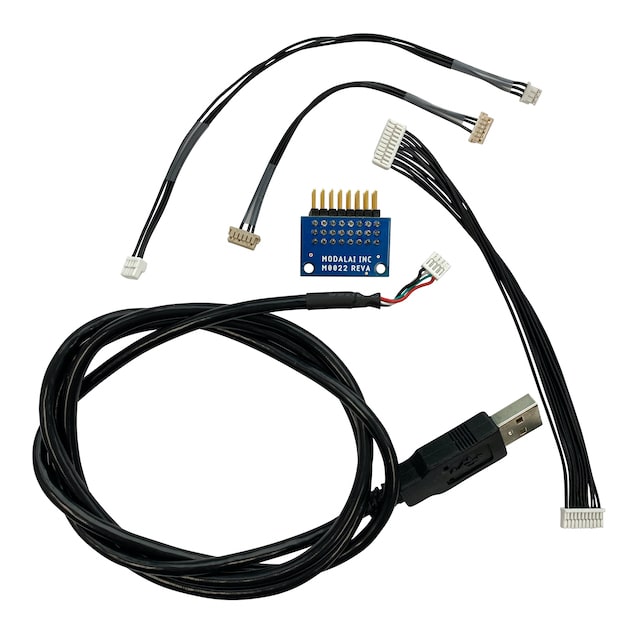
Description:
- Flight Core Cable Kit
Contains:
- PWM Break Out Board (MCCA-M0022)
- MCBL-00004 - PWM breakout cable
- MCBL-00005 - RC Input Cable
- MCBL-00010 - JST to microUSB female (MCBL-00006, not provided, shown in image)
- MCBL-00007 - VOXL to Flight Core Serial Cable (provides MAVLink connection over UART between VOXL and Flight Core)
Buy:
MCK-M0087-2
Description:
- Flight Core V2 Cable Kit, See Contents List Below:
Contains:
- PWM Break Out Board (MCCA-M0022)
- MCBL-00004 - PWM breakout cable
- MCBL-00005 - RC Input Cable
- MCBL-00008 - VOXL to Flight Controller TELEM port
- MCBL-00010 - JST to microUSB female
- MCBL-00016 - 6pin-JST-GH-to-pigtail break out cable
- MCBL-00062 - Flight Core v2 Power Cable
- MCBL-00063 - Flight Core v2 UART ESC Cable
Buy:
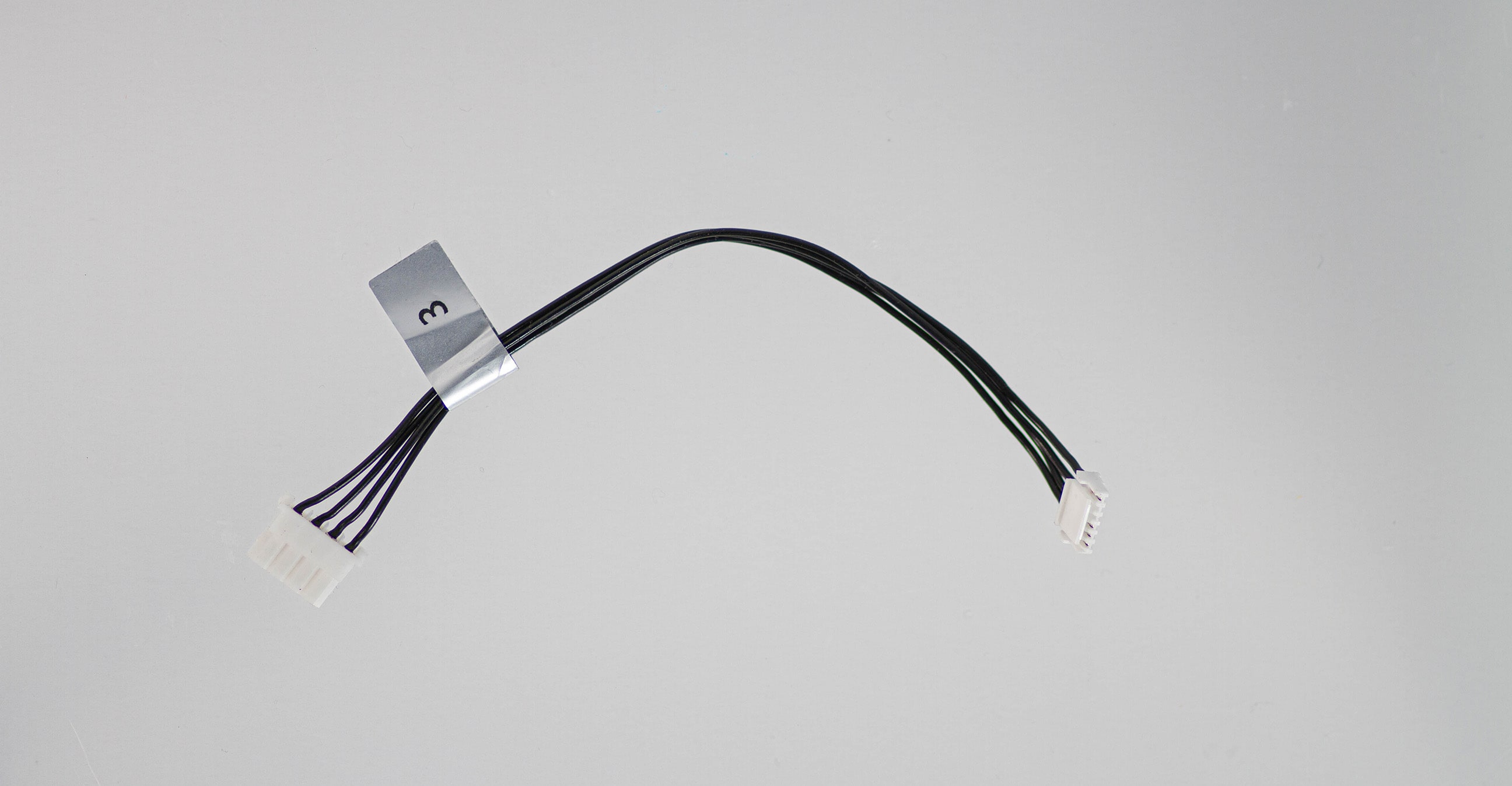
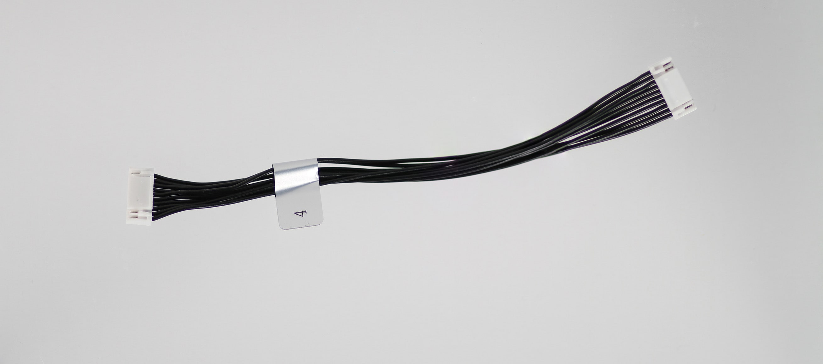
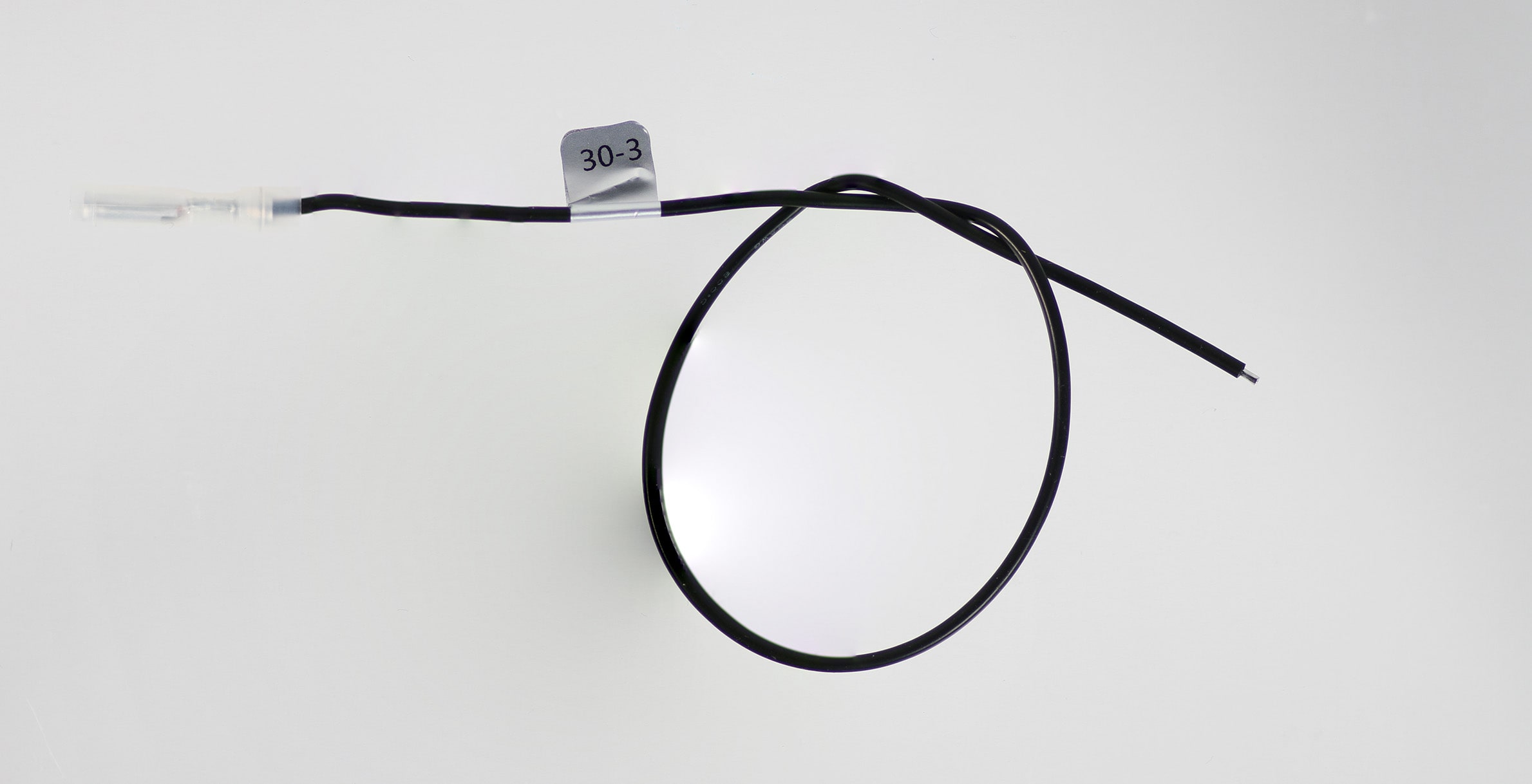
MCBL-00001
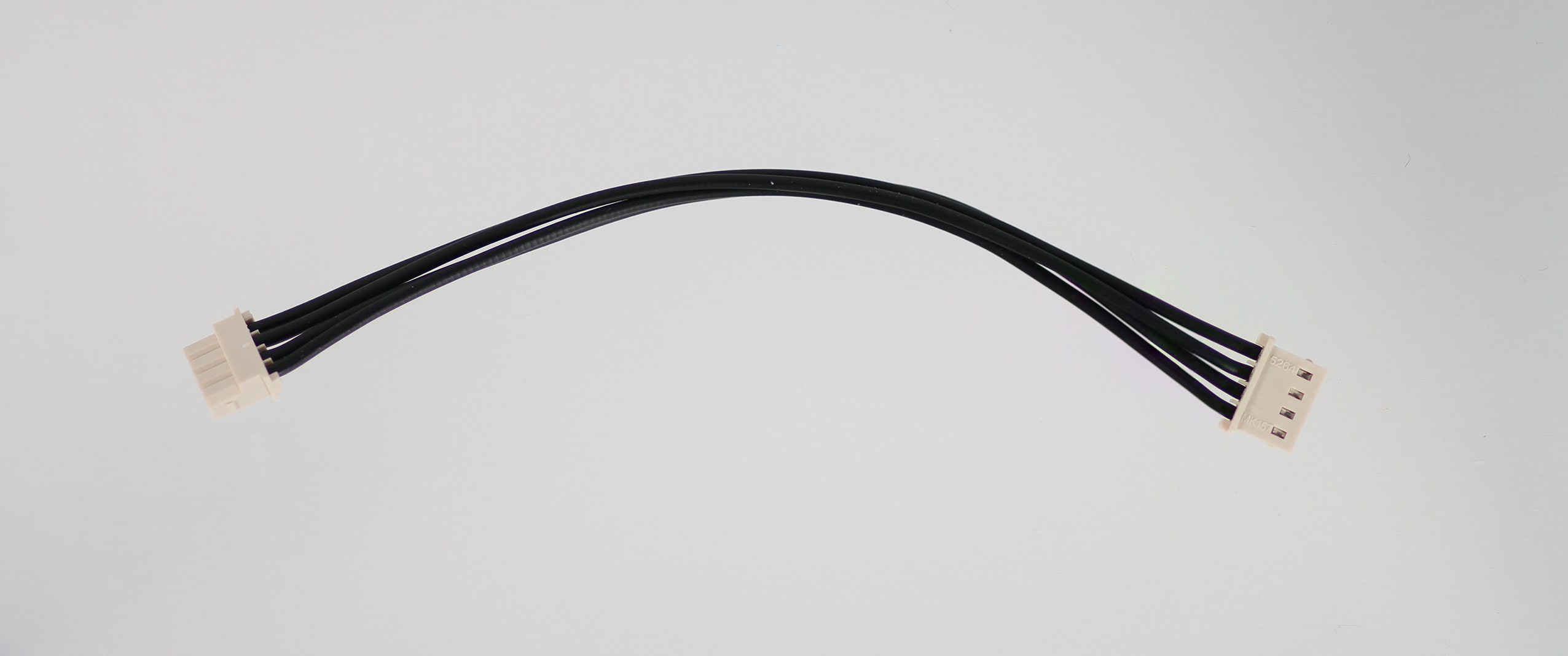
Description:
- VOXL Flight and VOXL to Power Module Cable
- Note there are three variants, -1, -3, and -4.
- “-1” is nominally for sale and part of our power module kits and larger drones, 125mm.
- MCBL-00001-1: VOXL Flight and VOXL/VOXL 2 to Power Module Cable
- “-3” and “-4” are shorter lengths (40mm and 70mm respectively) embedded in complete drone kits, but can be made available for purchase upon request
- MCBL-00001-3: VOXL Flight and VOXL/VOXL 2 to Power Module Cable, 40mm
- MCBL-00001-4: VOXL Flight and VOXL/VOXL 2 to Power Module Cable, 70mm
Where used:
- VOXL Flight J1013 to VOXL PM v2 or VOXL PM v3
- VOXL J10 to VOXL PM v2 or VOXL PM v3
- Included in several drone platforms, various lengths
Details:
| Component | Details |
|---|---|
| Connector A | Molex, 0050375043 |
| Connector B | Molex, 0050375043 |
| Length | 125mm (-1 variant), 40mm (-3 variant), 70mm (-4 variant) |
| Insulator | Silicon |
| Color | Black |
| Gauge | 20 AWG |
| Weight | 4.5 grams (-1 variant) |
Pinout: Note this cable is symmetric and can be used in either direction where the power module is the voltage source and the VOXL/VOXLFlight/VOXL 2 are the loads for pin 1.
| A | B | ||
|---|---|---|---|
| 1 | 5V DC | 1 | 5V DC |
| 2 | GND | 2 | GND |
| 3 | I2C3_SCL | 3 | PM_SCL |
| 4 | I2C3_SDA | 4 | PM_SDA |
Pinout, Part Number, & Additional Specs: See -1 Drawing Here, See -3 Drawing Here, and See -4 Drawing Here Contact ModalAI on the Forum for .DXF or .DWG formats of these drawings.
MCBL-00003
Description:
- Flight Core to Power Module Cable
Where Used:
Details:
| Component | Details |
|---|---|
| Connector A | JST, GHR-06V-S |
| Connector B | Molex, 0050375043 |
| Length | 120mm |
| Insulator | PVC (flexible) |
| Color | Black |
| Gauge | 26 AWG |
Pinout:
| A | B | ||
|---|---|---|---|
| 1 | 5V DC (Load) | 1 | 5V DC (Source) |
| 2 | - | - | |
| 3 | - | - | |
| 4 | EXP_I2C_SCL | 3 | PM_SCL |
| 5 | EXP_I2C_SDA | 4 | PM_SDA |
| 6 | GND | 2 | GND |
Pinout, Part Number, & Additional Specs: See Drawing Here Contact ModalAI on the Forum for .DXF or .DWG formats of these drawings.
MCBL-00004
Description:
- PWM Output Cable
Where Used:
- VOXL Flight J1007 or Flight Core J7 to PWM Break Out Board (MCCA-M0022)
Details:
| Component | Details |
|---|---|
| Connector A | JST, GHR-10V-S |
| Connector B | JST, GHR-10V-S |
| Length | 120mm |
| Insulator | PVC (flexible) |
| Color | Black |
| Gauge | 26 AWG |
Pinout: Note this cable is symmetric and can be used in either direction with the FlightCore side providing 5VDC voltage as the Source for reference/monitor circuits only (cannot power a servo/BLDC).
| A | B | ||
|---|---|---|---|
| 1 | 5V DC | 1 | 5V DC |
| 2 | PWM_CH0 | 2 | PWM_CH0 |
| 3 | PWM_CH1 | 3 | PWM_CH1 |
| 4 | PWM_CH2 | 4 | PWM_CH2 |
| 5 | PWM_CH3 | 5 | PWM_CH3 |
| 6 | PWM_CH4 | 6 | PWM_CH4 |
| 7 | PWM_CH5 | 7 | PWM_CH5 |
| 8 | PWM_CH6 | 8 | PWM_CH6 |
| 9 | PWM_CH7 | 9 | PWM_CH7 |
| 10 | GND | 10 | GND |
Pinout, Part Number, & Additional Specs: See Drawing Here Contact ModalAI on the Forum for .DXF or .DWG formats of these drawings.
MCBL-00005
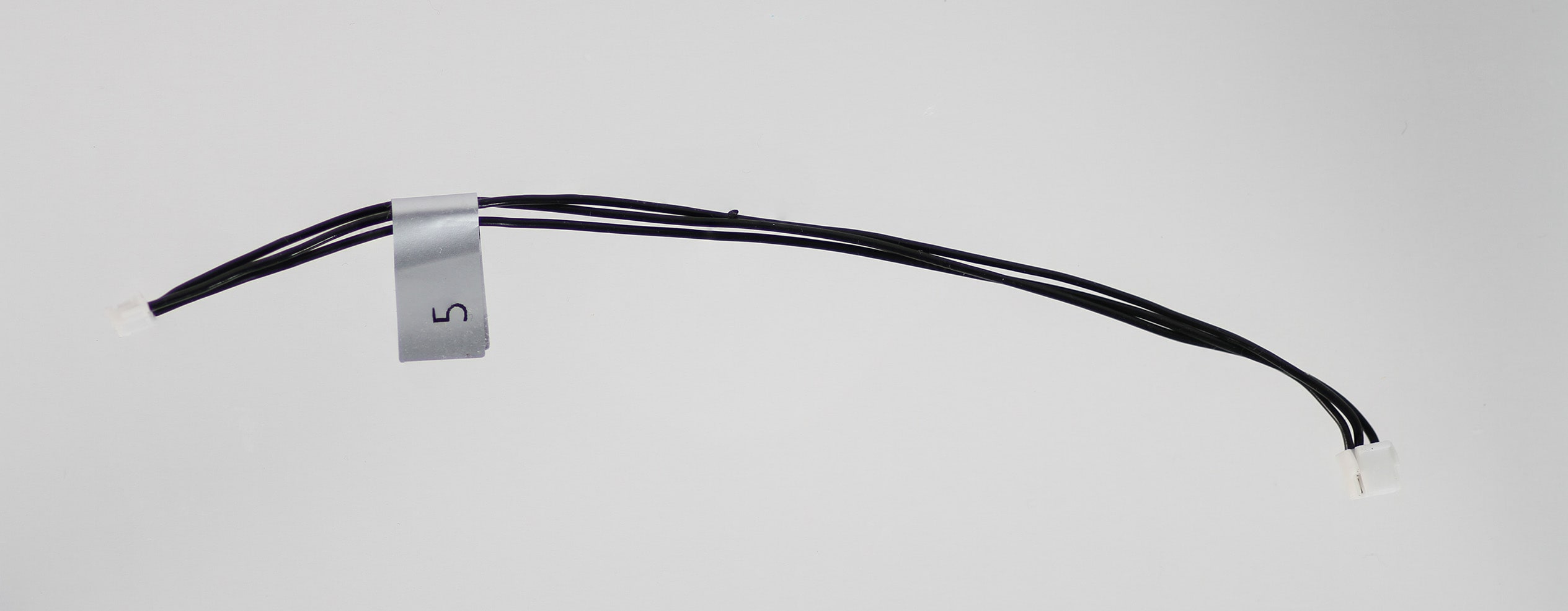
Description:
- RC Input Cable (Spektrum)
Where Used:
- VOXL Flight J1004 or Flight Core J12 to RC Receiver (e.g. Spektrum)
Details:
| Component | Details |
|---|---|
| Connector A | JST, GHR-04V-S |
| Connector B | JST, ZHR-3 |
| Length | 150mm |
| Insulator | PVC (flexible) |
| Color | Black |
| Gauge | 26 AWG |
Pinout:
| A | B | ||
|---|---|---|---|
| 1 | 3.3VDC (Source) | 1 | 3.3VDC (Load) |
| 2 | USART6_TX | - | NC |
| 3 | SPEKTRUM RX (3.3V), SBus RX (3.3V), USART6_RX | 3 | SPEKTRUM TX (3.3V), SBus TX (3.3V) |
| 4 | GND | 2 | GND |
Pinout, Part Number, & Additional Specs: See Drawing Here Contact ModalAI on the Forum for .DXF or .DWG formats of these drawings.
MCBL-00007
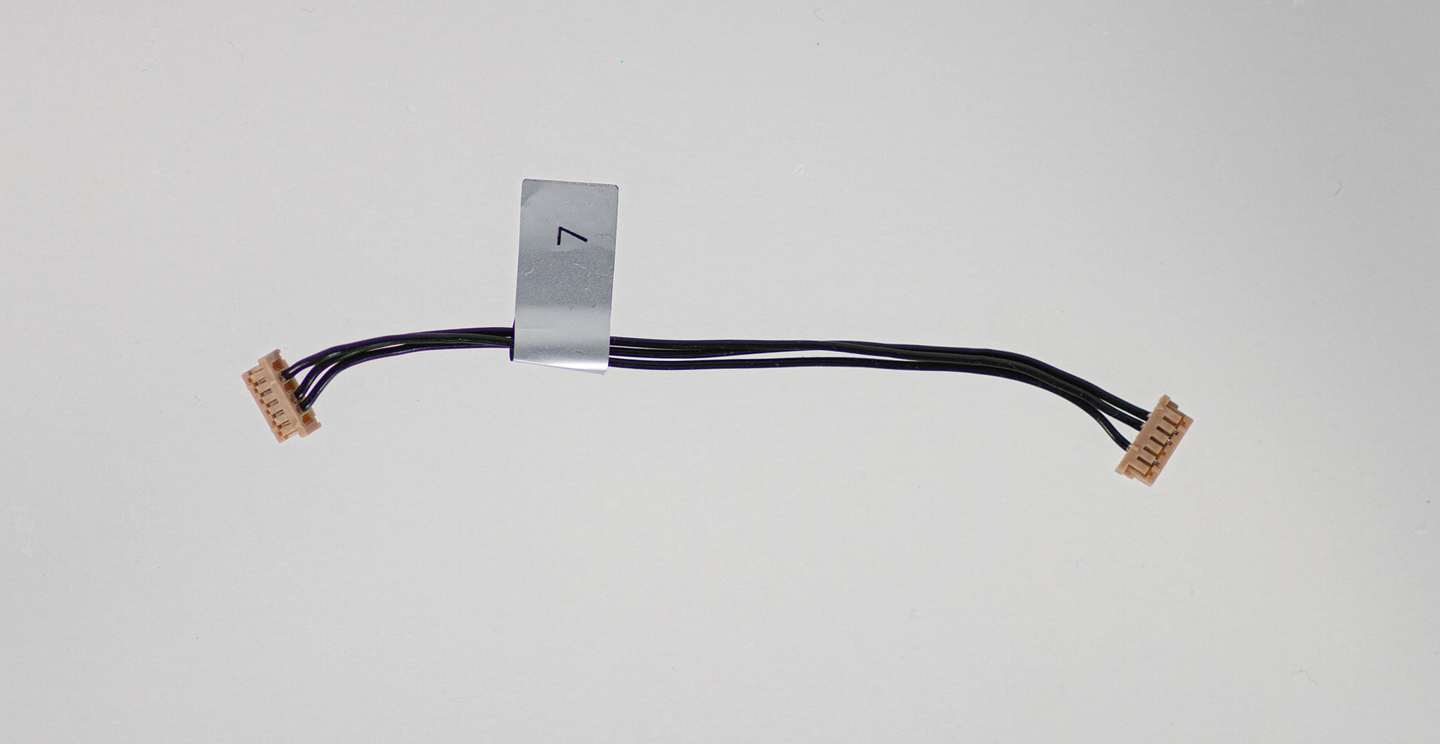
Description:
- VOXL to Flight Core Serial Cable (provides MAVLink connection over UART between VOXL and Flight Core)
- VOXL to VOXL ESC Cable (straight through)
- No Power Connection, Signals + GND connections only
Where Used:
- Flight Core J1 to VOXL J12
- VOXL J12 to VOXL ESC (J2 on VOXL ESC V2/V3, M0027/M0049/M0117/M0134)
Details:
| Component | Details |
|---|---|
| Connector A | DF13-6S-1.25C (Flight Core) |
| Connector B | DF13-6S-1.25C (VOXL) |
| Length | 90mm |
| Insulator | PVC (flexible) |
| Color | Black |
| Gauge | 26 AWG |
Pinout:
| A | B | ||
|---|---|---|---|
| 1 | - | 1 | |
| 2 | FC RX | 2 | VOXL TX |
| 3 | FC TX | 3 | VOXL RX |
| 4 | - | 4 | - |
| 5 | GND | 5 | GND |
| 6 | - | 6 | - |
Pinout, Part Number, & Additional Specs: See Drawing Here Contact ModalAI on the Forum for .DXF or .DWG formats of these drawings.
MCBL-00008
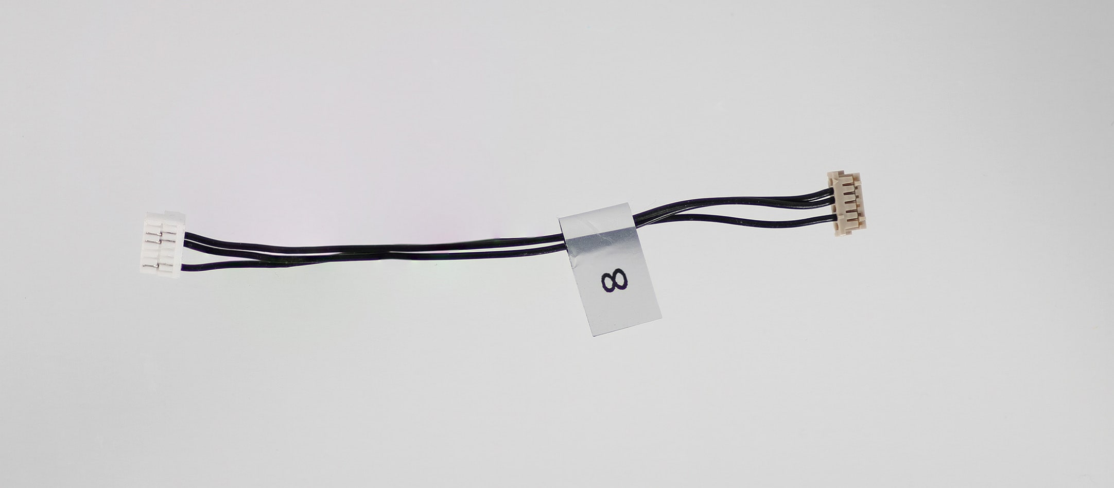
Description:
- VOXL to Flight Controller TELEM port (Dronecode Compliant)
- No Power Connection, Signals + GND connections only
Where Used:
- VOXL J12 to Flight Controller TELEM, such as Flight Core J5 or other Dronecode Compliant TELEM ports
Details:
| Component | Details |
|---|---|
| Connector A | DF13-6S-1.25C (VOXL) |
| Connector B | JST, GHR-06V-S (Flight Core) |
| Length | 90mm |
| Insulator | PVC (flexible) |
| Color | Black |
| Gauge | 26 AWG |
Pinout:
| A | B | ||
|---|---|---|---|
| 1 | - | - | |
| 2 | VOXL TX | 3 | FC RX |
| 3 | VOXL RX | 2 | FC TX |
| 4 | - | - | - |
| 5 | GND | 6 | GND |
| 6 | - | - |
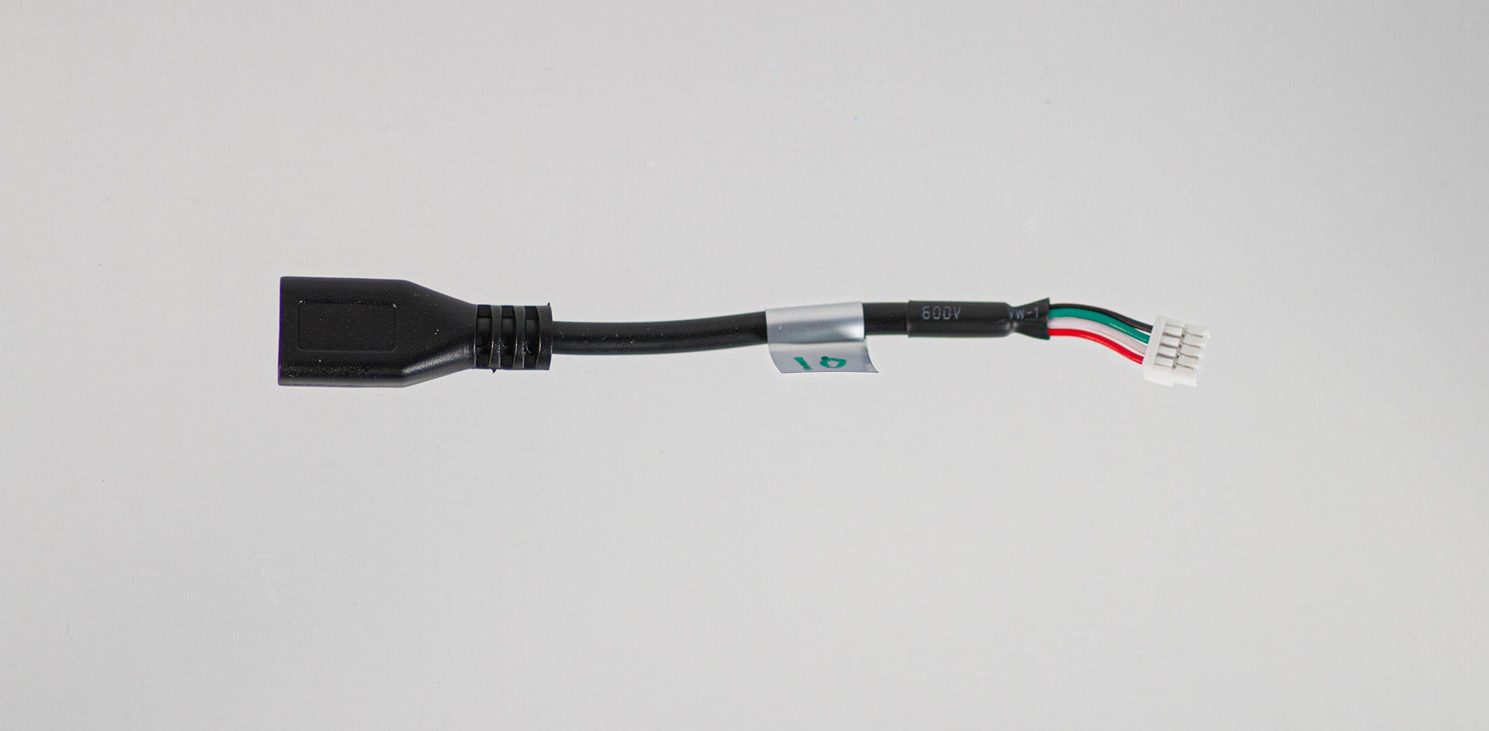
MCBL-00009
Description:
- 4-pin JST to USBA Female/Receptacle Cable
Where Used:
- Used for connecting ModalAI USB Hosts (JST side, examples below) to USB Peripherals (Type A side)
- LTE Modem and USB Hub Addon J16 and J17 to USB peripheral device
- USB Expander and Debug Board to USB peripheral device
- Microhard and USB Hub Add-on USB J16 and J17 to USB peripheral device
Details:
| Component | Details |
|---|---|
| Connector A | JST, GHR-04V-S) |
| Connector B | USB 2.0 Type A Female/Receptacle |
| Length | ~60mm |
Pinout:
| A | B | ||
|---|---|---|---|
| 1 | VBUS (Source side) | 1 | VBUS (Load side) |
| 2 | DATA_M | 2 | D- |
| 3 | DATA_P | 3 | D+ |
| 4 | GND | 4 | GND |
Pinout, Part Number, & Additional Specs: See Drawing Here Contact ModalAI on the Forum for .DXF or .DWG formats of these drawings.
MCBL-00010
Description:
- 4-pin JST to micro USB Female/Receptacle Cable
- Used for connecting USB Hosts such as a PC (Micro USB connector side) to ModalAI USB Peripherals (JST side).
- Note: Micro USB side requires a standard Type-A to MicroUSB cable/adapter depending on your system setups
- Flight Core (PX4) to micro USB cable to QGroundControl (MAVLink)
- Microhard Standalone Modem to micro USB cable to host computer
- Used for connecting USB Hosts such as a PC (Micro USB connector side) to ModalAI USB Peripherals (JST side).
Where Used:
- VOXL Flight J1006 or Flight Core J3 to micro USB cable to Host Computer with QGroundControl
- Microhard USB Carrier Board USB2 Host port to micro USB cable to Host Computer
Details:
| Component | Details |
|---|---|
| Connector A | JST, GHR-04V-S |
| Connector B | Micro USB 2.0 Female |
| Length | ~60mm |
Pinout:
| A | B | ||
|---|---|---|---|
| 1 | VBUS (Load) | 1 | VBUS (Source) |
| 2 | DATA_M | 2 | D- |
| 3 | DATA_P | 3 | D+ |
| - | 4 | ID (unused) | |
| 4 | GND | 5 | GND |
Pinout, Part Number, & Additional Specs: See Drawing Here Contact ModalAI on the Forum for .DXF or .DWG formats of these drawings.
MCBL-00011-1
Description:
- VOXL-PM-Y for Flight Deck R0/R1 Cable
- Powers both VOXL and FlightCore from one Power Module, with the I2C bus for power monitoring going to FlightCore
Where Used:
- VOXL-m500-R1
- VOXL J1 + Flight Core J6to VOXL PM v2 or VOXL PM v3
Details:
| Component | Details |
|---|---|
| Connector A | JST, GHR-06V-S (Flight Core side, 4 wires) |
| Connector B | Molex, 0050375043 (Power Module side, 4 wires) |
| Connector C | Molex, 0050375043 (VOXL side, 2 wires) |
| Length | 120mm |
| Insulator | PVC (flexible) |
| Color | Black |
| Gauge | 22AWG (B-to-C)/ 26AWG (B-to-A) |
Pinout:
| C | VOXL | B | VOXL PM | A | Flight Core |
|---|---|---|---|---|---|
| 1 | 5V DC (Load) | 1 | 5V DC (Source) | 1 | 5V DC (Load) |
| 2 | GND | 2 | GND | 6 | GND |
| - | 3 | SCL | 4 | EXP_I2C_SCL | |
| - | 4 | SDA | 5 | EXP_I2C_SDA |
MCBL-00013
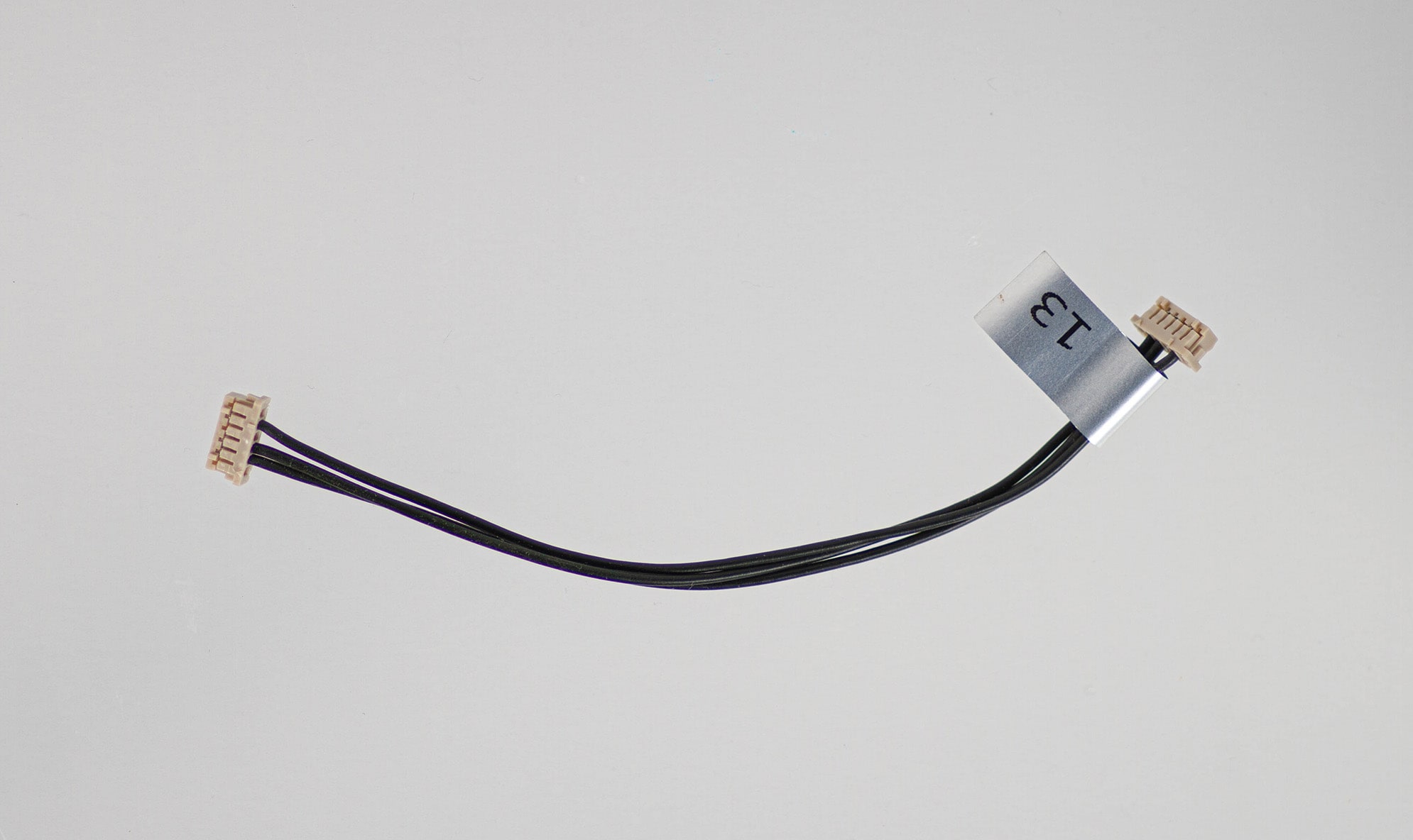
Description:
- VOXL Flight to VOXL ESC V2/V3 Cable (cross over)
- This is a UART RX/TX cross-over version of MCBL-00007 for Hirose DF13-6P
- No Power Connection, Signals + GND connections only
Where Used:
- VOXL Flight J1002 to VOXL ESC (J2 on VOXL ESC V2/V3, M0027/M0049/M0117/M0134)
Details:
| Component | Details |
|---|---|
| Connector A | DF13-6S-1.25C (VOXL Flight) |
| Connector B | DF13-6S-1.25C (ESC) |
| Length | 100mm |
| Insulator | PVC (flexible) |
| Color | Black |
| Gauge | 26 AWG |
Pinout:
| A | VOXL Flight | B | VOXL ESC V2/V3 |
|---|---|---|---|
| 1 | - | - | |
| 2 | RX | 3 | TX |
| 3 | TX | 2 | RX |
| 4 | - | - | - |
| 5 | GND | 5 | GND |
| 6 | - | - | - |
MCBL-00014
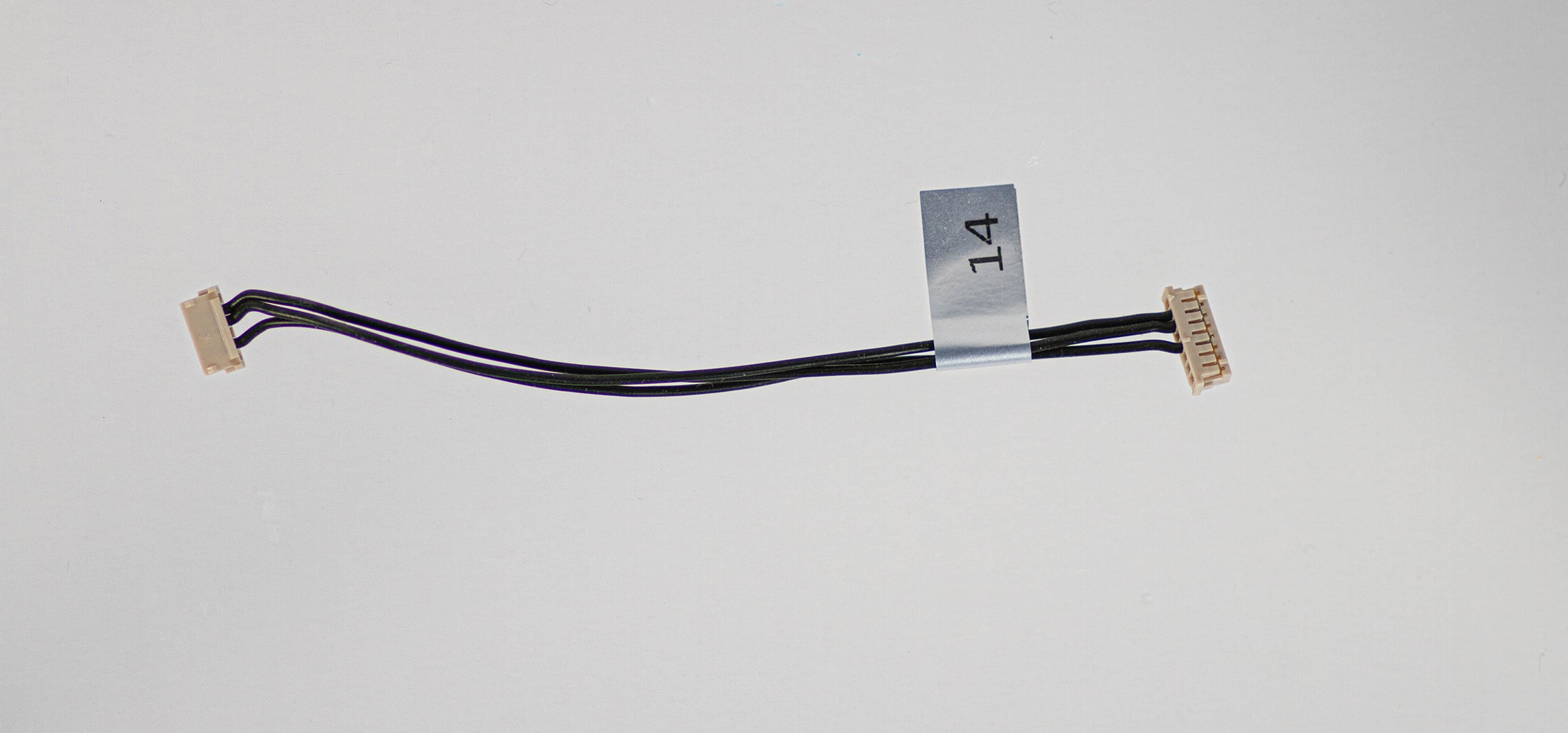
Description:
- Flight Core to VOXL ESC Cable (cross over)
- This is just like MCBL-00013 but one of the 6-pin DF13’s is replaced by an 8-pin for FlightCore J4
- No Power Connection, Signals + GND connections only
Where Used:
- Flight Core J4 to VOXL ESC (J2 on VOXL ESC V2/V3, M0027/M0049/M0117/M0134)
- Connecting ESC’s’ to VOXL CAM Flight Core (on Seeker Drone, for example)
Details:
| Component | Details |
|---|---|
| Connector A | DF13-8S-1.25C (Flight Core) |
| Connector B | DF13-6S-1.25C (ESC) |
| Length | 100mm |
| Insulator | PVC (flexible) |
| Color | Black |
| Gauge | 26 AWG |
Pinout:
| A | Flight Core | B | VOXL ESC V2/V3 |
|---|---|---|---|
| 1 | - | - | |
| 2 | RX | 3 | TX |
| 3 | TX | 2 | RX |
| 4 | - | - | - |
| 5 | GND | 5 | GND |
| 6 | - | - | - |
| 7 | - | ||
| 8 | - |
MCBL-00015
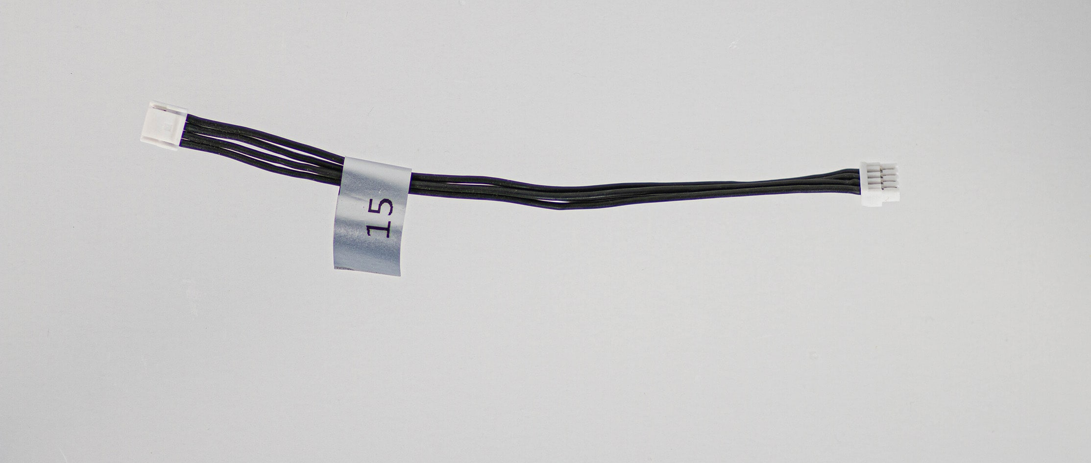
Description:
- 4pin-JST-to-4pin-JST cable (straight through 1:1)
Where Used:
- VOXL USB Add-On boards to Stand Alone Modem Boards, ESC UART from VOXL 2 to Mini-ESC (M0129)
- Conforms to all ModalAI 4-pin JST USB2.0 formats, either Host (VBUS, Pin1, is a source) or Peripheral (VBUS, Pin1, is a load)
- Great item to have for making your own cables!!
- Note there are four variants, -1, -2, -3, and -4.
- “-1” is nominally for sale, 100mm.
- “-2” is a longer length, 150mm, embedded in complete drone kits, but can be made available for purchase upon request
- “-3” is a shorter length, 50mm, embedded in Starling drone kits, but can be made available for purchase upon request
- “-4” is the shortest length at 15mm and can be made available for purchase upon request.
- Note the -4 variant has no label on it due to its size.
Details:
| Component | Details |
|---|---|
| Connector A | JST, GHR-04V-S |
| Connector B | JST, GHR-04V-S |
| Length | 100mm (-1 variant), 150mm (-2 variant), 50mm (-3 variant), 15mm (-4 variant) |
| Insulator | PVC (flexible) |
| Color | Black |
| Gauge | 26 AWG |
| Weight | 1.1 grams (-1 variant), 1.4 grams (-2 variant), 0.7 grams (-3 variant), 0.4 grams (-4 variant) |
Pinout:
| A | B | ||
|---|---|---|---|
| 1 | Pin1 | 1 | Pin1 |
| 2 | Pin2 | 2 | Pin2 |
| 3 | Pin3 | 3 | Pin3 |
| 4 | Pin4 | 4 | Pin4 |
Pinout, Part Number, & Additional Specs: See -1 Drawing Here, See -2 Drawing Here, See -3 Drawing Here, See -4 Drawing Here Contact ModalAI on the Forum for .DXF or .DWG formats of these drawings.
MCBL-00016
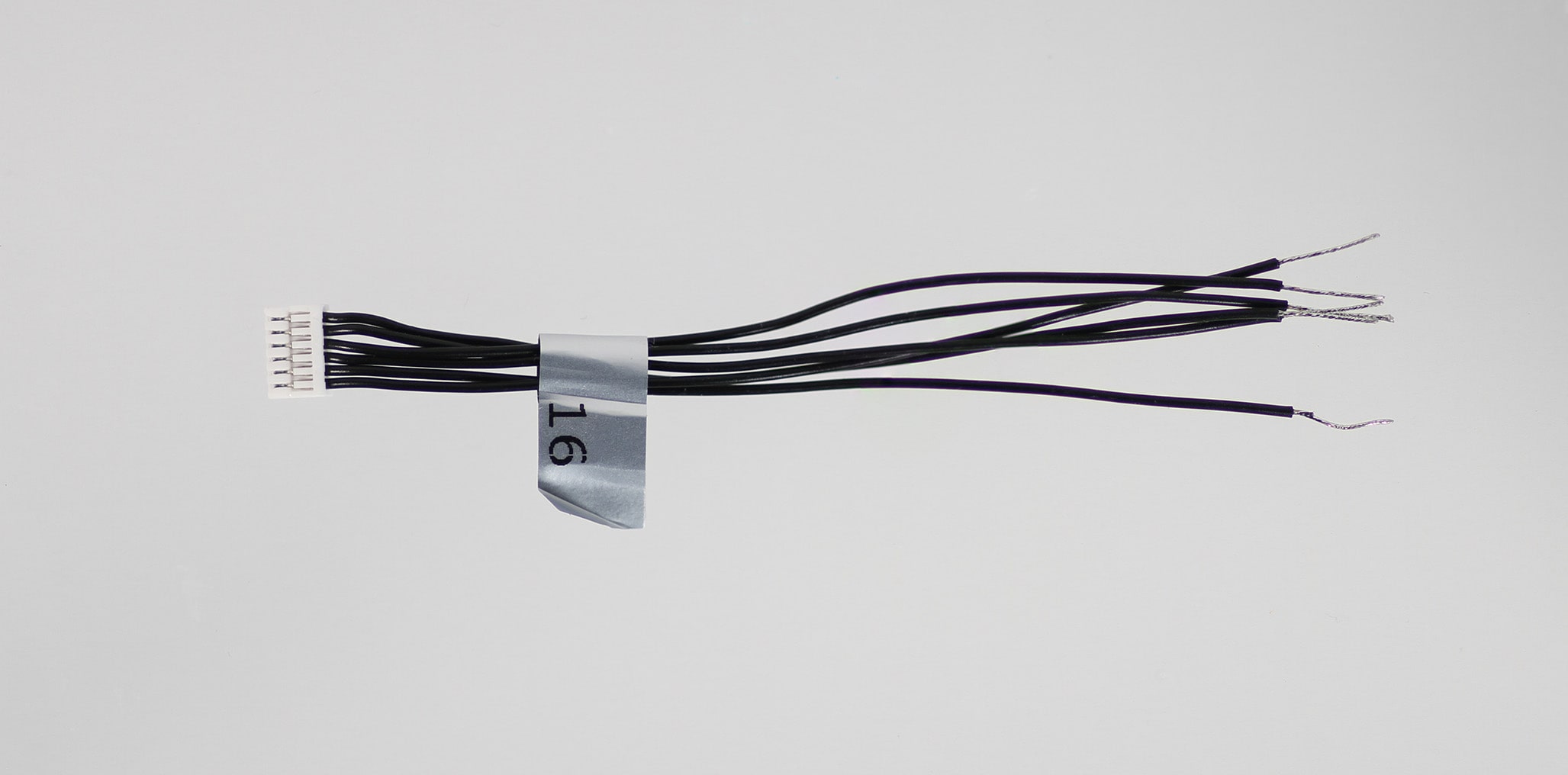
Description:
- 6pin-JST-to-pigtail break out cable
Where Used:
- M0048 ICM42688 IMU Breakout Board
- Any ModalAI 6-pin JST where soldering or custom harnesses are needed
- Note: pigtail side is tinned for ~10mm making it easy to install JST SSHL-002T-P0.2 pins if needed
- Great item to have for making your own cables!!
Details:
| Component | Details |
|---|---|
| Connector A | JST, GHR-06V-S) |
| Connector B | None |
| Length | 100mm |
| Insulator | PVC (flexible) |
| Color | Black |
| Gauge | 26 AWG |
| Weight | 1.4 grams |
Pinout:
| A | |||
|---|---|---|---|
| 1 | 1 | (pigtail) | |
| 2 | 2 | (pigtail) | |
| 3 | 3 | (pigtail) | |
| 4 | 4 | (pigtail) | |
| 5 | 5 | (pigtail) | |
| 6 | 6 | (pigtail) |
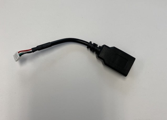
MCBL-00017
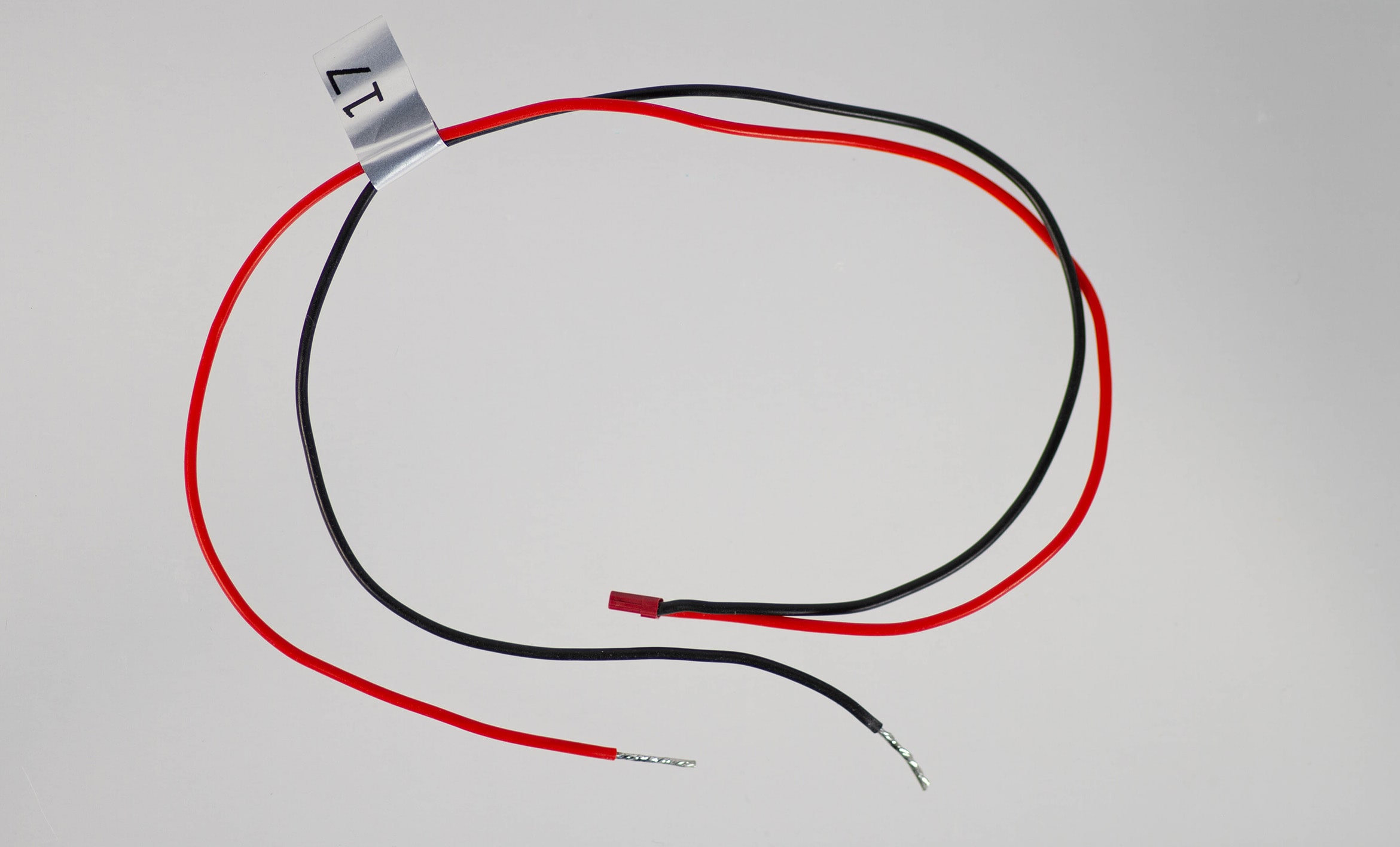
Description:
- Power Supply (not supplied) to Stand Alone Modem Dongle
- Connector mates to the Red JST J8 on Microhard boards, or J3 on Sierra LTE V2 modem boards
- Tinned leads on the other side allow soldering or converting to pins as needed by the customer.
- NOTE: Cut the wire length to 150mm or less if anticipating needing the full 4A capable of these designs (high power radio modes + all USB connectors used). Refer to the Where Used links below for power consumption estimates.
Where Used:
Details:
| Component | Details |
|---|---|
| Connector A | SFHR-02V-R |
| Connector B | None/Tinned ~10mm |
| Length | 300 mm |
| Insulator | PVC (flexible) |
| Color | Red/Black |
| Gauge | 22 AWG |
| Pre-crimped | ALEALEA22K102 |
Pinout:
| A | Wire | B | Modem |
|---|---|---|---|
| 1 | RED (Source) | 1 | VDCIN_5V (Load) |
| 2 | BLACK | 2 | GND |
MCBL-00018
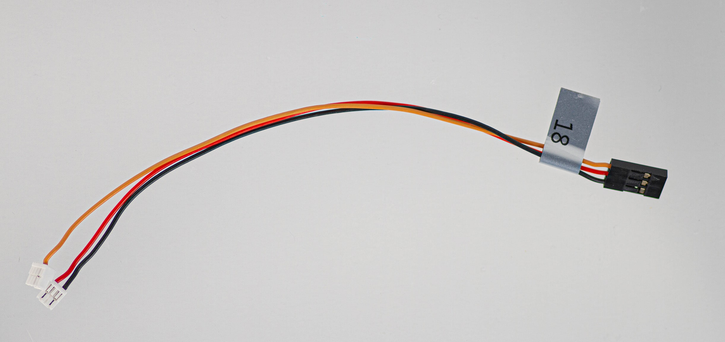
Description:
- RC Input (S.Bus, FrSky)
- Picks up Power on Red+Black, and Receive Signal on Orange from FlightCore or VOXLFlight to a R/C receiver 3-pin 0.1” hobby format
- ModalAI conforms to the notion of Pin 1 = Signal, Pin 2 = 5V, & Pin 3 = GND for the 3-pin hobby format. Please notify us if you see anything here to the contrary.
- Note: This is only intended for remote receivers and cannot power high current servos or BLDCs
Where Used:
- 4-pin JST (connector B): VOXL Flight J1004 or Flight Core J12 and 3-pin JST (connector A): VOXL Flight J1003 or Flight Core J9 to 3-pin Harwin M20 Receptacle (connector C) to RC Receiver (e.g. S.Bus/FrSky)
- Note: This is not for Spektrum, which requires +3.3V. For Spektrum, please see MCBL-00005
| Component | Details |
|---|---|
| Connector A | JST GHR-03V-S, for +5V Power/GND |
| Connector B | JST GHR-04V-S, for UART_RX signal, +3.3V levels |
| Connector C | Harwin M20-1060300, CONN RCPT HSG 3POS 2.54mm (or similar) |
| Length | 150 mm |
| Insulator | PVC (flexible) |
| Color | Red/Black/Orange |
| Gauge | 26 AWG |
Pinout:
| A | Power | C | RC Receiver | B | Signal |
|---|---|---|---|---|---|
| 1 | RED (5V, Source) | 2 | 5V DC (Load) | ||
| 2 | 1 | S.Bus/DSMX (Orange) | 3 | S.Bus/DSMX (Orange) | |
| 3 | BLACK (GND) | 3 | GND | ||
MCBL-00020
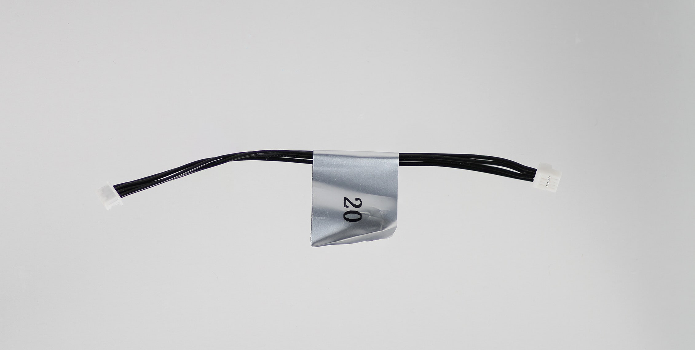
Description:
- USB Cable, Arducam-4 pin Molex Picoblade to 4 -pin JST-GH
Where Used:
- VOXL Add-ons with USB hub to ArduCam USB Camera
Details:
| Component | Details |
|---|---|
| Connector A | 4POS 1.25mm PICOBLADE |
| Connector B | 4POS 1.25mm JST |
| Length | 100mm |
| Insulator | Silicon |
| Color | Black |
| Gauge | 26 AWG |
Pinout:
| A | B | ||
|---|---|---|---|
| 1 | V_BUS | 1 | V_BUS |
| 2 | DATA_M | 2 | DATA_M |
| 3 | DATA_P | 3 | DATA_P |
| 4 | GND | 4 | GND |
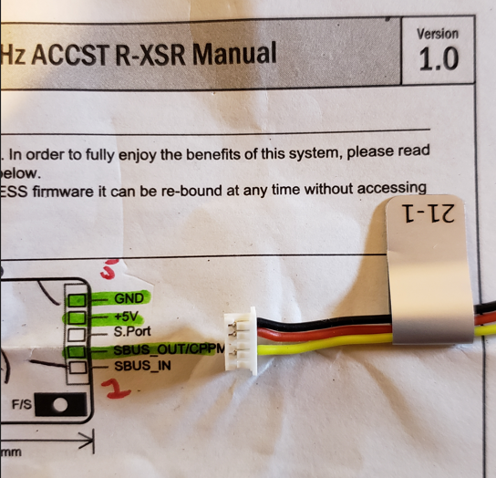
MCBL-00021
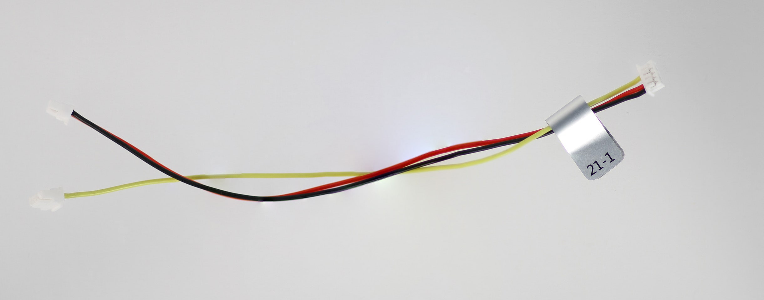
Description:
- RC Input (FrSky R-XSR)
- Picks up Power on Red+Black, and Receive Signal on Yellow from FlightCore or VOXLFlight to FrSky R-XSR format R/C receiver 5-pin Picoblade format
- Note: This is just like MCBL-00018 but instead of the 3-pin hobby format receptacle, it is pinned for the FrSky R-XSR 5-position Picoblade
Where Used:
- 4-pin JST (connector B): VOXL Flight J1004 or Flight Core J12 and 3-pin JST (connector A): VOXL Flight J1003 or Flight Core J9 to 5-pin Molex Picoblade (connector C) to FrSky R-XSR Receiver
| Component | Details |
|---|---|
| Connector A | JST GHR-03V-S, for +5V Power/GND |
| Connector B | JST GHR-04V-S, for UART_RX signal, +3.3V levels |
| Connector C | Molex 0510210500, 5-position Picoblade housing 1.25mm |
| Length | 140 mm |
| Insulator | PVC (flexible) |
| Color | Red/Black/Yellow |
| Gauge | 26 AWG |
Pinout:
| A | Power | C | RC Receiver | B | Signal |
|---|---|---|---|---|---|
| 1 | RED (5V, Source) | 4 | 5V DC (Load) | ||
| 2 | 2 | S.Bus (Yellow) | 3 | S.Bus (Yellow) | |
| 3 | BLACK (GND) | 5 | GND | ||
Pinout, Part Number, & Additional Specs: See Drawing Here Contact ModalAI on the Forum for .DXF or .DWG formats of this drawing.
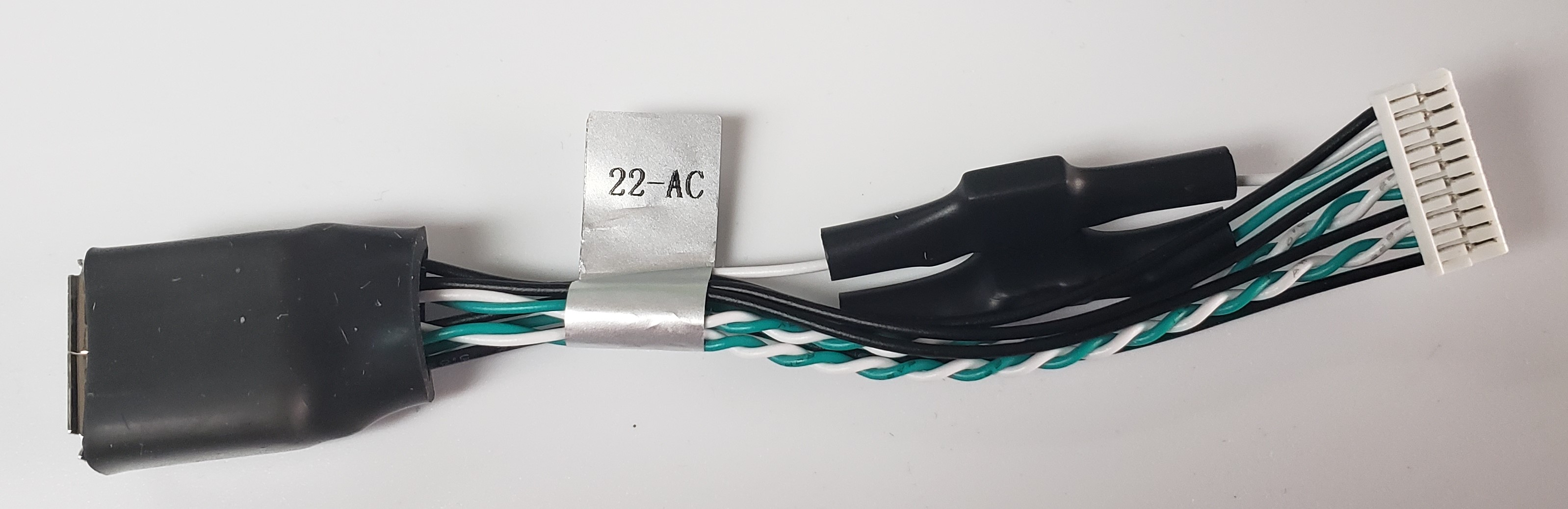
MCBL-00022
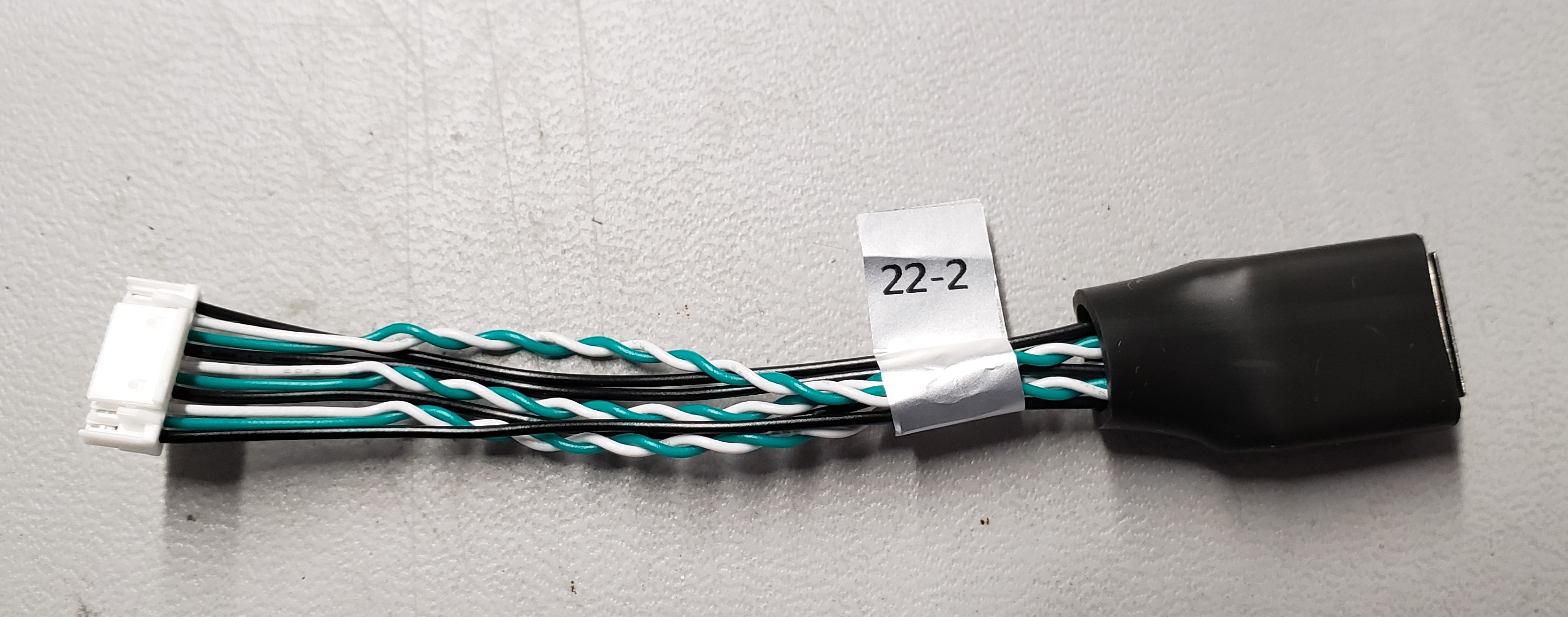
Description:
- USB3 10-pin JST cable to USB3-Type A Receptacle
- Note: This is not qualified for 10Gbps speeds. This is a proto-type design suitable for most application development. Customers are advised to source their own shielded and speed-qualified cable for high-volume needs.
- Custom “AC” variant for VOXL 2 Mini Use Case, as described Here
- Make sure the part number you order includes a “-ac” in the ModalAI part number. Due to the complexity, this is more costly than our standard cable.
- Make sure the part number you order includes a “-ac” in the ModalAI part number. Due to the complexity, this is more costly than our standard cable.
Where Used:
- Any ModalAI CCA USB downstream port (host only) with the 10-pin JST ModalAI USB3 format (examples are M0062, M0067, M0090, M0104, M0130).
- VOXL 2 Mini must specifically use MCBL-00022-AC if USB3 speeds are required. If USB2 speeds are sufficient, the nominal MCBL-00022-2 is suggested for the lower cost.
Details:
| Component | Details |
|---|---|
| Connector A | 10POS 1.25mm JST, GHR-10V-S |
| Connector B | CONN RCPT USB3.0 TYPEA, CNC Tech 1003-006-01200 |
| Length | 80mm |
| Insulator | Silicon |
| Color | Black, White/Green TP |
| Gauge | 26AWG VBUS/GND, 28AWG Twisted Pair Signals (the MCBL-00022-AC inherently looses some of the Twists) |
Pinout, Part Number, & Additional Specs: See Drawing Here Contact ModalAI on the Forum for .DXF or .DWG formats of this drawing.
MCBL-00024

Description:
- Power Module to Stand Alone Modem Cable
Where Used:
- Used to power a standalone modem board (Sierra M0030-2/M0130-2, or Microhard M0048-2/M0059-2, or 5G M0090-2) directly from the ModalAI Power Module V3
Details:
| Component | Details |
|---|---|
| Connector A | Molex, 0050375043 (Power Module side, 2 wires) |
| Connector B | SFHR-02V-R (Modem side, 2 wires) |
| Length | 100mm |
| Insulator | PVC (flexible) |
| Color | Black/Red |
| Gauge | 26AWG |
Pinout:
| A | POWER MODULE | B | Modem Side |
|---|---|---|---|
| 1 | 5V DC (Source) | 1 | 5V DC (Load) |
| 2 | GND | 2 | GND |
| 3 | - | ||
| 4 | - |
MCBL-00025
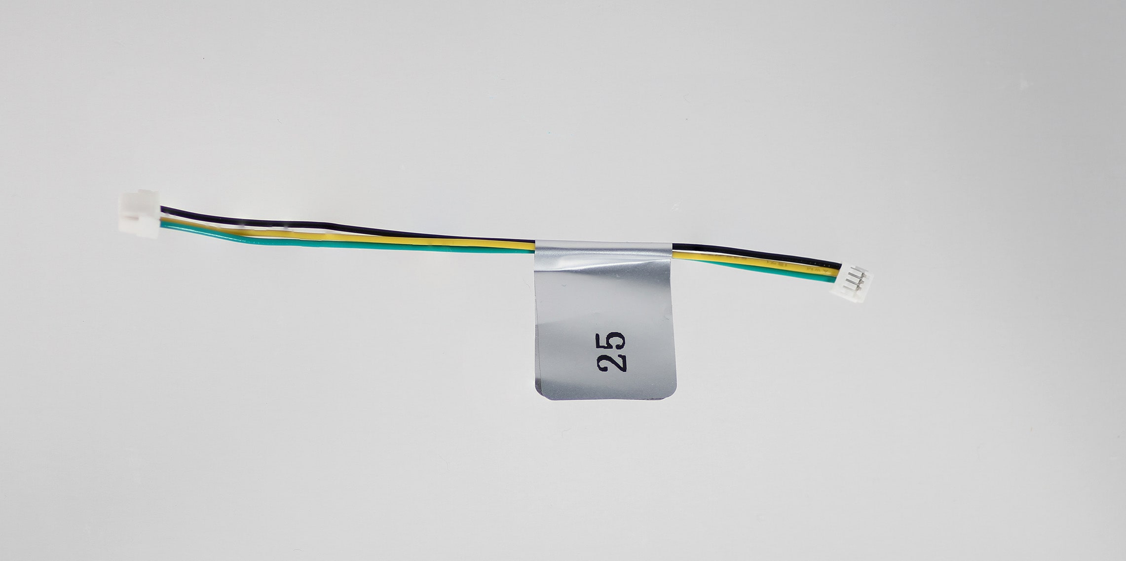
Description:
- LTE v2 to Flight Core (DroneCode Compliant) Telemetry
- No Power Connection, Signals + GND connections only
Where Used:
- The M0030 Sierra 4G/LTE Modem has a spare UART port on J9 (matches the pinout of J2 as shown here)
- This connector provides a 3.3V UART link directly to the Modem, which can be connected to FlightCore J5 (UART7) to create a 4G Telemetry or general purpose data link.
- Note: Software support of this feature may still be in BETA form, please contact ModalAI for support
- Flightcore side pinouts also match other DroneCode compliant connectors J6 (expansion UART4) and J10 (GNSS UART1) ports
- The 4-pin side on the 4G LTE Modem also matches many other Serial Debug Ports on ModalAI HW and can be used as a general purpose UART converter from the 4-wire eSH format to 6-wire eGH format (DroneCode Compliant)
Details:
| Component | Details |
|---|---|
| Connector A | JST 1.25mm GHR-06V-S, FlightCore Side, +3.3V levels |
| Connector B | JST 1.0mm SHR-06V-S, 4G Modem Side, +3.3V levels |
| Length | 100mm |
| Insulator | Silicon |
| Color | black |
| Gauge | 26 AWG |
Pinout:
| A | B | ||
|---|---|---|---|
| 1 | - | 1 | - |
| 2 | TX (FlightCore Output/Transmit) | 2 | RX (Modem Input/Receive) |
| 3 | RX (FlightCore Input/Receive) | 3 | TX (Modem Output/Transmit) |
| 4 | - | 4 | GND |
| 5 | - | - | - |
| 6 | GND | - | - |
MCBL-00028
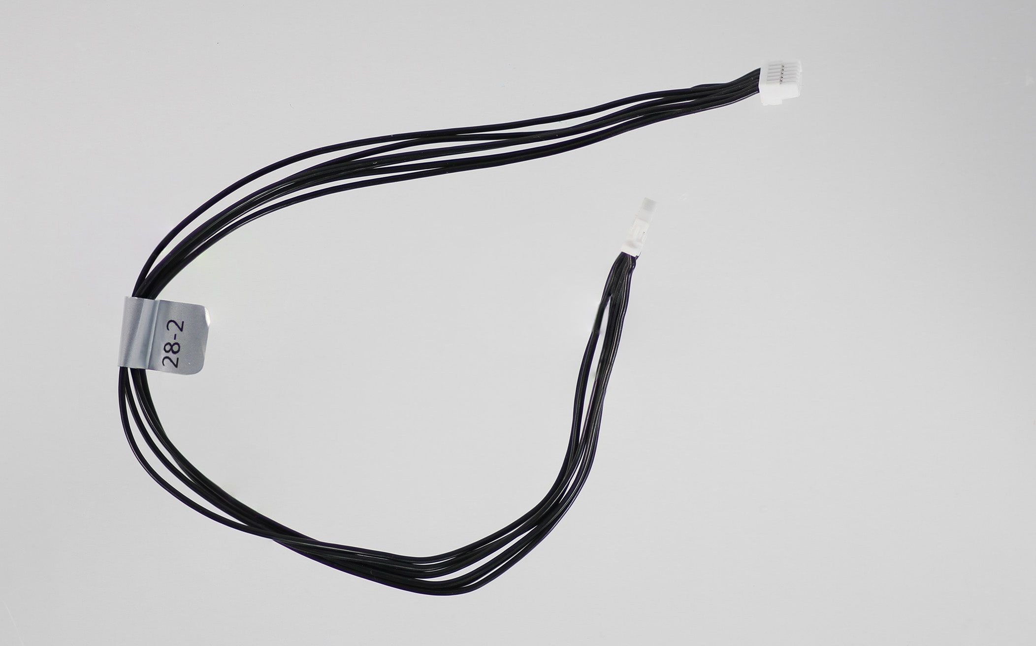
Description:
- Seeker GPS Cable
Where Used:
- Connects HolyBro GPS/Magnetometer unit to VOXL-CAM on Seeker drone using FlightCore J10 (6-pin)
- This cable provides power + UART + I2C
Details:
| Component | Details |
|---|---|
| Connector A | 10 POS 1.0mm JST, GNSS Side |
| Connector B | 6 POS 1.25mm JST, FlightCore J10 side |
| Length | 230mm |
| Insulator | Silicon |
| Color | Black |
| Gauge | 26 AWG |
Pinout:
| A | B | ||
|---|---|---|---|
| 1 | 5VDC (Load) | 1 | 5VDC (Source) |
| 2 | RX (GNSS Input) | 2 | TX (FlightCore Output) |
| 3 | TX (GNSS Output) | 3 | RX (FlightCore Input) |
| 4 | SCL | 4 | SCL (FlightCore Host Side) |
| 5 | SDA | 5 | SDA (FlightCore Host Side) |
| 6 | - | - | - |
| 7 | - | - | - |
| 8 | - | - | - |
| 9 | - | - | - |
| 10 | GND | 6 | GND |
MCBL-00029
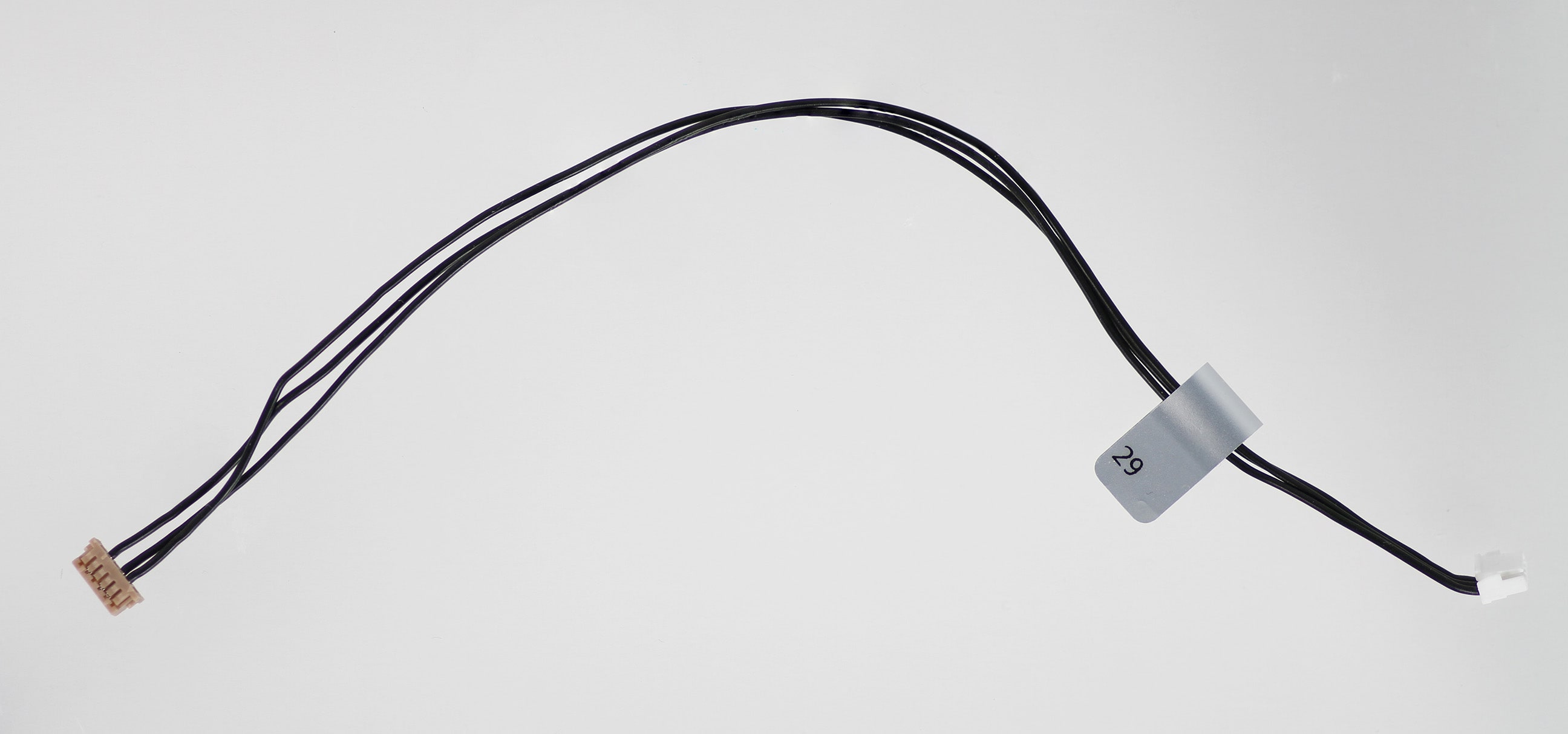
Description:
- RB5 Flight (M0052) or VOXL 2 (M0054) to VOXL ESC V2/V3 Cable
- This is just like MCBL-00007 but one side is now the new 4-pin JST GH format for ESC instead of DF13 on VOXL
- No Power Connection, Signals + GND connections only
- Note there are two variants, -1, and -2.
- “-1” is nominally for sale and part of our larger drones at 200mm.
- “-2” is shorter at 70mm and will be embedded into the new Starling drone kit, but can be made available for purchase upon request
Where Used:
- Qualcomm Flight RB5 Mainboard ESC Port (J18) to VOXL ESC V2/V3 J2 (M0027/M0049/M0117/M0134)
- VOXL 2 ESC Port (J18) to VOXL ESC V2/V3 J2 (M0027/M0049/M0117/M0134)
- 200mm length for long wire M500 frame installations
- 70mm for smaller drone installations
Details:
| Component | Details |
|---|---|
| Connector A | DF13-6S-1.25C (VOXL ESC), +3.3V levels |
| Connector B | JST 1.25mm GHR-04V-S, RB5 Flight/VOXL 2 Side, +3.3V levels |
| Length | 200mm (-1 variant), 70mm (-2 variant) |
| Insulator | Silicon (flexible) |
| Color | Black |
| Gauge | 26 AWG |
Pinout:
| A | VOXL ESC V2/V3 | B | RB5 Flight / VOXL 2 |
|---|---|---|---|
| 1 | - | 1 | |
| 2 | ESC RX | 2 | VOXL 2/RB5-Flight TX |
| 3 | ESC TX | 3 | VOXL 2/RB5-Flight RX |
| 4 | - | - | - |
| 5 | GND | 4 | GND |
| 6 | - | - | - |
Pinout, Part Number, & Additional Specs: See -1 Drawing Here, See -2 Drawing Here Contact ModalAI on the Forum for .DXF or .DWG formats of these drawings.
MCBL-00030
Description:
- End-Of-Life: Being Replaced by MCBL-00040-2 with 3.5mm bullet terminal system
- 2mm Bullet Connector to tinned lead for ESC soldering and easy motor mating
- RB5 Flight ESC to motor cables (legacy usage)
- Note: We have various lengths for this cable
- MCBL-00030-2 = 250mm (as per drawing link below, but Obsolete, use other lengths),
- MCBL-00030-3 = 265mm
- MCBL-00030-4 = 210mm
Details:
| Component | Details |
|---|---|
| Connector A | Female Bullet Wire,2mm, 18-22AWG |
| Length | 250mm |
| Insulator | Silicon |
| Gauge | 20 AWG |
MCBL-00031
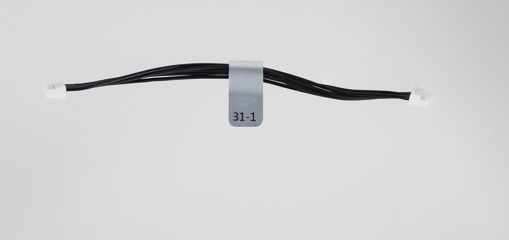
Description:
- 6 pin-JST-GH-to 6-pin-JST-GH passthrough (1:1/Straight-through wiring)
- Note there are two variants, -1, and -2.
- -1, 100mm, is nominally for sale and the -2 is a longer version at 150mm.
Where Used:
- Connects Qualcomm Flight RB5 Flight Deck Modem and Chirp Sensors
- Connects VOXL 2/VOXL 2 Mini and FlightCoreV2 Dronecode Compliant ports to Dronecode Compliant GNSS modules
- Chirp Breakout to Debug or Modem Carrier Board
- Any place where a 6-pin JST GH is used for debugging, external sensors, etc.
- Great item to have for making your own cables!!
Details:
| Component | Details |
|---|---|
| Connector A | 6POS 1.25mm JST |
| Connector B | 6POS 1.25mm JST |
| Length | 100mm (-1 variant), 150mm (-2 variant) |
| Insulator | PVC (flexible) (some old units may be silicone) |
| Color | Black |
| Gauge | 26 AWG |
| Weight | 1.7 grams (-1 variant), 2.4 grams (-2 variant) |
Pinout:
| A | B | ||
|---|---|---|---|
| 1 | 1 | ||
| 2 | 2 | ||
| 3 | 3 | ||
| 4 | 4 | ||
| 5 | 5 | ||
| 6 | 6 |
Pinout, Part Number, & Additional Specs: See -1 Drawing Here, See -2 Drawing Here. Contact ModalAI on the Forum for .DXF or .DWG formats of these drawings.
MCBL-00041
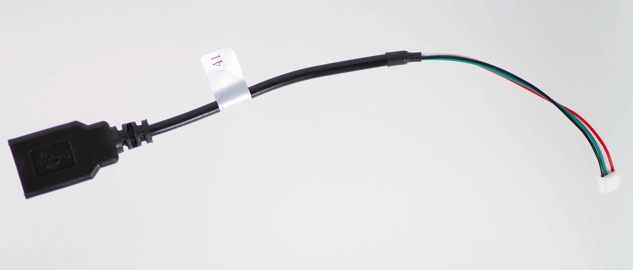
Description:
- 4-pin JST to USBA Female/Receptacle Cable
- 150mm (6”) version of MCBL-00009
Where Used:
- Used for connecting ModalAI USB Hosts (JST side, examples below) to USB Peripherals (Type A side)
- LTE Modem and USB Hub Addon J16 and J17 to USB peripheral device
- USB Expander and Debug Board to USB peripheral device
- Microhard and USB Hub Add-on USB J16 and J17 to USB peripheral device
- This cable is often included in many kits, but can be made available to purchase separately if you need it. Please use our contact page to reach out with inquiries.
Details:
| Component | Details |
|---|---|
| Connector A | JST, GHR-04V-S) |
| Connector B | USB 2.0 Type A Female/Receptacle |
| Length | ~150mm |
| Weight | 10.9 grams |
Pinout:
| A | B | ||
|---|---|---|---|
| 1 | VBUS (Source side) | 1 | VBUS (Load side) |
| 2 | DATA_M | 2 | D- |
| 3 | DATA_P | 3 | D+ |
| 4 | GND | 4 | GND |
MCBL-00048
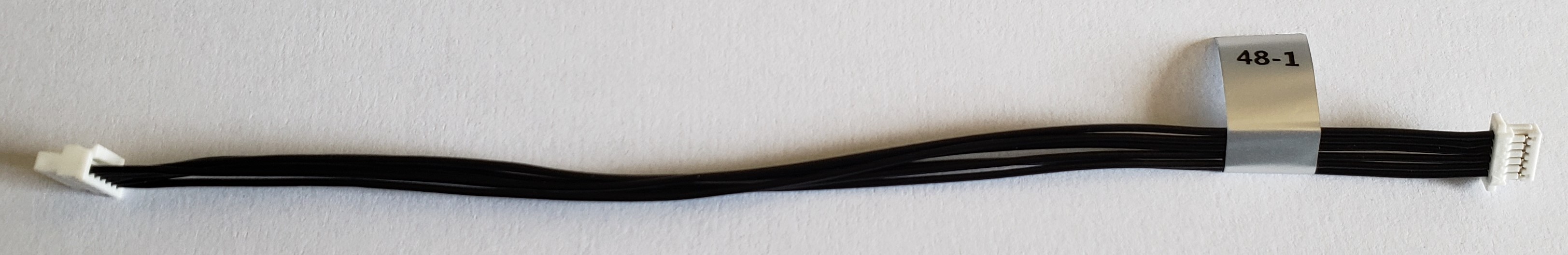
Description:
- Connects Matek GPS/Magnetometer unit to ModalAI DroneCode compliant ports, such as J10 on FlightCore V2
- This cable provides power + UART + I2C
Where Used:
- ModalAI FlightCore (v1 or V2) J10 (or other Dronecode compliant ports) to COTS Matek GNSS module, or others, with 6-pin JST SHR format (be sure to check GNSS module vendor specs as they change often)
Details:
| Component | Details |
|---|---|
| Connector A | JST 1.25mm GHR-06V-S, FCv2 side, +3.3V signal levels |
| Connector B | JST 1.0mm SHR-06V-S-B, Module side, +3.3V signal levels |
| Length | 150mm |
| Insulator | PVC (flexible) |
| Color | Black |
| Gauge | 26 AWG |
| Weight | 2.2 grams |
Pinout:
| A | FlightCore V2 | B | GNSS Module |
|---|---|---|---|
| 1 | 5V (Source) | 6 | 5V (Load) |
| 2 | UART_TX | 4 | UART_RX |
| 3 | UART_RX | 3 | UART_TX |
| 4 | MAG_I2C_SCL | 1 | SCL |
| 5 | MAG_I2C_SDA | 2 | SDA |
| 6 | GND | 5 | GND |
Pinout, Part Number, & Additional Specs: See Drawing Here Contact ModalAI on the Forum for .DXF or .DWG formats of this drawing.
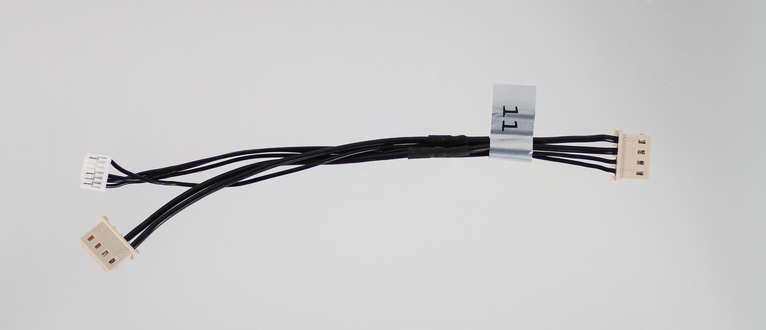
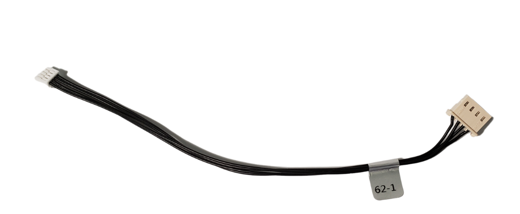
MCBL-00061
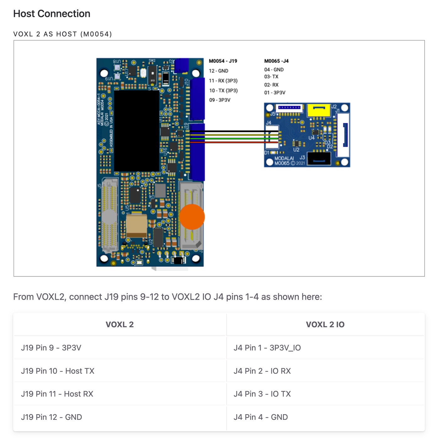
Description:
- Cable providing the primary connection used to connect VOXL 2 to VOXL 2 IO, which provides power and UART based communications
Where Used:
- Connects VOXL 2 J19 to VOXL 2 I/O J4
Details:
| Component | Details |
|---|---|
| Connector A | GHR-12V-S |
| Connector B | GHR-04V-S |
| Length | 150mm |
| Insulator | Silicone |
| Color | Black |
| Gauge | 26AWG |
Pinout:
| A | B | ||
|---|---|---|---|
| 1 | NC | ||
| 2 | NC | ||
| 3 | NC | ||
| 4 | NC | ||
| 5 | NC | ||
| 6 | NC | ||
| 7 | NC | ||
| 8 | NC | ||
| 9 | 3P3V | 1 | 3P3V_IO |
| 10 | VOXL 2 TX | 2 | VOXL 2IO RX |
| 11 | VOXL 2 RX | 3 | VOXL 2IO TX |
| 12 | GND | 4 | GND |
Pinout, Part Number, & Additional Specs: See Drawing Here Contact ModalAI on the Forum for .DXF or .DWG formats of this drawing.
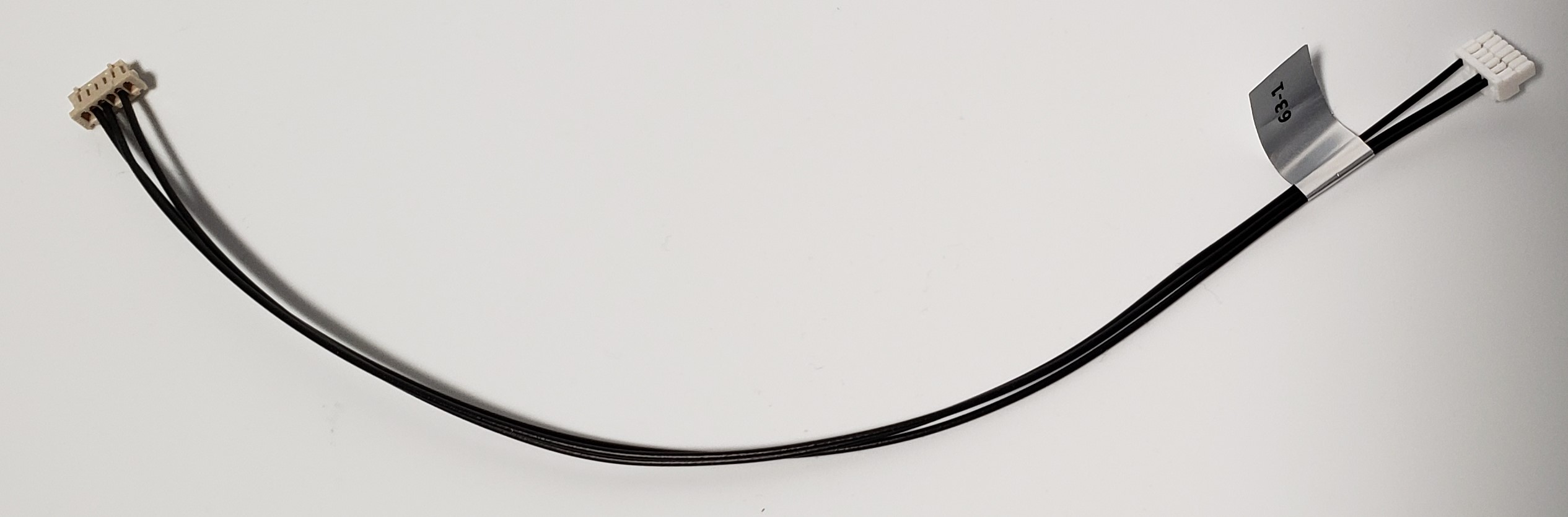
MCBL-00062
Description:
- Cable connecting the VOXL Power Module v3 to the Flight Core v2, providing power and I2C connections
- This is basically an MCBL-00001 (or MCBL-0003) but the LOAD side is now a 4-pin JST GH with a 1:1 pinout
- Note there are two variants, -1, and -2.
- -1, 150mm, is nominally for sale and the -2 is a shorter version at 75mm included in some drones (for sale upon request)
Where Used:
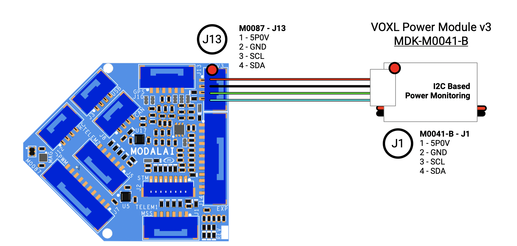
- Connects ModalAI Power Module V3 output connector to FlightCoreV2 J13
- Note, J13 is intended to be RED to help indicate Power. Due to supply chain challenges, some boards might have the standard white color connector for J13.
Details:
| Component | Details |
|---|---|
| Connector A | JST, GHR-04V-S |
| Connector B | Molex, 0050375043 |
| Length | 150mm (-1 variant), 75mm (-2 variant) |
| Insulator | Silicone (flexible) |
| Color | Black |
| Gauge | 26 AWG |
| Weight | 1.9 grams (-1), 1.3 grams (-2) |
Pinout:
| A | FCv2 Side | B | Power Module V3 Side |
|---|---|---|---|
| 1 | 5V DC (Load) | 1 | 5V DC (Source) |
| 2 | GND | 2 | GND |
| 3 | I2C_SCL | 3 | PM_SCL |
| 4 | I2C_SDA | 4 | PM_SDA |
Pinout, Part Number, & Additional Specs: See -1 Drawing Here, See -2 Drawing Here. Contact ModalAI on the Forum for .DXF or .DWG formats of this drawing.
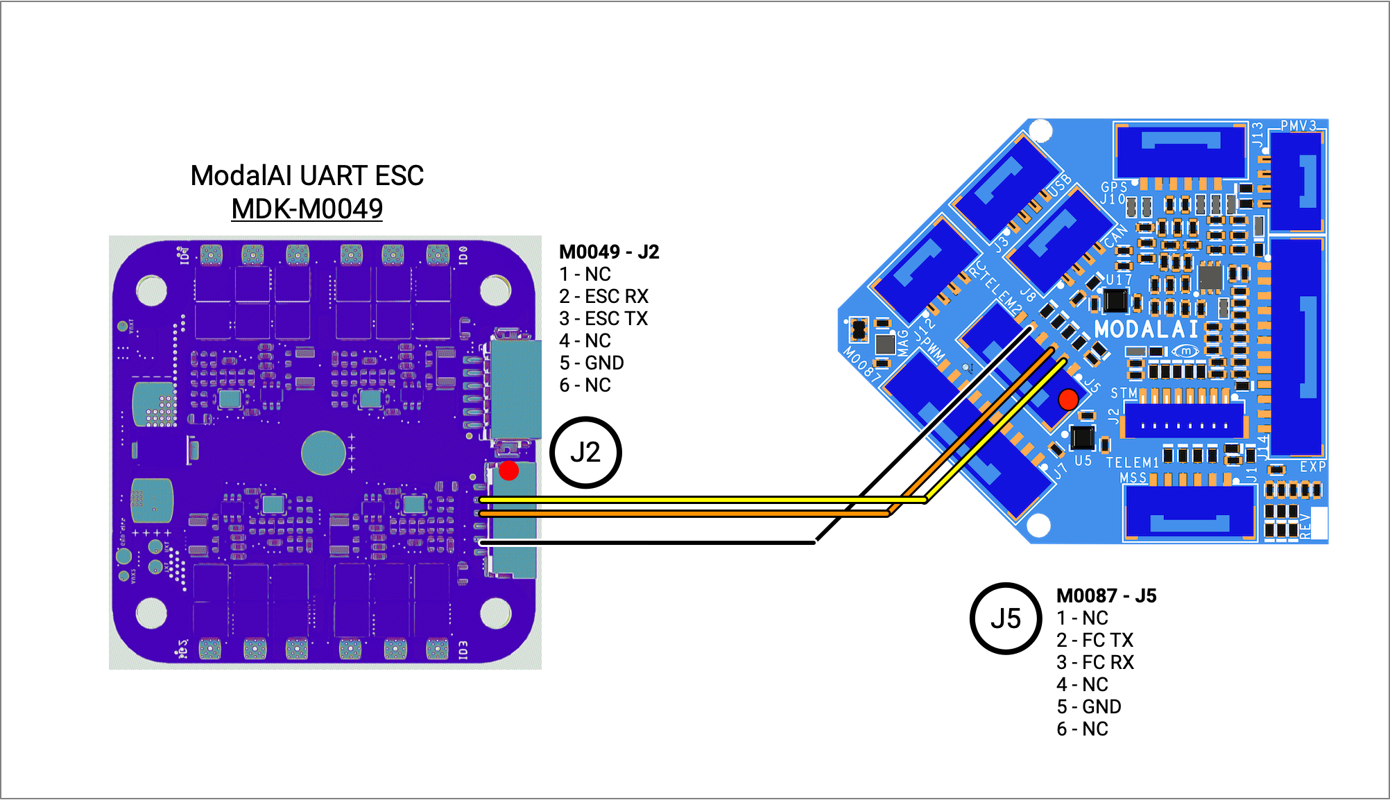
MCBL-00063
Description:
- Cable providing the primary connection used to connect Flight Core v2 to the ModalAI UART ESC.
- The cable is effectively a 6-pin JST version of the 4-pin JST used on MCBL-00029 (instead of a VOXL 2, use a FCv2 with Dronecode format).
- Note there are two variants, -1 and -2 with the only difference in length. -1 = 200mm, -2 = 90mm
Where Used:
- ModalAI ESC (M0049/M0117/M0134) J2 to FlightCoreV2 J5 (starting 1.13.2-0.1.2)
Details:
| Component | Details |
|---|---|
| Connector A | DF13-6S-1.25C (VOXL ESC), +3.3V levels |
| Connector B | JST 1.25mm GHR-06V-S, FCv2 side, +3.3V levels |
| Length | (-1 variant) 200mm, (-2 variant) 90mm |
| Insulator | PVC (flexible) |
| Color | Black |
| Gauge | 26 AWG |
| Weight | (-1 variant) 1.4 grams, (-2 variant) 0.9 grams |
Pinout:
| A | VOXL ESC V2/V3 | B | FlightCore V2 |
|---|---|---|---|
| 1 | - | 1 | |
| 2 | ESC RX | 2 | FCv2 TX |
| 3 | ESC TX | 3 | FCv2 RX |
| 4 | - | - | - |
| 5 | GND | 6 | GND |
| 6 | - | - | - |
Pinout, Part Number, & Additional Specs: See -1 Drawing Here & See -2 Drawing Here Contact ModalAI on the Forum for .DXF or .DWG formats of this drawing.
MCBL-00064
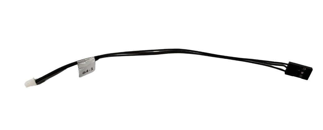
Description:
- RC Input (S.Bus, FrSky)
- Picks up Power on Red+Black, and Receive Signal on Orange from VOXL 2 I/O Board (M0065) to a R/C receiver 3-pin 0.1” hobby format
- Note: This is only intended for S.BUS (or +5V) remote receivers and cannot power high current servos or BLDCs
- Note: For Spektrum Receivers with +3.3V power supply needs, please see MCBL-00005
- This is just like MCBL-00018 but instead of needing two JST GH connectors, it has been consolidated into one 4-pin
Where Used:
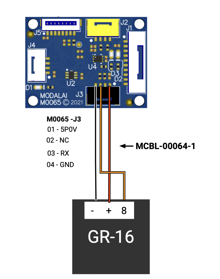
- 4-pin JST (connector B): VOXL 2 I/O (M0065) J3 (should be black in color, supply chain permitting) to 3-pin Harwin M20 Receptacle (connector A) to RC Receiver (e.g. S.BUS/FrSky)
| Component | Details |
|---|---|
| Connector B | JST GHR-04V-S, +5V Power/GND, UART_RX signal, +3.3V levels |
| Connector A | Harwin M20-1060300, CONN RCPT HSG 3POS 2.54mm (or similar) |
| Length | 150 mm |
| Insulator | PVC (flexible) |
| Color | Red/Black/Orange (might be all black) |
| Gauge | 26 AWG |
| Weight | 1.5 grams |
Pinout:
| A | RC Receiver | B | VOXL 2 IO (M0065) |
|---|---|---|---|
| 1 | Orange, S.Bus Signal (Output) | 3 | S.Bus signal (Input) |
| 2 | Red, +5V DC (Load) | 1 | +5V DC (Source) |
| 3 | BLACK, GND | 4 | GND |
MCBL-00065
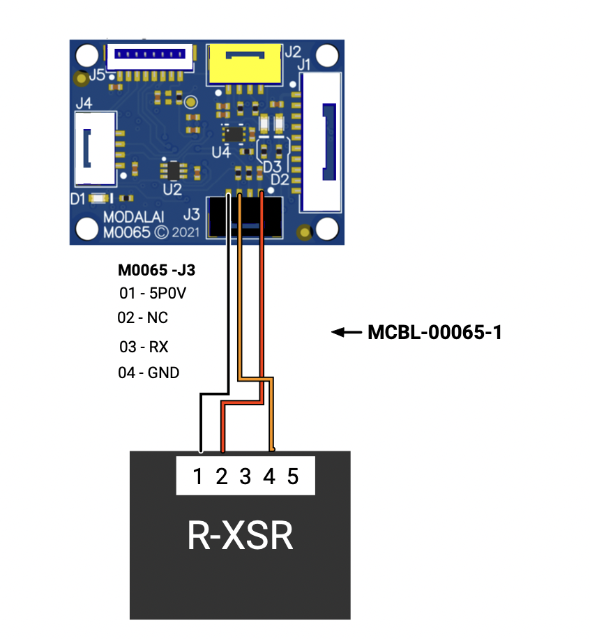
Description:
- RC Input (S.Bus, FrSky)
- Picks up Power on Red+Black, and Receive Signal on Orange from VOXL 2 I/O Board (M0065) to an FrSky R-XSR receiver 5-pin Molex Picoblade format
- Note: This is only intended for S.BUS (or +5V) remote receivers and cannot power high current servos or BLDCs
- This is just like MCBL-00021-1 but for VOXL 2 IO instead of FlightCore and therefore consolidated into one 4-pin JST
Where Used:
- 4-pin JST (connector B): VOXL 2 I/O (M0065) J3 (should be black in color, supply chain permitting) to 5-pin molex Picoblade on FrSky R-SSR RC Receiver
| Component | Details |
|---|---|
| Connector B | JST GHR-04V-S, +5V Power/GND, UART_RX signal, +3.3V levels |
| Connector A | Molex 0510210500, 5-position Picoblade housing 1.25mm |
| Length | 150 mm |
| Insulator | PVC (flexible) |
| Color | Red/Black/Orange (might be all black) |
| Gauge | 26 AWG |
Pinout:
MCBL-00021-1 shown but the same Picoblade pinout is used on MCBL-00065 as shown
| A | RC Receiver | B | VOXL 2 IO (M0065) |
|---|---|---|---|
| 2 | Orange, S.Bus Signal (Output) | 3 | S.Bus signal (Input) |
| 4 | Red, +5V DC (Load) | 1 | +5V DC (Source) |
| 5 | BLACK, GND | 4 | GND |
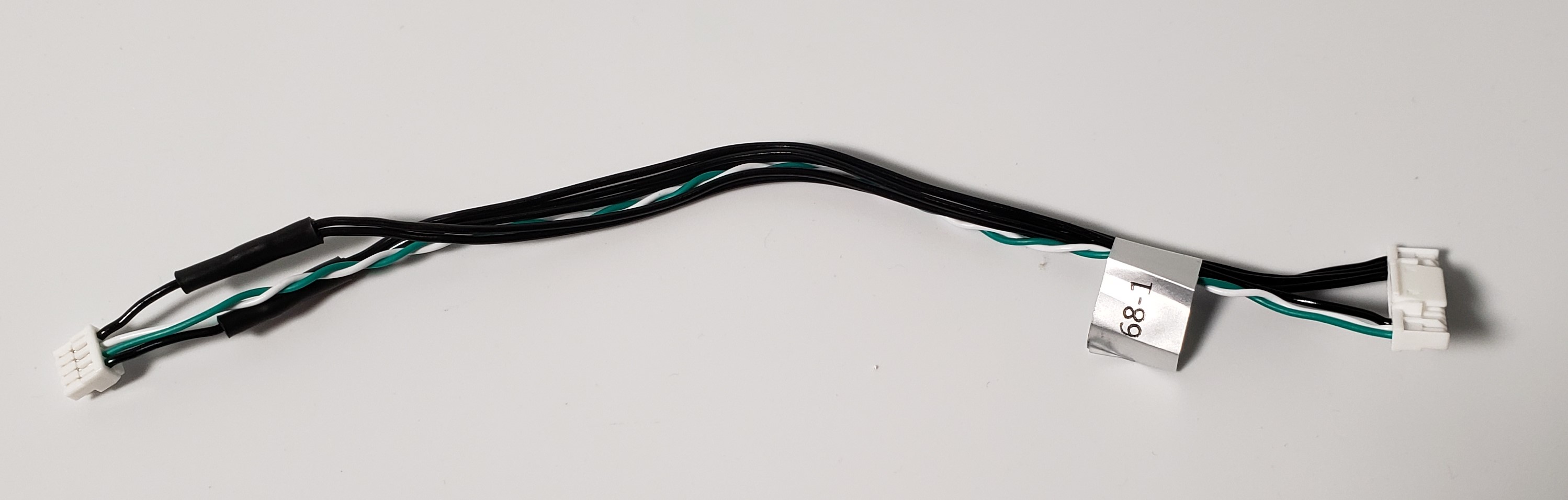
MCBL-00066
Description:
- Cable providing the primary connection used to connect Flight Core (V1 or v2) to the ModalAI 5G Modem (M0090)
- Compatible with other plug-in boards with the 6-pin JST format as listed here.
- The cable is effectively a 6-pin JST version of the 4-pin JST used on MCBL-00067.
Where Used:
- ModalAI VOXL 2 5G Plug In Board (M0090) J9 to FlightCore V1/V2 J5 (or other DroneCode compliant UART ports on the designs, Software dependant)
- This can also be used on other ModalAI DroneCode compliant UART ports (6-pin JST GH), but Software mapping would require changes by the user.
Details:
| Component | Details |
|---|---|
| Connector A | JST 1.25mm GHR-06V-S, VOXL 2 side, +3.3V levels |
| Connector B | JST 1.25mm GHR-06V-S, FCv2 side, +3.3V levels |
| Length | 250mm |
| Insulator | Silicon (flexible) |
| Color | Black |
| Gauge | 26 AWG |
| Weight | 1.9 grams |
Pinout:
| A | VOXL 2 J9 | B | FlightCore V2 J5 |
|---|---|---|---|
| 1 | - | 1 | |
| 2 | UART TX (Output) | 3 | FCv2 UART RX (Input) |
| 3 | UART RX (Input) | 2 | FCv2 UART TX (Output) |
| 4 | - | - | - |
| 5 | - | - | |
| 6 | GND | 6 | GND |
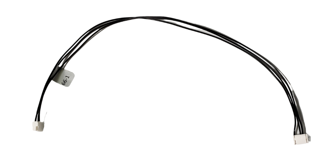
MCBL-00067
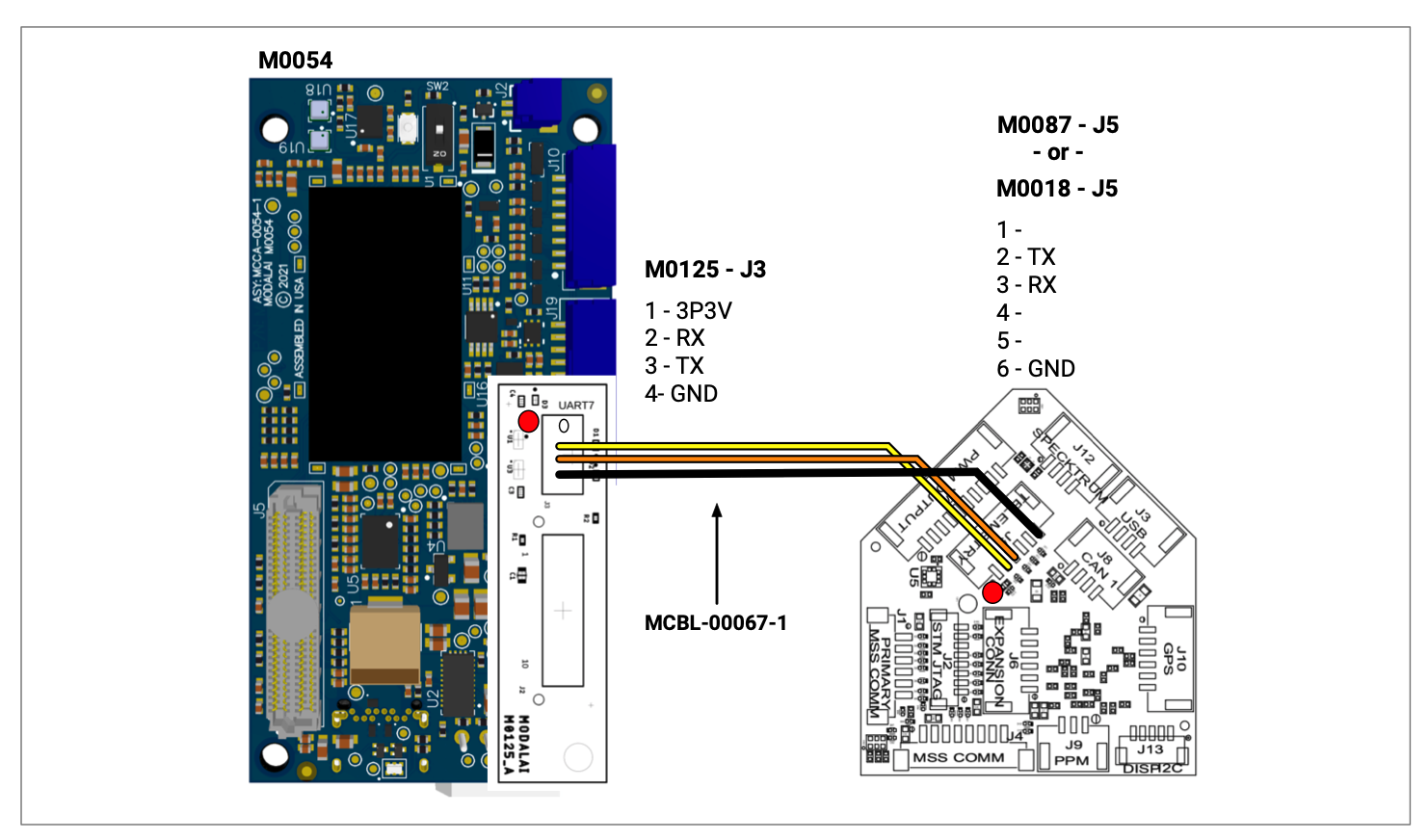
Description:
- Cable providing the primary connection used to connect Flight Core (V1 or v2) to the ModalAI USB and UART Breakout Board (M0125)
- Compatible with other plug-in boards with the 6-pin JST format as listed here.
- The cable is effectively a 4-pin JST version of the 6-pin JST used on MCBL-00066.
Where Used:
- ModalAI VOXL 2 USB and UART Breakout Board (M0125) J3 to FlightCore V1/V2 J5 (or other DroneCode compliant UART ports on the designs, Software dependant)
- This can also be used on other ModalAI DroneCode compliant UART ports (6-pin JST GH), but Software mapping would require changes by the user.
- Note: M0125 4-Pin JST UART port has RX on pin 2 and TX on pin 3, this is not common across our other HW designs (it was done intentionally, so be careful)
Details:
| Component | Details |
|---|---|
| Connector A | JST 1.25mm GHR-04V-S, VOXL 2 side, +3.3V levels |
| Connector B | JST 1.25mm GHR-06V-S, FCv2 side, +3.3V levels |
| Length | 250mm |
| Insulator | Silicon (flexible) |
| Color | Black |
| Gauge | 26 AWG |
| Weight | 1.9 grams |
Pinout:
| A | M0125 UART Breakout J3 | B | FlightCore V2 J5 |
|---|---|---|---|
| 1 | - | 1 | |
| 2 | UART RX (Input) | 2 | FCv2 UART TX (Output) |
| 3 | UART TX (Output) | 3 | FCv2 UART RX (Input) |
| 4 | GND | 6 | GND |
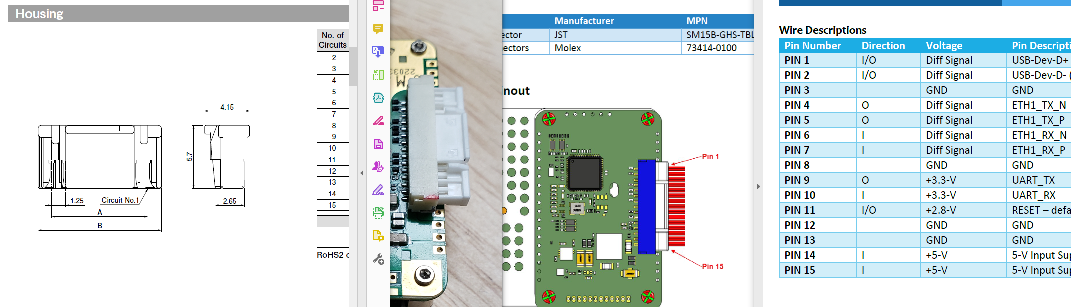
MCBL-00068
Description:
- Cable providing a 4-pin JST USB connection from a VOXL 2 Plug-in Board (M0090, M0130, etc) to a Doodle Labs Helix Smart Radio Primary connector
- Compatible with any ModalAI 4-pin JST USB connectors on various designs
- Note: Standalone versions of our USB boards require a stable high-power source that can deliver 5W to the Helix
- Note: Doodle Labs Pinout notations in their documents has an incorrect pin1-pin15 callout. They are aware of it and will eventually fix it. We show an image below to help users understand this as our drawings use the proper JST based notations for pin 1
Where Used:
- VOXL 2 + M0090 (5G modem)
- VOXL 2 + M0130 (4G Modem, coming soon!!)
- VOXL 2 + M0078 USB Debug Board
Details:
| Component | Details |
|---|---|
| Connector A | JST 1.25mm GHR-04V-S, VOXL 2 side |
| Connector B | JST 1.25mm GHR-15V-S, Doodle Labs Helix side |
| Length | 150mm |
| Insulator | PVC (flexible) |
| Color | Black |
| Gauge | 26AWG (Power/GND), 28AWG USB Data |
| Weight | 2.6 grams |
Pinout:
| A | VOXL 2 Side | B | Doodle Labs Helix 15-pin Side |
|---|---|---|---|
| 1 | VBUS (Source) | 1 & 2 | VCC/VBUS (Load), 2-way splice |
| 2 | USB_D- | 14 | D- |
| 3 | USB_D+ | 15 | D+ |
| 4 | GND | 3 & 4 & 13 | GND, 3-way splice |
Pinout, Part Number, & Additional Specs: See Drawing Here Contact ModalAI on the Forum for .DXF or .DWG formats of this drawing.
MCBL-00069
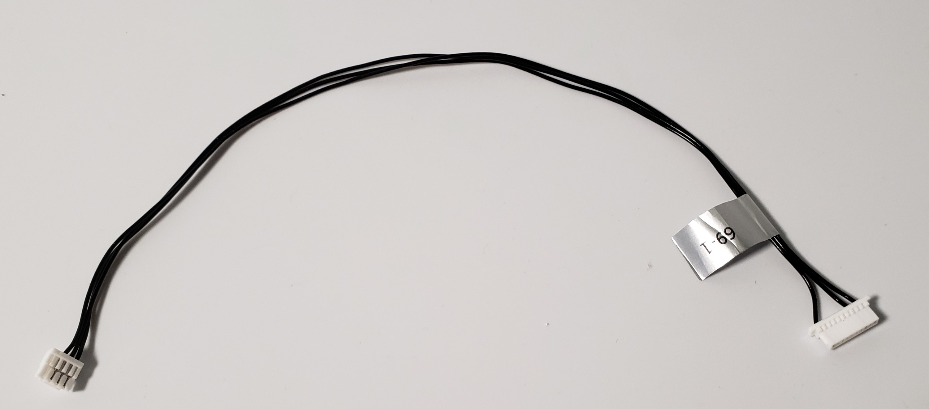
Description:
- Cable providing the VOXL 2 ESC UART 4-pin JST to a TMotor F55A ESC
- Note: The TMotor F55A ESC has custom ModalAI firmware and hardware mods on it, thus allowing operation as noted here for the UART lines and the 4 MCUs. If you did not buy the TMotor ESC through ModalAI, this will not work
Where Used:
- VOXL 2 + TMotor F55A ESC
Details:
| Component | Details |
|---|---|
| Connector A | JST 1.25mm GHR-04V-S, VOXL 2 side, +3.3V signal levels |
| Connector B | JST 1.0mm SHR-10V-S-B, F55A ESC, +3.3V signal levels |
| Length | 200mm |
| Insulator | PVC (flexible) |
| Color | Black |
| Gauge | 28 AWG |
| Weight | 1.1 grams |
Pinout:
| A | VOXL 2 Side | B | TMotor Connector Side |
|---|---|---|---|
| 1 | - | - | |
| 2 | UART_TX (Output of V2) | 1 | ESC UART RX (Input to ESC) |
| 3 | UART_RX (Input to V2) | 3 | ESC UART TX (Output of ESC) |
| 4 | GND | 10 | GND |
This image shows the standard pinout for reference, but we use the signals as follows due to custom mods: 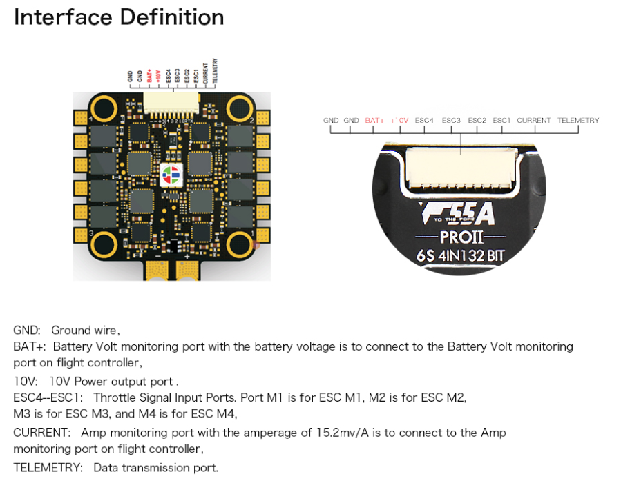
- TELEM Data output set as ESC UART Input
- ESC[1:4] set as ESC UART Outputs
Pinout, Part Number, & Additional Specs: See Drawing Here Contact ModalAI on the Forum for .DXF or .DWG formats of this drawing.
MCBL-00070
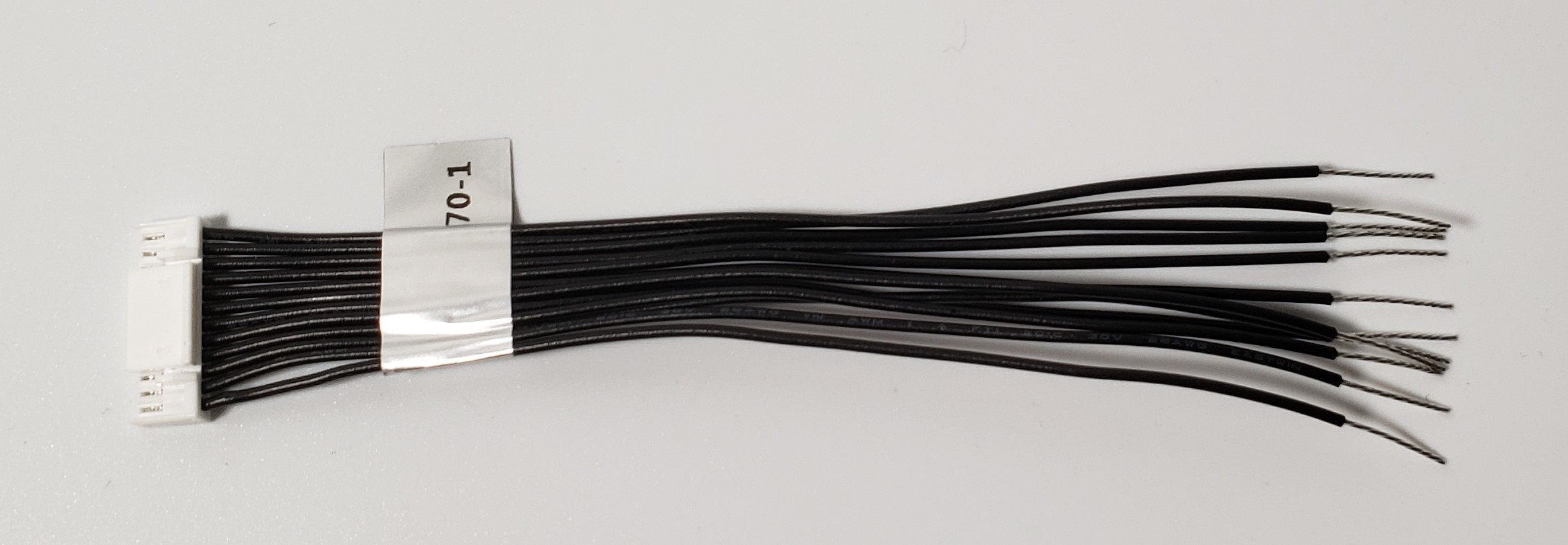
Description:
- Cable providing a full JST GH 12-pin breakout
Where Used:
- VOXL 2 J19, M0130 4G Modem J8
- Any ModalAI 12-pin JST where soldering or custom harnesses are needed
- Note: pigtail side is tinned for ~10mm making it easy to install JST SSHL-002T-P0.2 pins if needed
- Great item to have for making your own cables!!
Details:
| Component | Details |
|---|---|
| Connector A | JST 1.25mm GHR-12V-S |
| Connector B | None: Pigtails |
| Length | 100mm |
| Insulator | PVC |
| Color | Black |
| Gauge | 26 AWG |
| Weight | 3.0 grams |
Pinout:
| A | |||
|---|---|---|---|
| 1 | 1 | (pigtail) | |
| 2 | 2 | (pigtail) | |
| 3 | 3 | (pigtail) | |
| 4 | 4 | (pigtail) | |
| 5 | 5 | (pigtail) | |
| 6 | 6 | (pigtail) | |
| 7 | 7 | (pigtail) | |
| 8 | 8 | (pigtail) | |
| 9 | 9 | (pigtail) | |
| 10 | 10 | (pigtail) | |
| 11 | 11 | (pigtail) | |
| 12 | 12 | (pigtail) |
Pinout, Part Number, & Additional Specs: See Drawing Here Contact ModalAI on the Forum for .DXF or .DWG formats of this drawing.
MCBL-00071
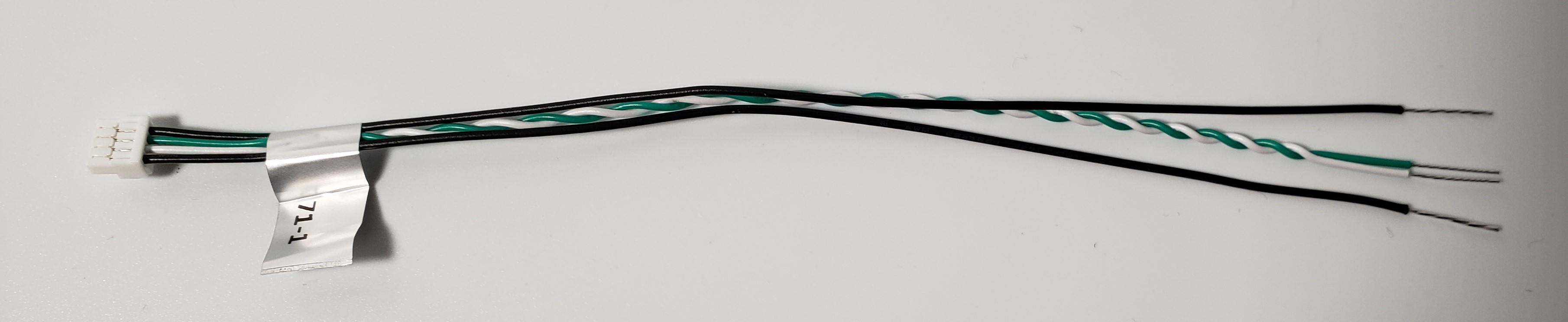
Description:
- Cable providing a full JST GH 4-pin breakout, but with Pins 2&3 as twisted pair, suited for all of ModalAI’s USB2 ports
Where Used:
- VOXL or VOXL 2 Plug-In boards
- Microhard Plug-ins (M0048), Sierra 4G Plug-ins (M0030, M0130), 5G Plug-ins (M0090)
- Any ModalAI 4-pin JST where soldering or custom harnesses are needed
- Note: pigtail side is tinned for ~10mm making it easy to install JST SSHL-002T-P0.2 pins if needed
- Great item to have for making your own cables!!
Details:
| Component | Details |
|---|---|
| Connector A | JST 1.25mm GHR-04V-S |
| Connector B | None: Pigtails |
| Length | 150mm |
| Insulator | PVC |
| Color | Black, White/Green TP |
| Gauge | 26 AWG, 28AWG Twisted Pair (Pins 2&3) |
| Weight | 1.3 grams |
Pinout:
| A | |||
|---|---|---|---|
| 1 | 1 | (pigtail) | |
| 2 | 2 | (pigtail, TP) | |
| 3 | 3 | (pigtail, TP) | |
| 4 | 4 | (pigtail) |
Pinout, Part Number, & Additional Specs: See Drawing Here Contact ModalAI on the Forum for .DXF or .DWG formats of this drawing.
MCBL-00072
Description:
- VOXL 2 10-pin JST USB to Boson RHP-BOS-VPC3-IF 6-JST
- Cable providing a direct connection from ModalAI’s USB3 ports (M0090, M0130) to a FLIR Boson that uses the RHP-BOS-VPC3-IF “backpack”
- Note: Only picks up the USB2 bus and not the SuperSpeed signals, so bandwidth would be limited to the 480Mbps USB2 standard
- For the 4-pin USB2 connector version instead of the 10-pin, see MCBL-00107
Where Used:
- VOXL 2 Modem or USB3 expansion boards
- Sierra 4G Plug-ins (M0130), 5G Plug-ins (M0090)
Details:
| Component | Details |
|---|---|
| Connector A | 10 POS 1.25mm JST, GHR-10V-S, VOXL 2 USB3 10-pin |
| Connector B | 6 POS 1.00mm JST, SHR-06V-S-B, Backpack side |
| Length | 70mm |
| Insulator | PVC |
| Color | Black (VBUS/GND), White/Green Twisted Pair USB_D+/D- |
| Gauge | Black 26 AWG, White/Green TP 28AWG |
| Weight | 0.9 grams |
Pinout:
| A | B | ||
|---|---|---|---|
| 1 | VBUS (Source) | 1 | 5VDC (Load) |
| 2 | USB_D- | 6 | Boson D- |
| 3 | USB_D+ | 5 | Boson D+ |
| 4 | GND | 2 | GND |
| 5 | - | - | - |
| 6 | - | - | - |
| 7 | - | - | - |
| 8 | - | - | - |
| 9 | - | - | - |
| 10 | - | - | - |
Pinout, Part Number, & Additional Specs: See Drawing Here Contact ModalAI on the Forum for .DXF or .DWG formats of this drawing.
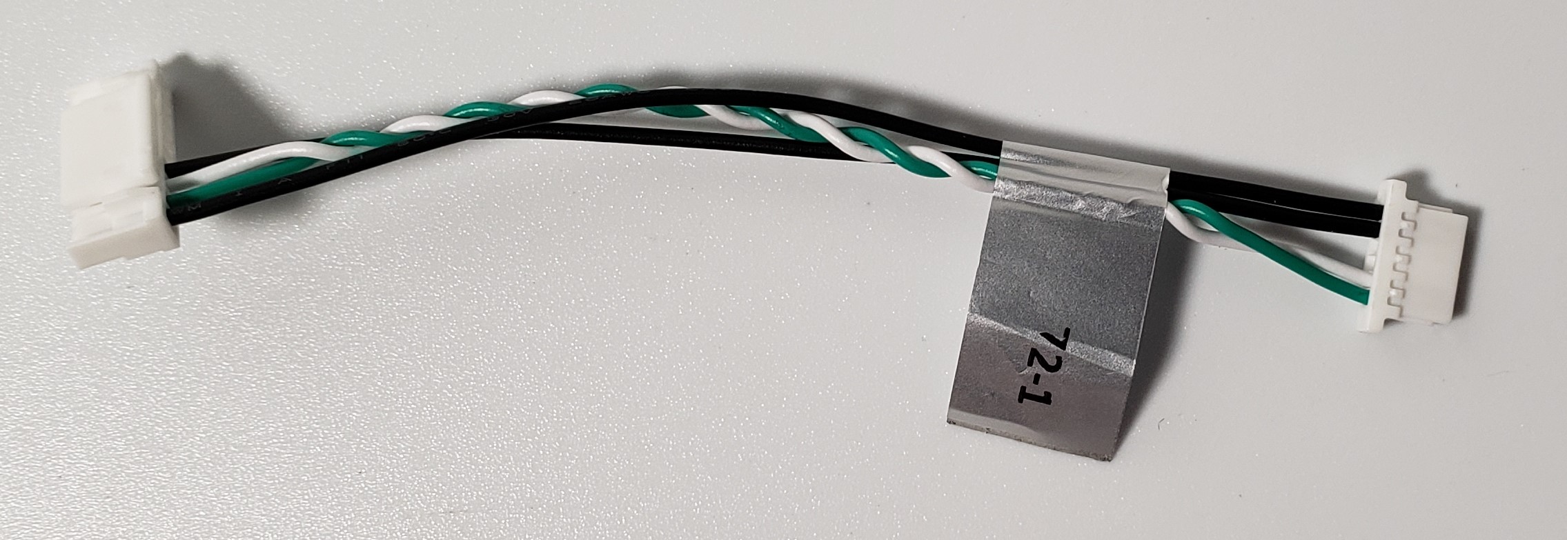
MCBL-00076
Description:
- Connects VOXL 2/VOXL 2-Mini J19 in the Starling or Sentinel Drone Platform to Matek GPS/Magnetometer M10 unit (DroneCode compliant) and pigtails for soldering to a R/C unit UART+PWR
- This cable provides power (GNSS+RC) + UART (GNSS) + I2C (MAG) + UART (R/C)
- Note there are two variants, -1, and -3.
- “-1” is included in the Starling platform for shorter cable length installations.
- “-3” is longer intended for the Sentinel platform installations.
Where Used:
- ModalAI Starling Drone, with either VOXL 2 or VOXL 2-Mini
- ModalAI Sentinel Drone, with either VOXL 2 or VOXL 2-Mini
Details:
| Component | Details |
|---|---|
| Connector A | JST 1.25mm GHR-12V-S, VOXL 2 side, +3.3V signal levels |
| Connector B | JST 1.25mm GHR-06V-S, Module side, +3.3V signal levels |
| Connector C | Pigtails for soldering to R/C unit, +3.3V signal levels |
| Length | 100mm (CONA-CONB), 45mm pigtails (-1) |
| 250mm (CONA-CONB), 155mm pigtails (-3) | |
| Insulator | Silicone |
| Color | Black, Red, White, Yellow |
| Gauge | 28 AWG |
| Weight | 1.7 grams (-1), 3.4 grams (-3) |
Pinout:
| A | VOXL 2/ VOXL 2-Mini | B | GNSS Module | C | Pigtails |
|---|---|---|---|---|---|
| 1 | 5V (Source) | 1 | 5V (Load) | PG1 | R/C 5V (Red, Load) |
| 2 | UART_TX | 2 | UART_RX | ||
| 3 | UART_RX | 3 | UART_TX | ||
| 4 | MAG_I2C_SCL | 4 | SCL | ||
| 5 | MAG_I2C_SDA | 5 | SDA | ||
| 6 | GND | 6 | GND | ||
| 10 | UART_TX | PG2 | R/C_RX (White) | ||
| 11 | UART_RX | PG3 | R/C_TX (Yellow | ||
| 12 | GND | PG4 | R/C GND (Black) |
Pinout, Part Number, & Additional Specs: See -1 Drawing Here and See -3 Drawing Here Contact ModalAI on the Forum for .DXF or .DWG formats of this drawing.
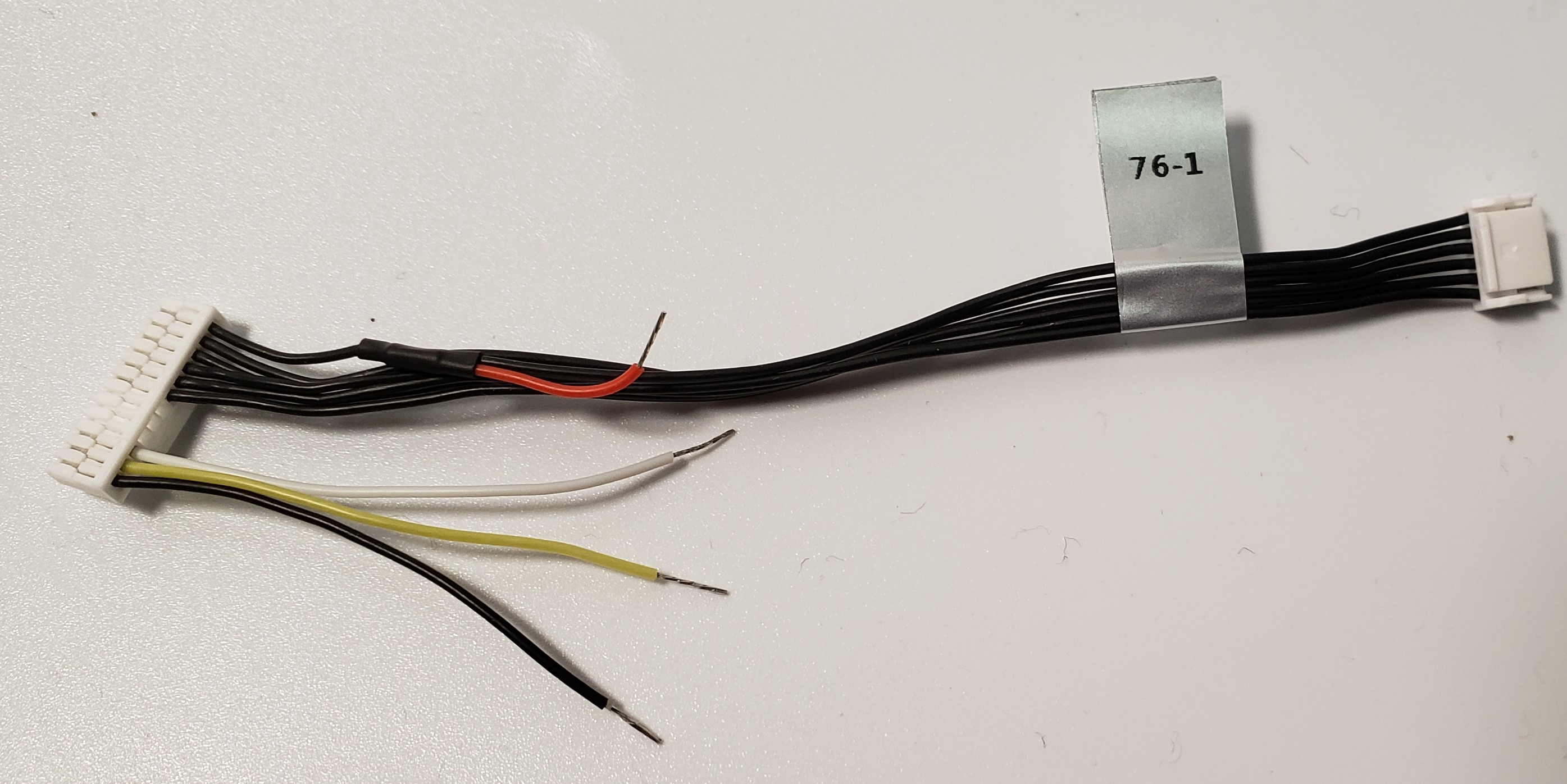
MCBL-00078
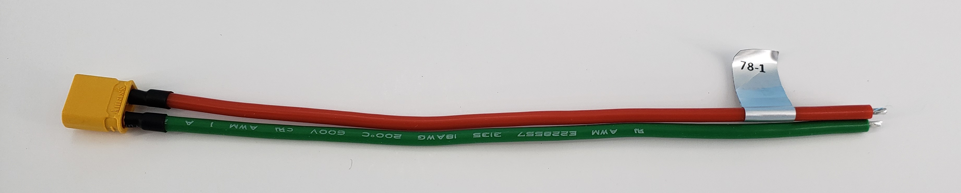
Description:
- Multi-Purpose XT30 Male to Pigtail Leads, 150mm
- Easily identifiable RED (+) and GREEN (-) cables
- Robust adhesive lined heatshrink for long-lasting protection of pin solder joints
Where used:
- Included in Starling ESC for system power from battery
- Useful for ESC side or target side electronics when using an XT30-F based battery
Details:
| Component | Details |
|---|---|
| Connector A | AMASS, XT30U-M |
| Connector B | Pigtails, stripped and tinned 3.5mm |
| Length | 150mm (-1 variant) |
| Insulator | Silicon |
| Color | Red (+) and Green (-) |
| Gauge | 18 AWG |
| Weight | 5.4 grams (-1 variant) |
| A | B | ||
|---|---|---|---|
| + | + | + | RED |
| - | - | - | GREEN |
Pinout, Part Number, & Additional Specs: See Drawing Here. Contact ModalAI on the Forum for .DXF or .DWG formats of these drawings.
MCBL-00080
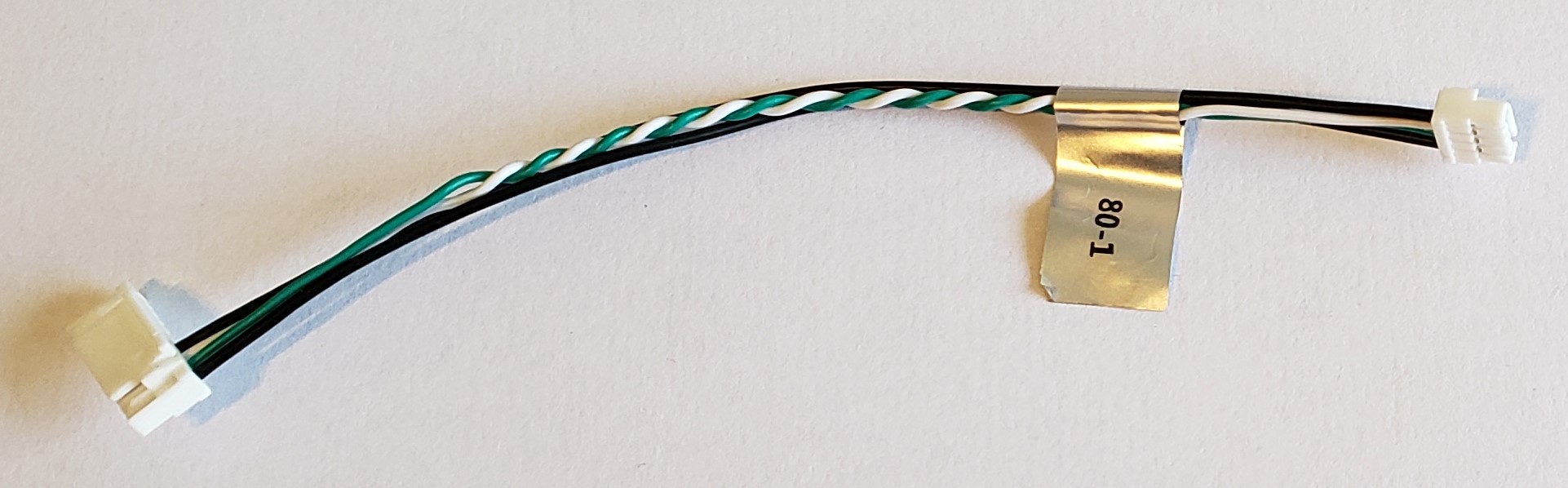
Description:
- USB3 10-pin JST cable to USB2 4-Pin JST GH plug
- There are two variants currently: -1 at the nominal 100mm and a -2 at a shorter 50mm length.
Where Used:
- Any ModalAI CCA USB downstream port (host only) with the 10-pin JST ModalAI USB3 format (examples are M0062, M0067, M0090, M0104, M0130).
- Ideal for connecting standalone modules (Microhard, LTE) to the VOXL 2 Mini platform (standalone dongles still require independent power from MCBL-00017-1)
Details:
| Component | Details |
|---|---|
| Connector A | 10POS 1.25mm JST, GHR-10V-S |
| Connector B | 4POS 1.25mm JST, GHR-04V-S |
| Length | 100mm (-1 variant), 50mm (-2 variant) |
| Insulator | PVC |
| Color | Black, White/Green TP |
| Gauge | 26AWG VBUS/GND, 28AWG Twisted Pair Signals |
| Weight | 1.2 grams (-1 variant), 0.8 grams (-2 variant) |
Pinout:
| A | B | ||
|---|---|---|---|
| 1 | VBUS (Source) | 1 | VBUS (Load) |
| 2 | USB_D- | 2 | D- |
| 3 | USB_D+ | 3 | D+ |
| 4 | GND | 4 | GND |
| 5 | NC | ||
| 6 | NC | ||
| 7 | NC | ||
| 8 | NC | ||
| 9 | NC | ||
| 10 | NC |
Pinout, Part Number, & Additional Specs: See -1 Drawing Here, See -2 Drawing Here Contact ModalAI on the Forum for .DXF or .DWG formats of this drawing.
MCBL-00081
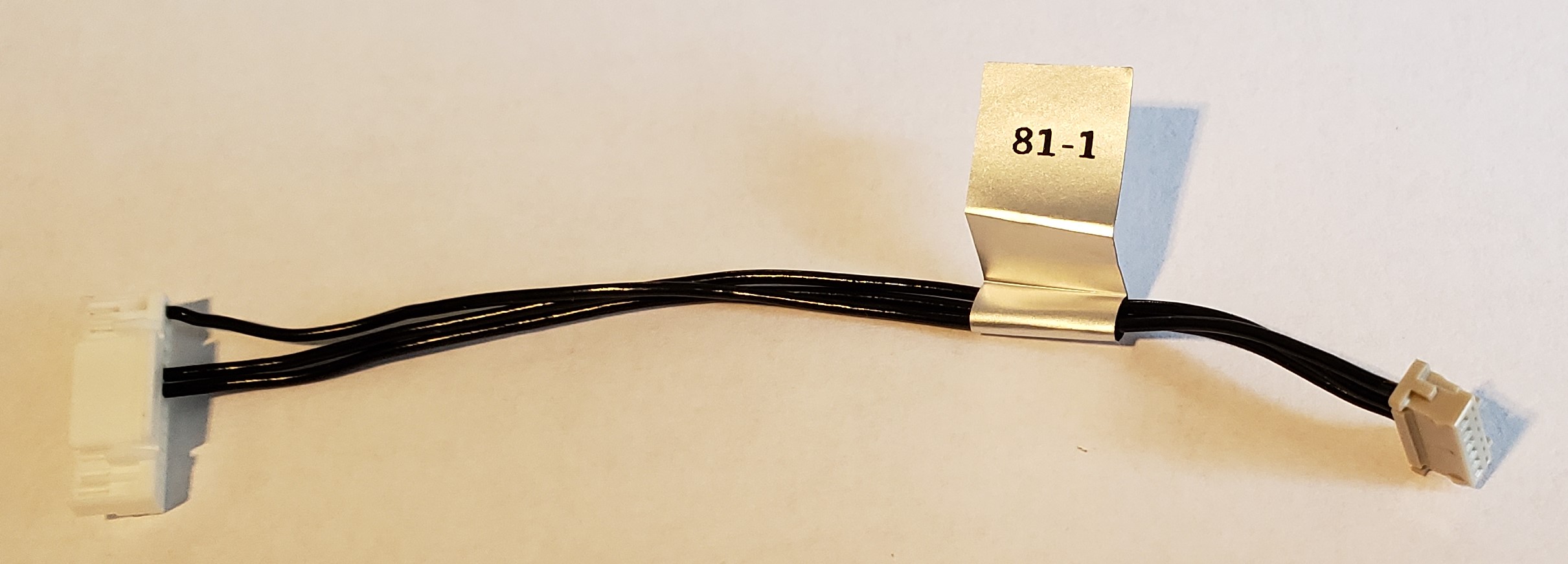
Description:
- Cable providing the ESC UART connection between VOXL 2 Mini and ModalAI ESC V2 (M0049, M0117, M0134).
Where Used:
- Connects VOXL 2 Mini J19 to ModalAI ESC V2 J2
Details:
| Component | Details |
|---|---|
| Connector A | GHR-12V-S |
| Connector B | DF13-6S-1.25C |
| Length | 90mm |
| Insulator | PVC (flexible) |
| Color | Black |
| Gauge | 26AWG |
| Weight | 0.9 grams |
Pinout:
| A | B | ||
|---|---|---|---|
| 1 | NC | ||
| 2 | NC | ||
| 3 | NC | ||
| 4 | NC | ||
| 5 | NC | ||
| 6 | NC | ||
| 7 | UART_TX | 2 | ESC_RX |
| 8 | UART_RX | 3 | ESC_TX |
| 9 | NC | ||
| 10 | NC | ||
| 11 | NC | ||
| 12 | GND | 5 | GND |
Pinout, Part Number, & Additional Specs: See Drawing Here Contact ModalAI on the Forum for .DXF or .DWG formats of this drawing.
MCBL-00082
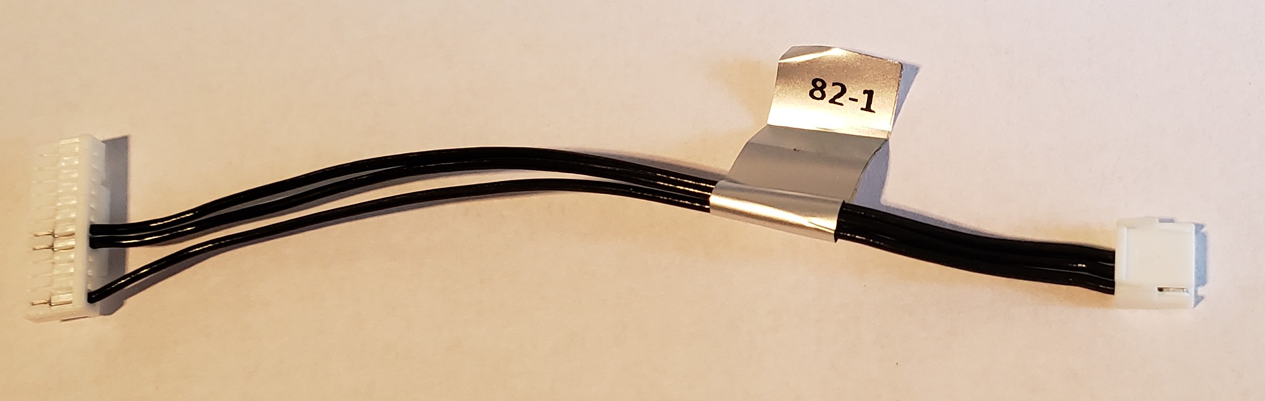
Description:
- Cable providing the ESC UART connection between VOXL 2 Mini and ModalAI Mini ESC (M0129).
Where Used:
- Connects VOXL 2 Mini J19 to ModalAI Mini ESC J1
Details:
| Component | Details |
|---|---|
| Connector A | GHR-12V-S |
| Connector B | GHR-04V-S |
| Length | 90mm |
| Insulator | PVC (flexible) |
| Color | Black |
| Gauge | 26AWG |
| Weight | 0.9 grams |
Pinout:
| A | B | ||
|---|---|---|---|
| 1 | NC | ||
| 2 | NC | ||
| 3 | NC | ||
| 4 | NC | ||
| 5 | NC | ||
| 6 | NC | ||
| 7 | UART_TX | 2 | ESC_RX |
| 8 | UART_RX | 3 | ESC_TX |
| 9 | NC | ||
| 10 | NC | ||
| 11 | NC | ||
| 12 | GND | 4 | GND |
Pinout, Part Number, & Additional Specs: See Drawing Here Contact ModalAI on the Forum for .DXF or .DWG formats of this drawing.
MCBL-00083
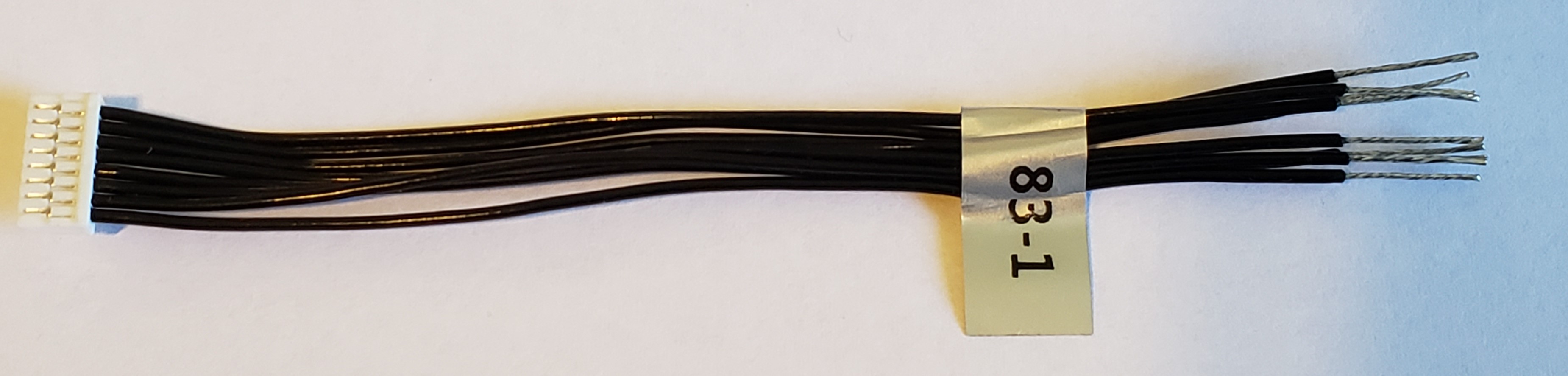
Description:
- Cable providing a full JST GH 8-pin breakout
Where Used:
- VOXL 2 & VOXL 2 Mini J10
- Any ModalAI 8-pin JST where soldering or custom harnesses are needed
- Note: pigtail side is tinned for ~10mm making it easy to install JST SSHL-002T-P0.2 pins if needed
- Great item to have for making your own cables!!
Details:
| Component | Details |
|---|---|
| Connector A | JST 1.25mm GHR-08V-S |
| Connector B | None: Pigtails |
| Length | 100mm + 10mm pigtails |
| Insulator | PVC |
| Color | Black |
| Gauge | 26 AWG |
| Weight | 2.1 grams |
Pinout:
| A | |||
|---|---|---|---|
| 1 | 1 | (pigtail) | |
| 2 | 2 | (pigtail) | |
| 3 | 3 | (pigtail) | |
| 4 | 4 | (pigtail) | |
| 5 | 5 | (pigtail) | |
| 6 | 6 | (pigtail) | |
| 7 | 7 | (pigtail) | |
| 8 | 8 | (pigtail) |
Pinout, Part Number, & Additional Specs: See Drawing Here Contact ModalAI on the Forum for .DXF or .DWG formats of this drawing.
MCBL-00084
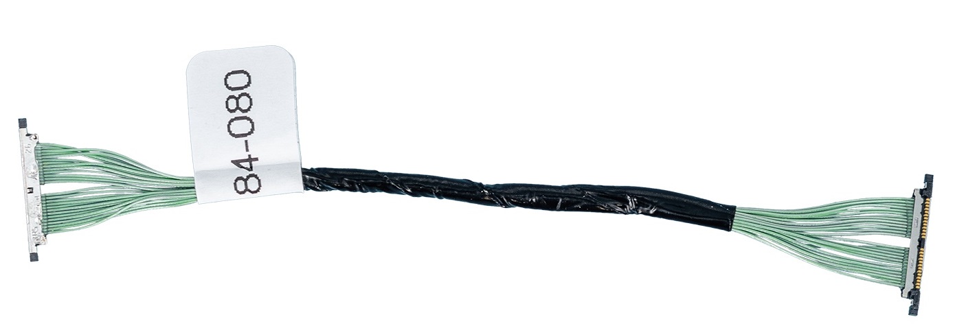
Description:
Where Used:
- VOXL 2 with M0173 Starling Front-end
Details:
| Component | Details |
|---|---|
| Connector A | |
| Connector B | |
| Length | |
| Insulator | |
| Color | |
| Gauge | |
| Weight |
Pinout:
| A | ||
|---|---|---|
| 1 |
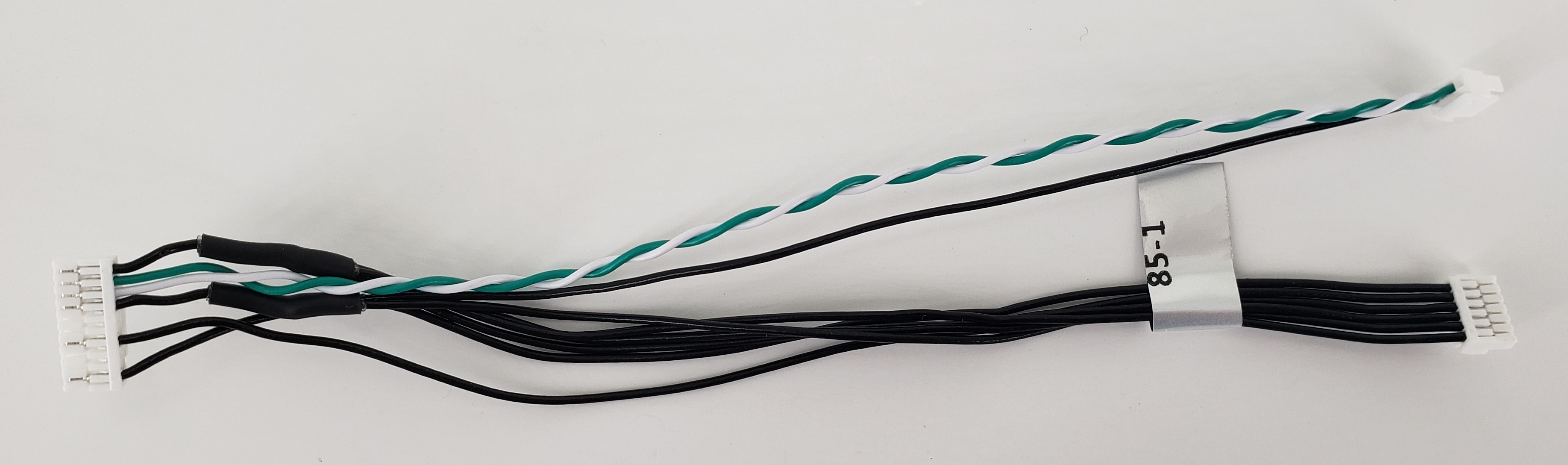
MCBL-00085
Description:
- Cable providing a 10-pin JST USB + Power connection from a VOXL 2 Plug-in Board (Sierra 4G Modem, M0130) to a Doodle Labs Mesh Rider Mini RM-2025-62M3 Smart Radio Port 1 (Data) and Port 4 (Power) connectors
- Compatible with any ModalAI 10-pin JST USB connectors on various designs,
- Note: Only M0130 (4G Sierra Modem for VOXL 2) at this time can supply the 2A needed on VBUS for the 10W max power use case reported in the device spec by Doodle Labs. Other 10-pin format designs (M0062, M0090, M0144) will work but range may be limited.
Where Used:
- VOXL 2 + M0090 (5G modem, <10W capable VBUS)
- VOXL 2 + M0130 (4G Modem, 10W capable VBUS)
- VOXL 2 + M0078 USB Debug Board (configurable VBUS)
Details:
| Component | Details |
|---|---|
| Connector A | JST 1.25mm GHR-10V-S, VOXL 2 Plug-In Board side |
| Connector B | JST 1.25mm GHR-06V-S, Doodle Labs Helix side, Port 4, Power |
| Connector c | JST 1.25mm GHR-04V-S, Doodle Labs Helix side, Port 1, USB Data |
| Length | 150mm |
| Insulator | PVC |
| Color | Black (Power + GND), White/Green TP (USB) |
| Gauge | 26AWG (Power/GND), 28AWG USB Data |
| Weight | 3.7 grams |
Pinout:
| A | VOXL 2 Host (M0130, Source) | B | Mesh Rider Mini Port4 (Power, Load) | C | Mesh Rider Mini Port1 (USB Data) |
|---|---|---|---|---|---|
| 1 | 5V VBUS (Source) | 1,2,3 | 5V DC (Load) | - | - |
| 2 | D- | - | - | 2 | D- |
| 3 | D+ | - | - | 3 | D+ |
| 4 | GND | 4 | GND | 4 | GND |
| 7 | GND | 5 | GND | - | - |
| 10 | GND | 6 | GND | - | - |
Image Courtesy of Doodle Labs minioem-v0323.pdf (miniOEM Mesh Rider Radio – Connector Descriptions (2023 Update)) 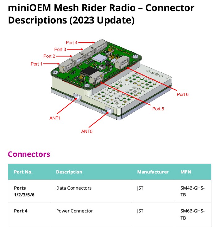
Pinout, Part Number, & Additional Specs: See Drawing Here Contact ModalAI on the Forum for .DXF or .DWG formats of this drawing.
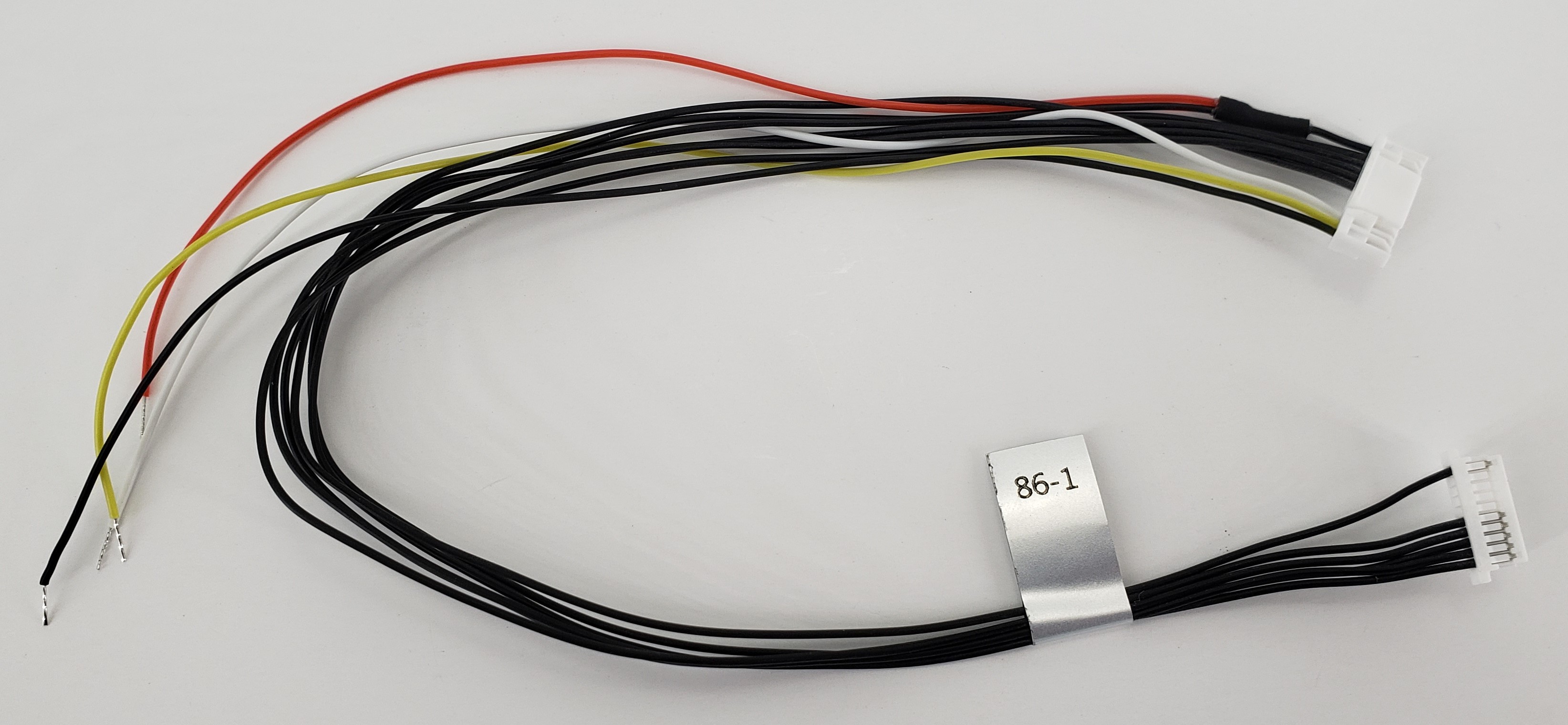
MCBL-00086
Description:
- Connects VOXL 2 J19 in the Sentinel Drone Platform to Holybro GPS/Magnetometer unit (Not DroneCode compliant) and pigtails for soldering to a R/C unit UART+PWR
- This cable provides power (GNSS+RC) + UART (GNSS) + I2C (MAG) + UART (R/C)
- The case lid is opened, supplied cable is removed, and this cable CON-B plugs in directly to the CCA inside and the case lid is re-installed.
Where Used:
- ModalAI Sentinel Drone, with VOXL 2 and Holybro (Pixhawk) GNSS Module
Details:
| Component | Details |
|---|---|
| Connector A | JST 1.25mm GHR-12V-S, VOXL 2 side, +3.3V signal levels |
| Connector B | JST 1.0mm SHR-10V-S-B, Module side, +3.3V signal levels |
| Connector C | Pigtails for soldering to R/C unit, +3.3V signal levels |
| Length | 250mm (CONA-CONB), 150mm pigtails |
| Insulator | Silicone |
| Color | Black, Red, White, Yellow |
| Gauge | 28 AWG |
| Weight | 3.3 grams |
Pinout:
| A | VOXL 2/ VOXL 2-Mini | B | GNSS Module | C | Pigtails |
|---|---|---|---|---|---|
| 1 | 5V (Source) | 1 | 5V (Load) | PG1 | R/C 5V (Red, Load) |
| 2 | UART_TX | 2 | UART_RX | ||
| 3 | UART_RX | 3 | UART_TX | ||
| 4 | MAG_I2C_SCL | 4 | SCL | ||
| 5 | MAG_I2C_SDA | 5 | SDA | ||
| 6 | GND | 10 | GND | ||
| 10 | UART_TX | PG2 | R/C_RX (White) | ||
| 11 | UART_RX | PG3 | R/C_TX (Yellow | ||
| 12 | GND | PG4 | R/C GND (Black) |
Pinout, Part Number, & Additional Specs: See Drawing Here Contact ModalAI on the Forum for .DXF or .DWG formats of this drawing.
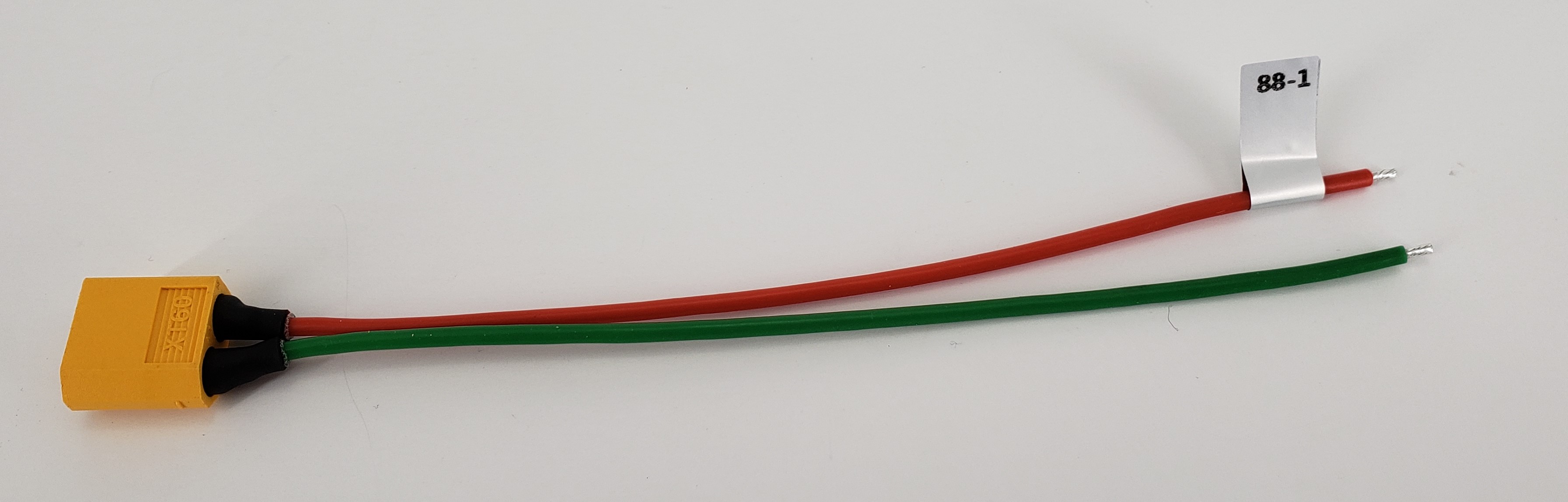
MCBL-00088
Description:
- Multi-Purpose XT60 Male to Pigtail Leads, 150mm
- Easily identifiable RED (+) and GREEN (-) cables
- Robust adhesive lined heatshrink for long-lasting protection of pin solder joints
Where used:
- Included in Stinger ESC for system power from battery
- Useful for ESC side or target side electronics when using an XT60 based battery
Details:
| Component | Details |
|---|---|
| Connector A | AMASS, XT60-M |
| Connector B | Pigtails, stripped and tinned 3.5mm |
| Length | 150mm (-1 variant) |
| Insulator | Silicon |
| Color | Red (+) and Green (-) |
| Gauge | 18 AWG |
| Weight | 7.3 grams (-1 variant) |
| A | B | ||
|---|---|---|---|
| + | + | + | RED |
| - | - | - | GREEN |
Pinout, Part Number, & Additional Specs: See Drawing Here. Contact ModalAI on the Forum for .DXF or .DWG formats of these drawings.
MCBL-00089
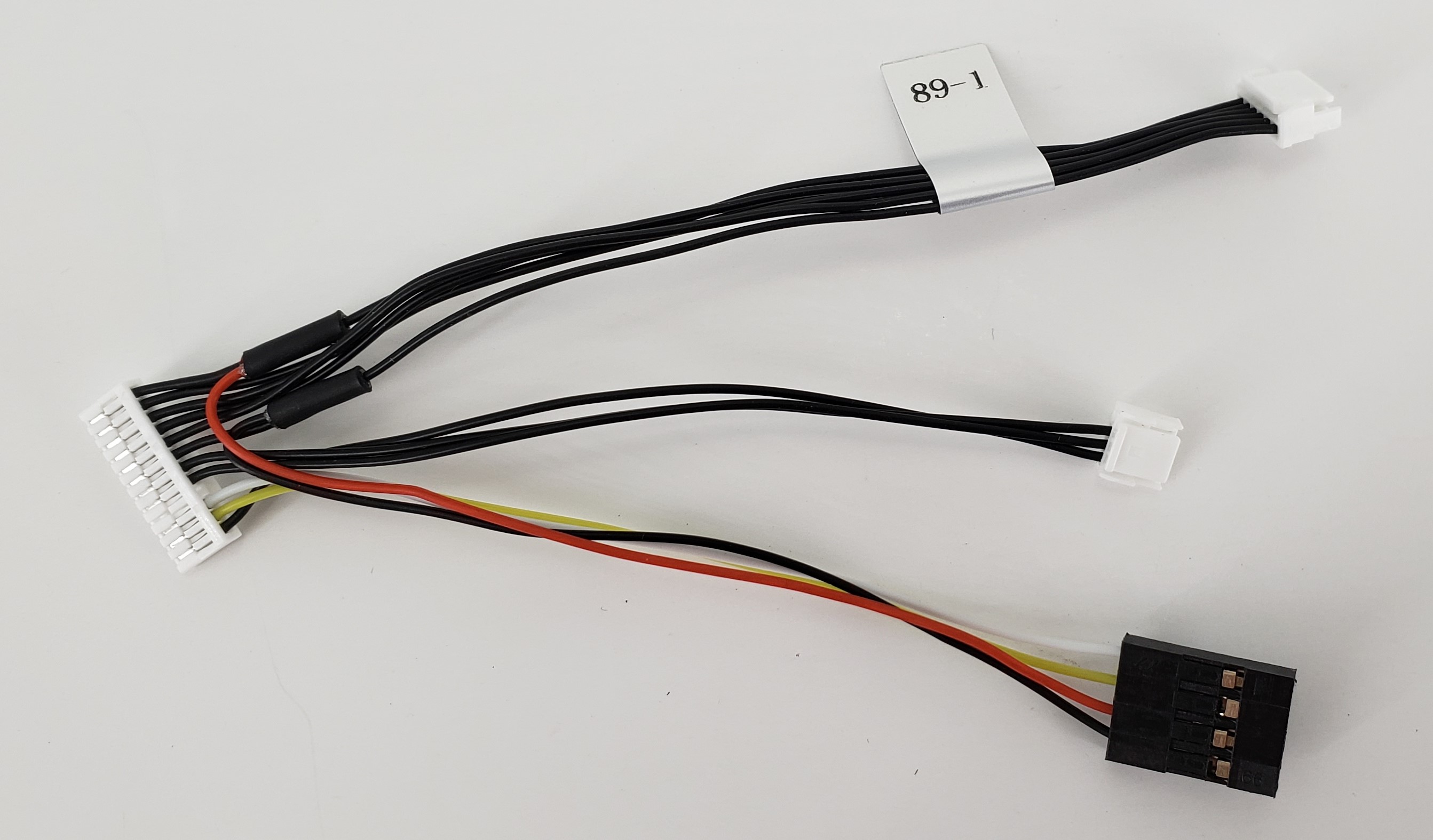
Description:
- Connects VOXL 2 Mini J19 to DroneCode Compliant GPS/Magnetometer unit + ModalAI Mini ESC (M0129) UART + an R/C unit 2W UART
- This cable provides power to the GNSS module and the R/C module at 5V (Mini ESC is powered from a battery)
- This cable excludes the 3.3V R/C voltage on J19 pin 9
- The 4-pin R/C port is pinned for a half-duplex UART (2 wire, TX & RX), but can alternatively be re-pinned into a 3-wire format H20 connector easily if needed. Follow the drawing .pdf link provided below to see the pinout details
- Note the R/C port power and GND cables are spliced in the opposite direction to allow the R/C connector to fold/flow leftward of the view shown in the image/cable drawings
Where Used:
- ModalAI Stinger Drone, with VOXL 2 Mini
- Any fully-featured VOXL 2 Mini drone that requires the full use of J19, i.e.: a “Full Breakout of J19”
Details:
| Component | Details |
|---|---|
| Connector A | JST 1.25mm GHR-12V-S, VOXL 2 Mini side, +3.3V signal levels |
| Connector B | JST 1.25mm GHR-06V-S, GNSS Module side, +3.3V signal levels |
| Connector C | JST 1.25mm GHR-04V-S, to Mini ESC (M0129), +3.3V signal levels |
| Connector D | Harwin 2.54mm M20-1060400 (Hobby format), R/C module, +3.3V signal levels |
| Length | 100mm (CONA-CONB), 80mm (CONA-CONC,COND) |
| Insulator | Silicone |
| Color | Black, Red, White, Yellow |
| Gauge | 28 AWG |
| Weight | 2.8 grams |
Pinout:
| A | VOXL 2 Mini | B | GNSS Module | C | M0129 ESC | D | R/C Module |
|---|---|---|---|---|---|---|---|
| 1 | 5V (Source) | 1 | 5V (Load) | 3 | R/C 5V (Red, Load) | ||
| 2 | UART_TX | 2 | UART_RX | ||||
| 3 | UART_RX | 3 | UART_TX | ||||
| 4 | MAG_I2C_SCL | 4 | SCL | ||||
| 5 | MAG_I2C_SDA | 5 | SDA | ||||
| 6 | GND | 6 | GND | 4 | GND (Black) | ||
| 7 | ESC_UART_TX | 2 | R/C_RX | ||||
| 8 | ESC_UART_RX | 3 | R/C_TX | ||||
| 10 | RC_UART_TX | 1 | R/C_RX (White) | ||||
| 11 | RC_UART_RX | 2 | R/C_TX (Yellow) | ||||
| 12 | GND | 4 | ESC GND |
Pinout, Part Number, & Additional Specs: See Drawing Here Contact ModalAI on the Forum for .DXF or .DWG formats of this drawing.
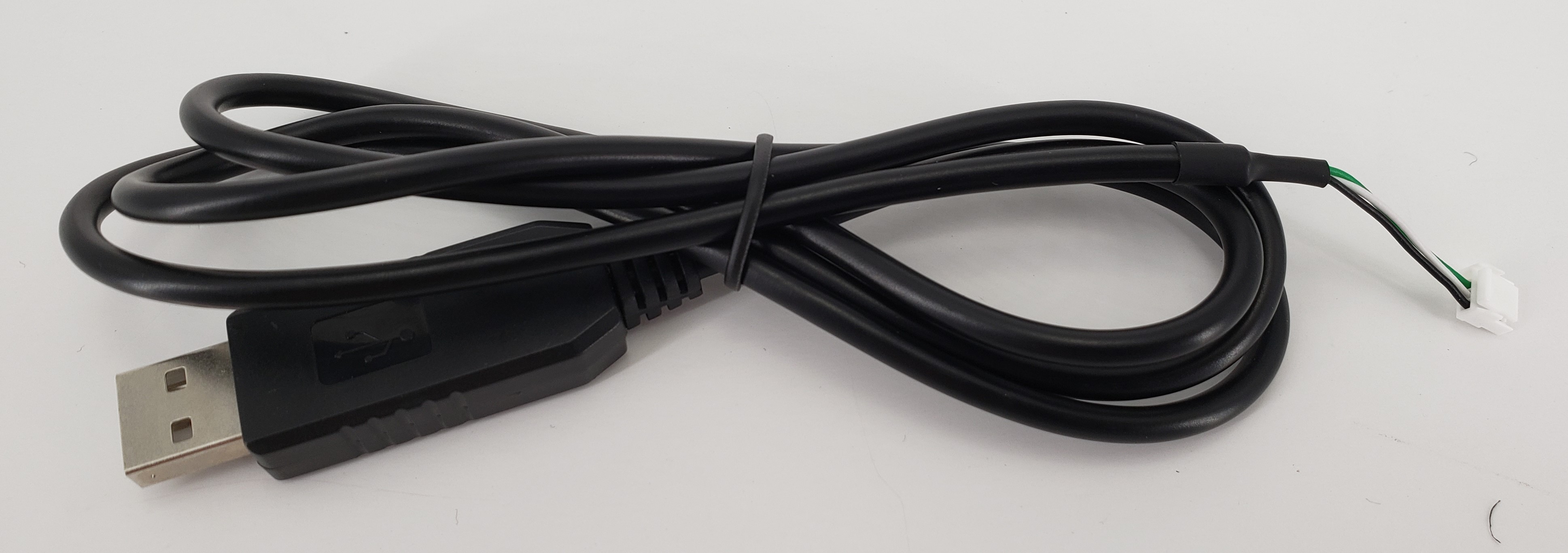
MCBL-00090
Description:
- Voxl Ecosystem Format Serial Debug Console Cable to Host PC USB Port
- This cable converts ModalAI “standard” 4-pin JST SRSS Debug UART port to USB using embedded FTDI adapter
Where Used:
- All over ModalAI’s Ecosystem of Debug boards and plug-in boards, such as:
- M0144 B-Quad (J6), M0130 New 4G Modem (J6, DNI’d), M0104 VOXL 2 MINI (J4), M0048 Microhard Modem (J2), M0030 4G Modem V2 (J2)
- Serial Debug Port Settings at Host (115200 “8N1”):
- 115,200 Baud
- 8 bits
- No Parity/Flow Control
- 1 stop bit
Details:
| Component | Details |
|---|---|
| Connector A | USB STD-A Plug |
| Connector B | JST 1.0mm SHR-04V-S, +3.3V signal levels |
| Length | 1 Meter |
| Insulator | PVC |
| Color | Black |
| Gauge | 28 AWG |
| Weight | 27.4 grams |
Pinout:
| A | PC/USB | B | Target Board with Serial Debug Port |
|---|---|---|---|
| 1 | VBUS | 1 | Not Connected |
| 2 | D- | 2 | UART_RX, 3.3V Signal Levels (Green Wire = FTDI TX) |
| 3 | D+ | 3 | UART_TX, 3.3V Signal Levels (White Wire = FTDI RX) |
| 4 | DGND | 4 | DGND |
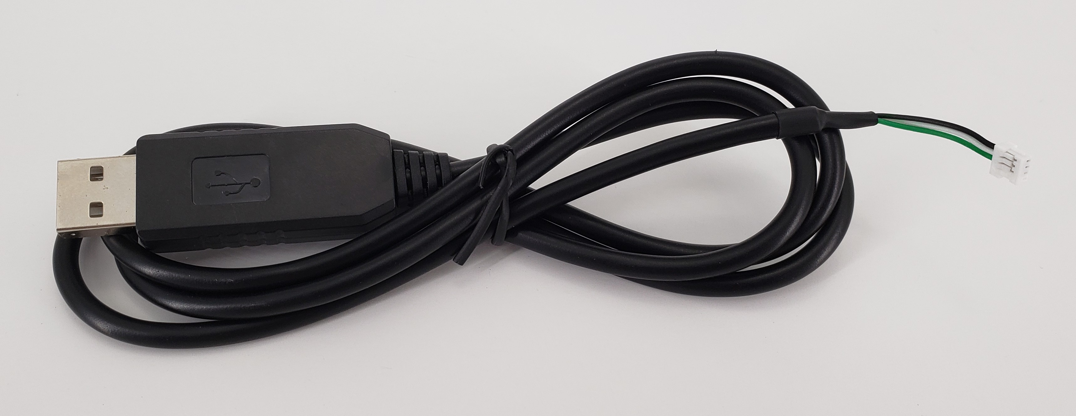
MCBL-00091
Description:
- VOXL 2 ESC UART (4-Pin JST-GH format) Serial Port Cable to Host PC USB Port (FTDI)
- ModalAI 3.3V Signal Level UART Port to USB using embedded FTDI adapter
Where Used:
- All over ModalAI’s VOXL 2 Ecosystem UARTs and expansion boards and plug-in boards
- Specifically pinned for ESC Tools Support with direct plug into M0129 ESC and future ESCs (no adapter required)
- With ModalAI’s M0163 JST Flexi-Adapter (INSTRUCTIONS/Images AND MORE INFO COMING SOON!!!), easy re-configuration for:
- Hardware In the Loop (HWIL/HIL) ESC UART to M0054/M0154 (VOXL 2)
- Any Dronecode Compliant UART port (6-pin JST GH) to USB serial (Not just ModalAI hardware)
- Any UART port (4-pin JST GH) to USB serial
Details:
| Component | Details |
|---|---|
| Connector A | USB STD-A Plug |
| Connector B | JST 1.25mm GHR-04V-S, +3.3V signal levels |
| Length | 1 Meter |
| Insulator | PVC |
| Color | Black |
| Gauge | 28 AWG |
| Weight | 26.4 grams |
Pinout:
| A | PC/USB | B | Target Board with Serial Debug Port |
|---|---|---|---|
| 1 | VBUS | 1 | Not Connected |
| 2 | D- | 2 | UART_RX, 3.3V Signal Levels (Green Wire = FTDI TX) |
| 3 | D+ | 3 | UART_TX, 3.3V Signal Levels (White Wire = FTDI RX) |
| 4 | DGND | 4 | DGND |
MCBL-00092
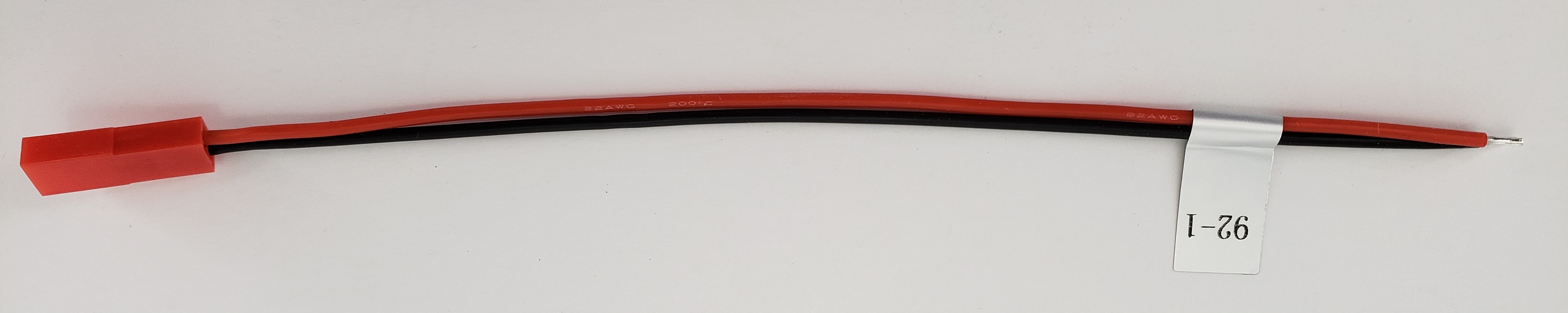
Description:
- JST RCY Receptacle Cable Assembly RED/BLACK, 150mm, Pigtails
Where Used:
- General Purpose Use for Power Delivery using popular JST RCY Family Connector Series
Details:
| Component | Details |
|---|---|
| Connector A | JST RCY Receptacle, SYR-02T |
| Connector B | Pigtails, Stripped and Tinned |
| Length | 150 mm |
| Insulator | Silicone |
| Color | Red/Black |
| Gauge | 22 AWG |
| Weight | 2.1 grams |
Pinout:
| A | B | ||
|---|---|---|---|
| 1 | - | - | BLACK |
| 2 | + | + | RED |
Pinout, Part Number, & Additional Specs: See Drawing Here Contact ModalAI on the Forum for .DXF or .DWG formats of this drawing.
MCBL-00093
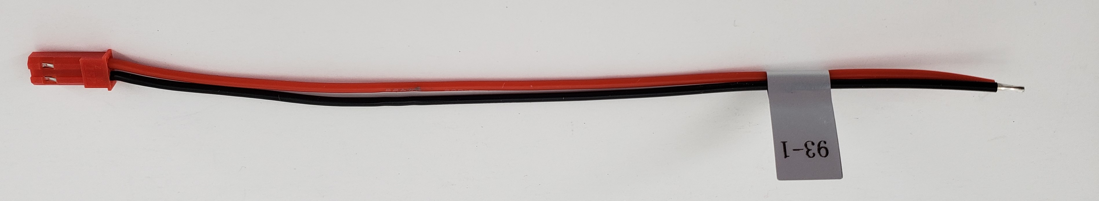
Description:
- JST RCY Plug Cable Assembly RED/BLACK, 150mm, Pigtails
Where Used:
- General Purpose Use for Power Delivery using popular JST RCY Family Connector Series
Details:
| Component | Details |
|---|---|
| Connector A | JST RCY Plug, SYP-02T |
| Connector B | Pigtails, Stripped and Tinned |
| Length | 150 mm |
| Insulator | Silicone |
| Color | Red/Black |
| Gauge | 22 AWG |
| Weight | 1.9 grams |
Pinout:
| A | B | ||
|---|---|---|---|
| 1 | - | - | BLACK |
| 2 | + | + | RED |
Pinout, Part Number, & Additional Specs: See Drawing Here Contact ModalAI on the Forum for .DXF or .DWG formats of this drawing.
MCBL-00094
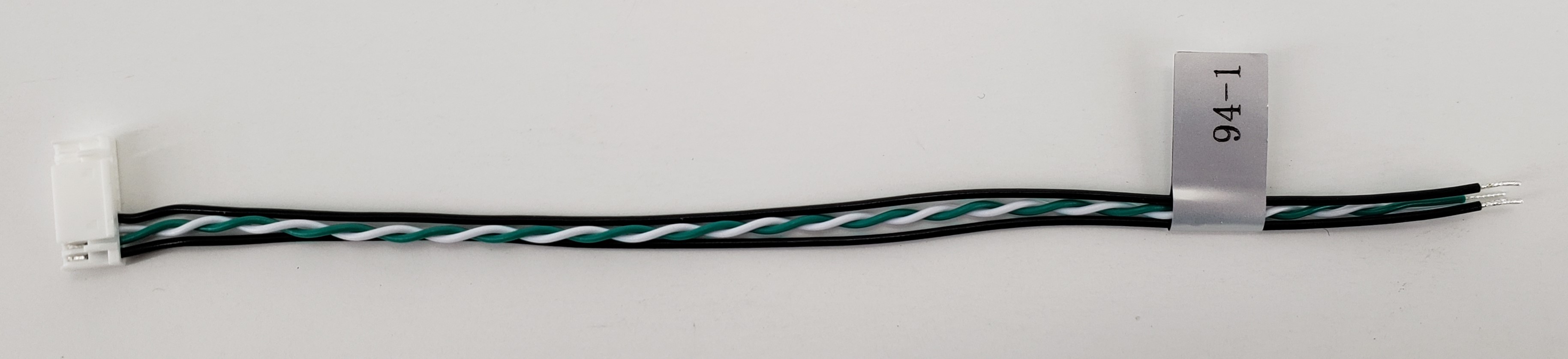
Description:
- USB3 10-pin JST cable to USB2 Pigtails
Where Used:
- Any USB2 downstream port that needs to connect to ModalAI’s 10-pin USB3 Format
- Ideal for connecting custom hardware to the VOXL 2 Mini platform or M0090 5G Modem designs
Details:
| Component | Details |
|---|---|
| Connector A | 10POS 1.25mm JST, GHR-10V-S |
| Connector B | Pigtails |
| Length | 150mm |
| Insulator | PVC |
| Color | Black, White/Green TP |
| Gauge | 26AWG VBUS/GND, 28AWG Twisted Pair Signals |
| Weight | 1.3 grams |
Pinout:
| A | B | Pigtails | |
|---|---|---|---|
| 1 | VBUS (Source) | 1 | VBUS (Load) |
| 2 | USB_D- | 2 | D- |
| 3 | USB_D+ | 3 | D+ |
| 4 | GND | 4 | GND |
| 5 | NC | ||
| 6 | NC | ||
| 7 | NC | ||
| 8 | NC | ||
| 9 | NC | ||
| 10 | NC |
Pinout, Part Number, & Additional Specs: See Drawing Here Contact ModalAI on the Forum for .DXF or .DWG formats of this drawing.
MCBL-00095
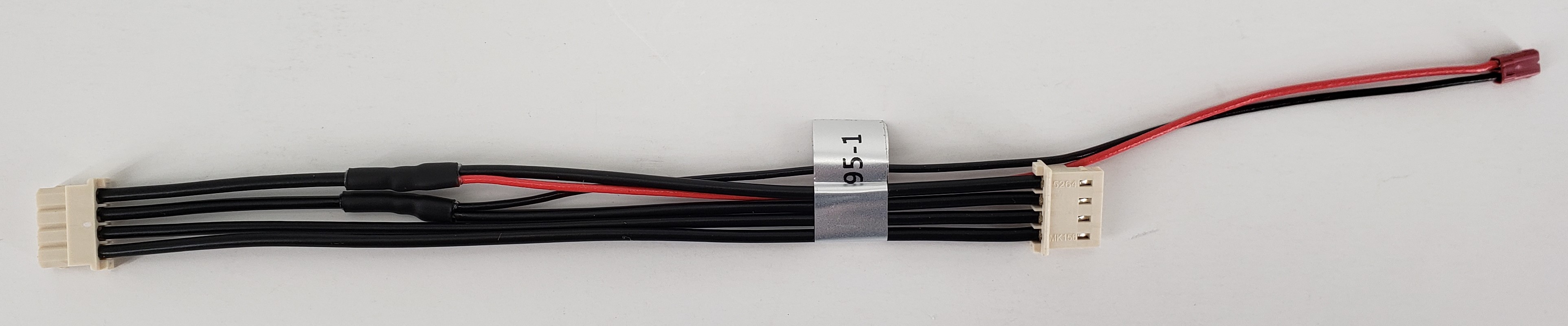
Description:
- VOXL-PM-Y for Legacy ToF M0169 Adapter CCA from one Power Module, with the I2C bus for power monitoring going to VOXL 2
Where Used:
- M0169 with VOXL 2
Details:
| Component | Details |
|---|---|
| Connector A | Molex, 0050375043 (Power Module side, 4 wires) |
| Connector B | Molex, 0050375043 (VOXL side, 4 wires) |
| Connector C | JST, SFHR-02V-R (connects to M0169 CCA, 2 wires) |
| Length | 125mm (A - B), 190mm (A - C) |
| Insulator | PVC (flexible) |
| Color | Black and Red |
| Gauge | 20AWG (A-to-B)/ 24AWG (A-to-C) |
| Weight | 5.9 grams |
Pinout:
| A | VOXL 2 PM | B | VOXL 2 | C | M0169 Legacy ToF CCA |
|---|---|---|---|---|---|
| 1 | 5V DC (Source) | 1 | 5V DC (Load) | 1 | 5V DC (Load) |
| 2 | GND | 2 | GND | 2 | GND |
| 3 | SCL | 3 | PM_I2C3_SCL_5V | - | - |
| 4 | SDA | 4 | PM_I2C3_SDA_5V | - | - |
Pinout, Part Number, & Additional Specs: See Drawing Here Contact ModalAI on the Forum for .DXF or .DWG formats of this drawing.
MCBL-00098
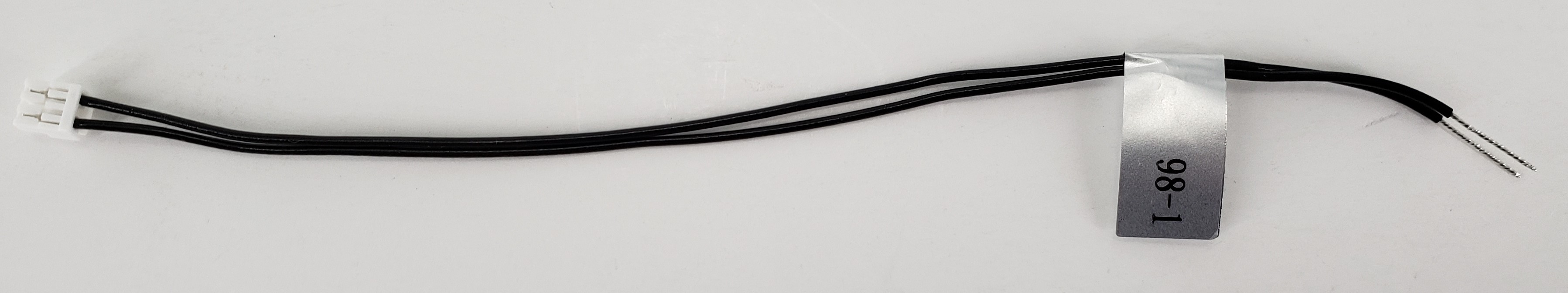
Description:
- Cable providing a partial (sub-populated) JST GH 3-pin breakout, with just pins 1 & 3.
Where Used:
- Great for FCv1 connections with a 3-pin JST GH connector for Power and GND tap-offs
- Note: pigtail side is tinned for ~10mm making it easy to install JST SSHL-002T-P0.2 pins if needed
- Great item to have for making your own cables!!
Details:
| Component | Details |
|---|---|
| Connector A | JST 1.25mm GHR-03V-S |
| Connector B | None: Pigtails |
| Length | 150mm (10mm pigtails) |
| Insulator | PVC (flexible) |
| Color | Black |
| Gauge | 26 AWG |
| Weight | 0.8 grams |
Pinout:
| A | |||
|---|---|---|---|
| 1 | 1 | (pigtail) | |
| 2 | - | ||
| 3 | 3 | (pigtail) |
Pinout, Part Number, & Additional Specs: See Drawing Here Contact ModalAI on the Forum for .DXF or .DWG formats of this drawing.
MCBL-00099
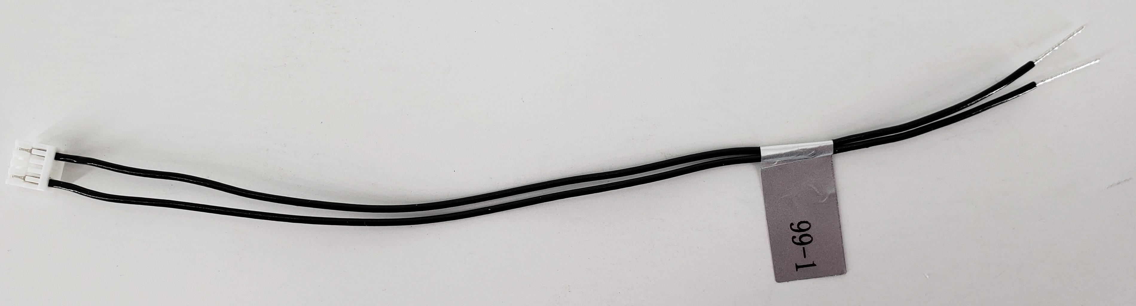
Description:
- Cable providing a partial (sub-populated) JST GH 4-pin breakout, with just pins 1 & 4.
Where Used:
- Great for FCv1/FCv2 connections with a 4-pin JST GH connector for Power and GND tap-offs
- Note: pigtail side is tinned for ~10mm making it easy to install JST SSHL-002T-P0.2 pins if needed
- Great item to have for making your own cables!!
Details:
| Component | Details |
|---|---|
| Connector A | JST 1.25mm GHR-04V-S |
| Connector B | None: Pigtails |
| Length | 150mm (10mm pigtails) |
| Insulator | PVC (flexible) |
| Color | Black |
| Gauge | 26 AWG |
| Weight | 0.8 grams |
Pinout:
| A | |||
|---|---|---|---|
| 1 | 1 | (pigtail) | |
| 2 | - | ||
| 3 | - | ||
| 4 | 4 | (pigtail) |
Pinout, Part Number, & Additional Specs: See Drawing Here Contact ModalAI on the Forum for .DXF or .DWG formats of this drawing.
MCBL-00100
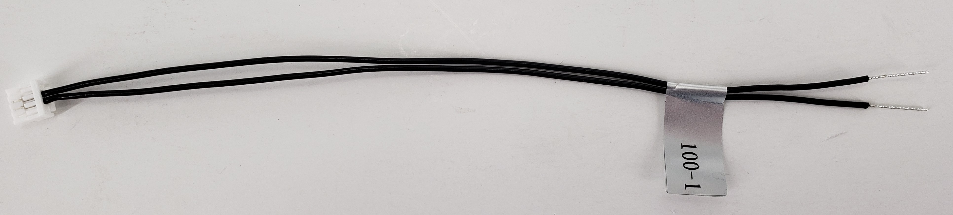
Description:
- Cable providing a partial (sub-populated) JST GH 4-pin breakout, with just pins 2 & 3.
Where Used:
- Great for FCv1/FCv2 connections with a 4-pin JST GH connector for UART only tap-offs
- Note: pigtail side is tinned for ~10mm making it easy to install JST SSHL-002T-P0.2 pins if needed
- Great item to have for making your own cables!!
Details:
| Component | Details |
|---|---|
| Connector A | JST 1.25mm GHR-04V-S |
| Connector B | None: Pigtails |
| Length | 150mm (10mm pigtails) |
| Insulator | PVC (flexible) |
| Color | Black |
| Gauge | 26 AWG |
| Weight | 0.8 grams |
Pinout:
| A | |||
|---|---|---|---|
| 1 | - | ||
| 2 | 2 | (pigtail) | |
| 3 | 3 | (pigtail) | |
| 4 | - |
Pinout, Part Number, & Additional Specs: See Drawing Here Contact ModalAI on the Forum for .DXF or .DWG formats of this drawing.
MCBL-00103
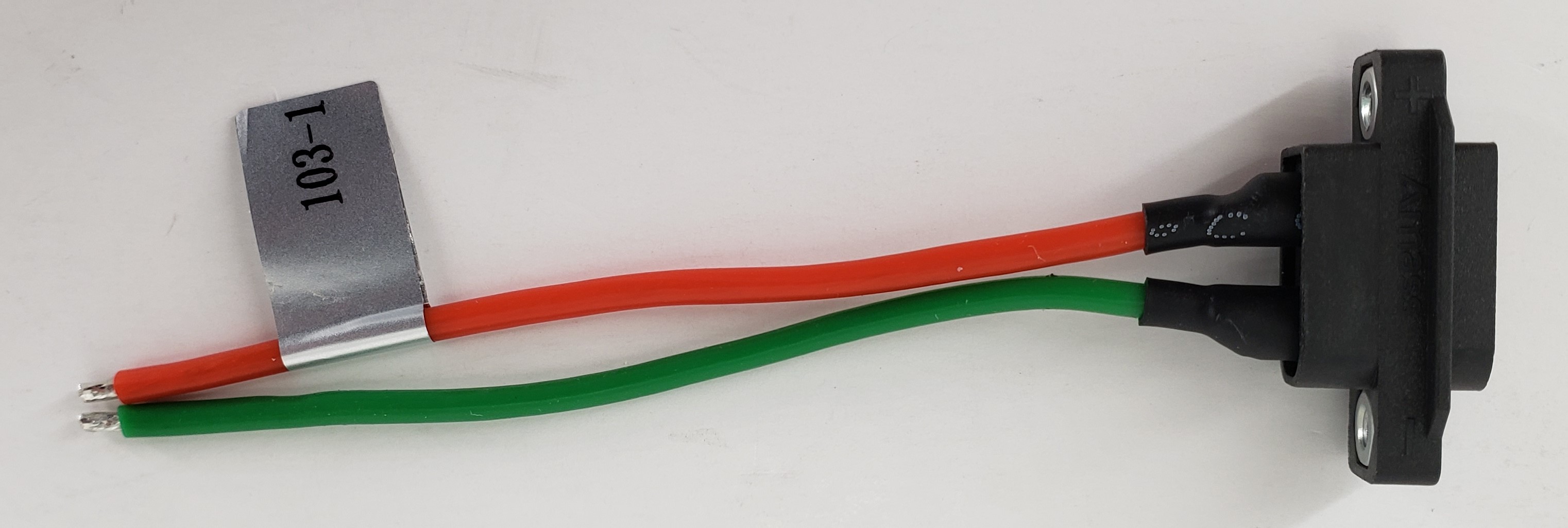
Description:
- Multi-Purpose XT60 Bulkhead Male to Pigtail Leads, 80mm
- Easily identifiable RED (+) and GREEN (-) cables
- Robust adhesive lined heatshrink for long-lasting protection of pin solder joints
Where used:
- Included in Stinger ESC for system power from battery
- Useful for ESC side or target side electronics when using an XT60 based battery
Details:
| Component | Details |
|---|---|
| Connector A | AMASS, XT60EW-M |
| Connector B | Pigtails, stripped and tinned 3.5mm |
| Length | 80mm (-1 variant) |
| Insulator | Silicon |
| Color | Red (+) and Green (-) |
| Gauge | 18 AWG |
| Weight | 5.9 grams (-1 variant) |
| A | B | ||
|---|---|---|---|
| + | + | + | RED |
| - | - | - | GREEN |
Pinout, Part Number, & Additional Specs: See Drawing Here. Contact ModalAI on the Forum for .DXF or .DWG formats of these drawings.
MCBL-00104
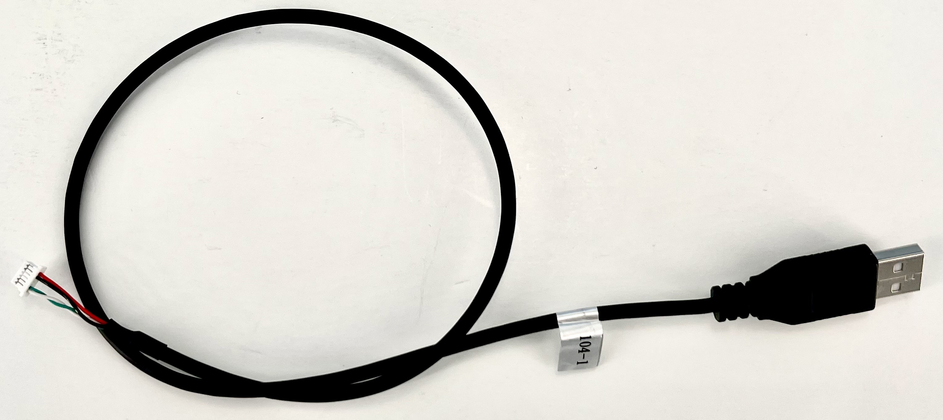
Description:
- 6-pin JST SH to USB Type A
Where Used:
- USB Host for configuring a Boson Sensor
Details:
| Component | Details |
|---|---|
| Connector A | USB, Type A Male |
| Connector B | JST, SHR-06V-S-B, 1.0mm Housing (with Protrusions), 6-POS |
| Length | 500mm |
| Insulator | PVC |
| Color | Black, White/Green TP, Red |
| Gauge | 26 AWG, 28AWG Twisted Pair |
| Weight | 16.8 grams |
Pinout:
| A | Signal | B | Signal |
|---|---|---|---|
| 1 | VBUS (Source) | 1 | VBUS (Load) |
| 2 | D- | 6 | D- |
| 3 | D+ | 5 | D+ |
| 4 | GND | 2 | GND |
Pinout, Part Number, & Additional Specs: See Drawing Here Contact ModalAI on the Forum for .DXF or .DWG formats of this drawing.
MCBL-00105
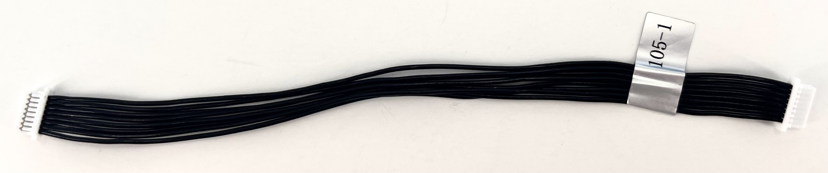
Description:
- 8pin-JST-to-8pin-JST cable (straight through 1:1)
Where Used:
- Note there are two variants, -1 and -2
- “-1” 150mm.
- “-2” is a shorter length, 100mm, used on Starling 2 drones
Details:
| Component | Details |
|---|---|
| Connector A | JST, SHR-08V-S-B, 1.00mm Housing (with Protrusions), 8-POS |
| Connector B | JST, SHR-08V-S-B, 1.00mm Housing (with Protrusions), 8-POS |
| Length | 150mm (-1 variant), 100mm (-2 variant) |
| Insulator | PVC |
| Color | Black |
| Gauge | 26 AWG |
| Weight | 2.9 grams (-1 variant), 2.0 grams (-2 variant) |
Pinout:
| A | B | ||
|---|---|---|---|
| 1 | Pin1 | 1 | Pin1 |
| 2 | Pin2 | 2 | Pin2 |
| 3 | Pin3 | 3 | Pin3 |
| 4 | Pin4 | 4 | Pin4 |
| 5 | Pin5 | 5 | Pin5 |
| 6 | Pin6 | 6 | Pin6 |
| 7 | Pin7 | 7 | Pin7 |
| 8 | Pin8 | 8 | Pin8 |
Pinout, Part Number, & Additional Specs: See -1 Drawing Here, See -2 Drawing Here Contact ModalAI on the Forum for .DXF or .DWG formats of these drawings.
MCBL-00106
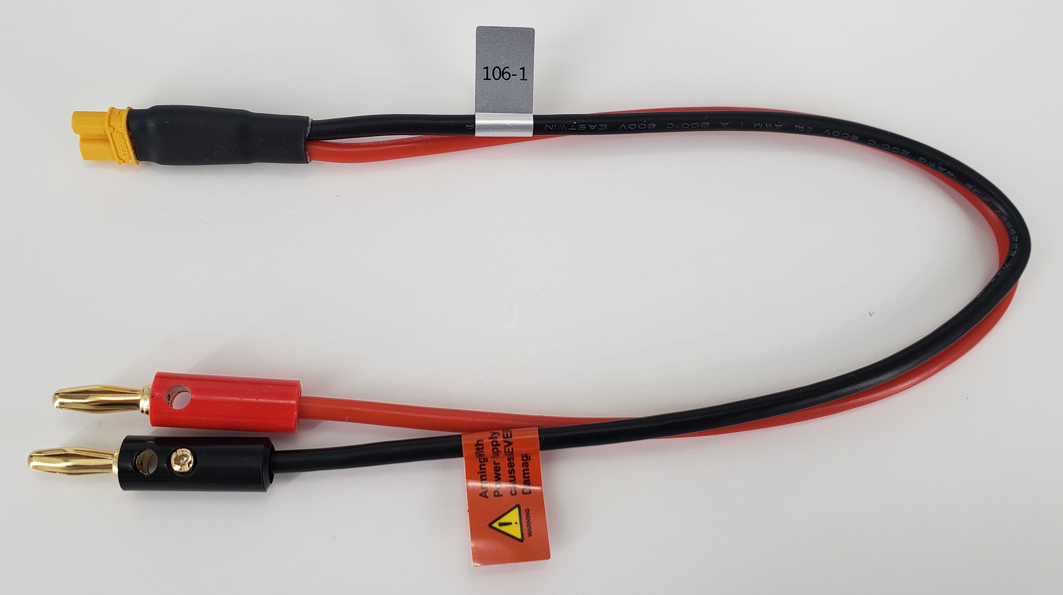
Description:
- Multi-Purpose XT30U-F to Banana Jacks, 300mm
- Easily identifiable RED (+) and BLACK (-) cables
- Robust adhesive lined heatshrink for long-lasting protection of pin solder joints
- Easily removable set-screw based Banana Plugs to expose stripped/tinned cable for other uses
Where used:
- Useful for VOXL 2 Development within a Pre-Built Drone without needing a battery by using a power supply
- CAUTION: NEVER ARM THE DRONE USING A POWER SUPPLY. THE ELECTRONICS WILL BE DAMAGED AND VOID ALL WARRANTIES
Details:
| Component | Details |
|---|---|
| Connector A | AMASS, XT30U-F |
| Connector B | Banana Plugs, 4mm, Gold Plated, set-screw secured^ |
| Length | 300mm |
| Insulator | Silicon |
| Color | Red (+) and Black (-) |
| Gauge | 14 AWG |
| Weight | 25 grams |
| A | B | ||
|---|---|---|---|
| + | + | + | RED |
| - | - | - | BLACK |
^ Note: If desired, the set-screw in the side of the banana plug can be loosened to expose the bare stripped and tinned cable inside for soldering to your own format as desired. Because of this however, it may be possible for the screw to come loose over time. If intermittent power issues are suspected during normal operations, be sure to tighten this screw firmly before use. Here is an example of the cables inside the set-screw plugs:
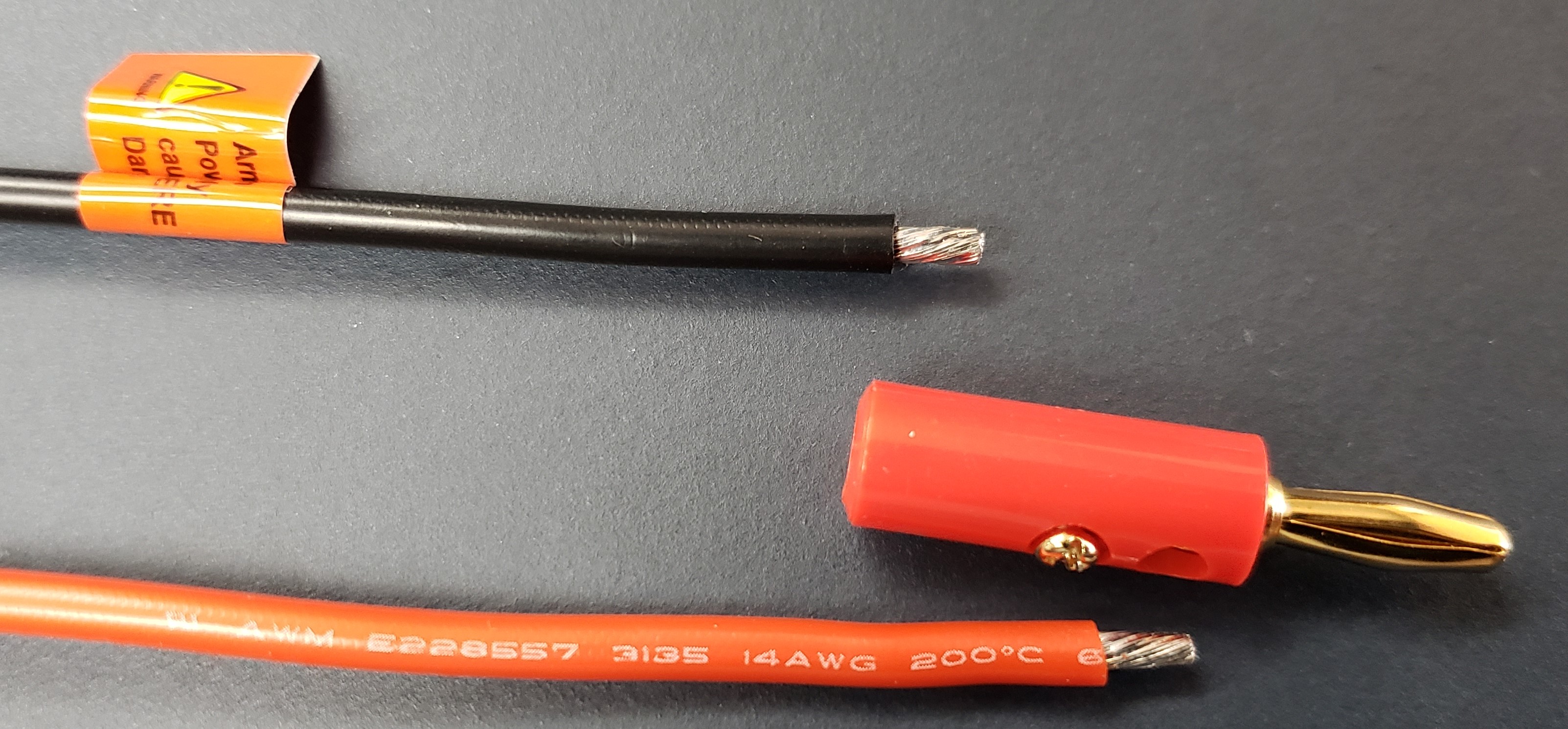
Pinout, Part Number, & Additional Specs: See Drawing Here. Contact ModalAI on the Forum for .DXF or .DWG formats of these drawings.
MCBL-00107
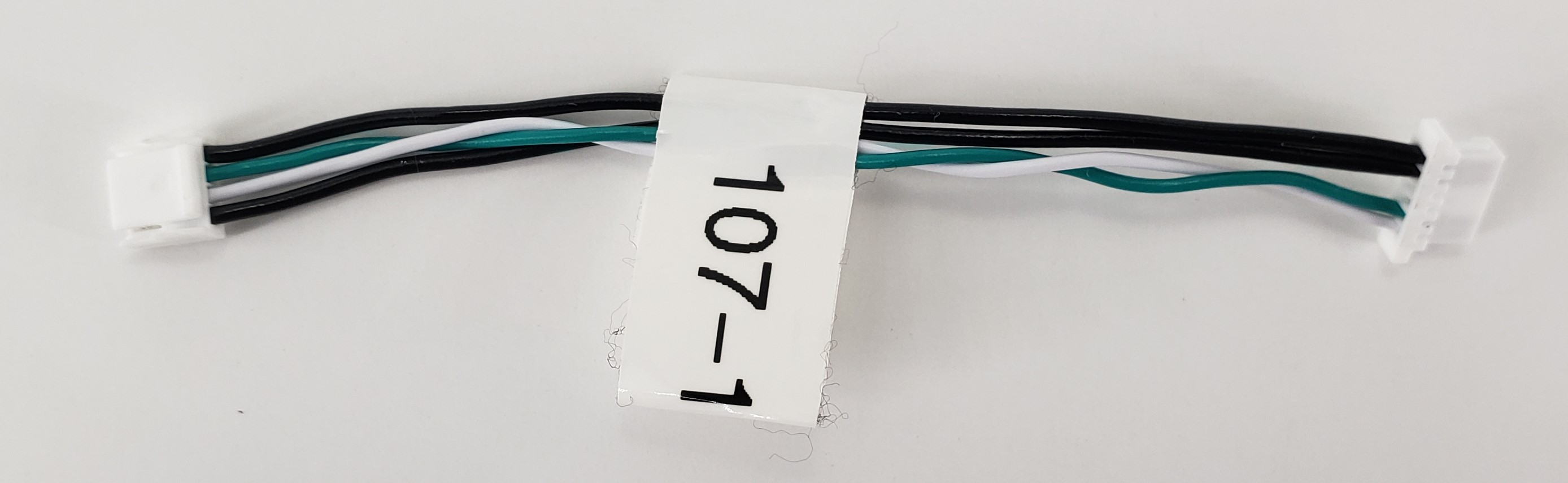
Description:
- VOXL 2 4-pin JST USB to Boson RHP-BOS-VPC3-IF 6-JST Cable providing a direct connection from ModalAI’s USB2 ports (M0090, M0130) to a FLIR Boson that uses the RHP-BOS-VPC3-IF “backpack”
- Note: Only picks up the USB2 bus, For the 10-pin version, see MCBL-00072 Where Used:
VOXL 2 Modem or USB expansion boards Sierra 4G Plug-ins (M0130), 5G Plug-ins (M0090)
Details:
| Component | Details |
|---|---|
| Connector A | 4 POS 1.25mm JST, GHR-04V-S |
| Connector B | 6 POS 1.00mm JST, SHR-06V-S-B, Backpack side |
| Length | 70mm |
| Insulator | PVC |
| Color | Black (VBUS/GND), White/Green Twisted Pair D+/D- |
| Gauge | Black 26 AWG, White/Green TP 28AWG |
| Weight | 0.9 grams |
Pinout:
| A | B | ||
|---|---|---|---|
| 1 | VBUS (Source) | 1 | 5VDC (Load) |
| 2 | USB_D- | 6 | Boson D- |
| 3 | USB_D+ | 5 | Boson D+ |
| 4 | GND | 2 | GND |
Pinout, Part Number, & Additional Specs: See Drawing Here Contact ModalAI on the Forum for .DXF or .DWG formats of this drawing.
MCBL-00109
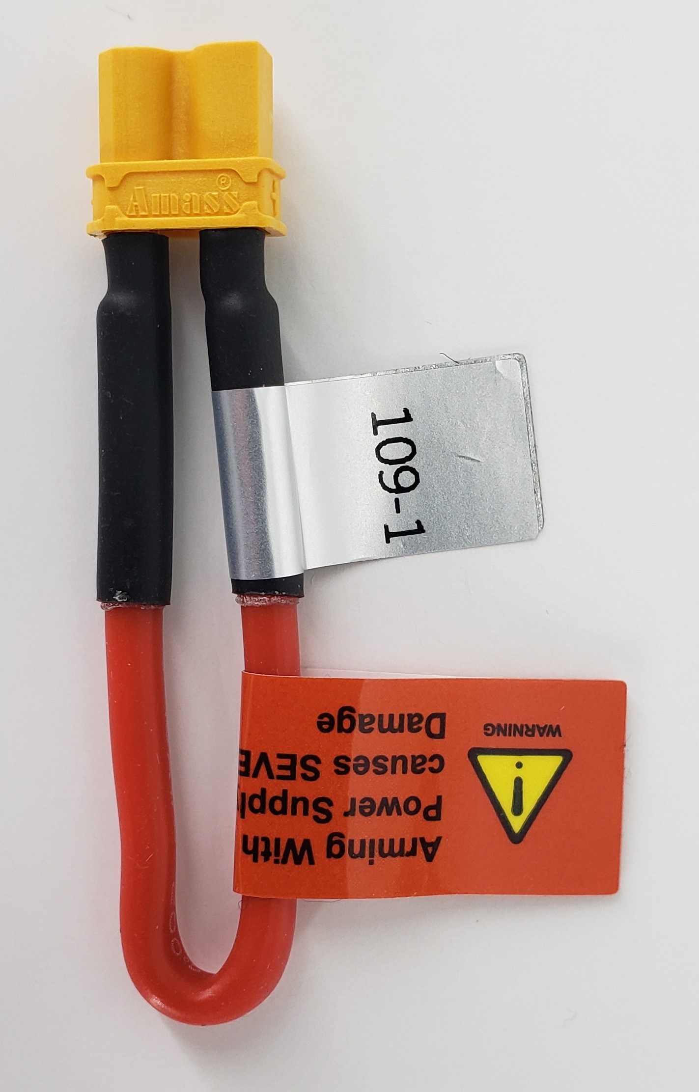
Description:
- XT30U-F Power Jumper, 80mm
- Robust adhesive lined heatshrink for long-lasting protection of pin solder joints
Where used:
- Useful for a Pre-Built Drone like STARLING V2 to bypass the second battery when using MCBL-00106 with a power supply
- CAUTION: NEVER ARM THE DRONE USING A POWER SUPPLY. THE ELECTRONICS WILL BE DAMAGED AND VOID ALL WARRANTIES
Details:
| Component | Details |
|---|---|
| Connector A | AMASS, XT30U-F |
| Length | 80mm |
| Insulator | Silicon |
| Color | Red (+) and (-) |
| Gauge | 16 AWG |
| Weight | 2.7 grams |
| A | A | ||
|---|---|---|---|
| + | + | - | - (RED) |
Pinout, Part Number, & Additional Specs: See Drawing Here. Contact ModalAI on the Forum for .DXF or .DWG formats of these drawings.
MCBL-00110
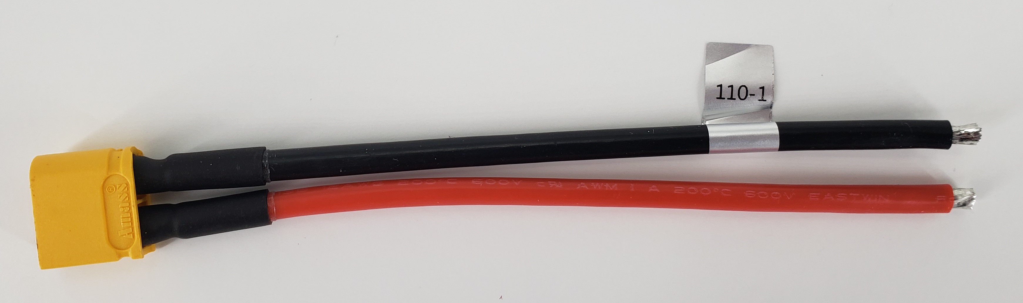
Description:
- Multi-Purpose XT60 Male to Pigtail Leads, 120mm
- Easily identifiable RED (+) and BLACK (-) cables
- Robust adhesive lined heatshrink for long-lasting protection of pin solder joints
Where used:
- Useful for ESC side or target side electronics when using an XT60 based battery
Details:
| Component | Details |
|---|---|
| Connector A | AMASS, XT60-M |
| Connector B | Pigtails, stripped and tinned 4mm |
| Length | 120mm |
| Insulator | Silicon |
| Color | Red (+) and Black (-) |
| Gauge | 12 AWG |
| Weight | 12.9 grams |
| A | B | ||
|---|---|---|---|
| + | + | + | RED |
| - | - | - | BLACK |
Pinout, Part Number, & Additional Specs: See Drawing Here. Contact ModalAI on the Forum for .DXF or .DWG formats of these drawings.
MCBL-00111
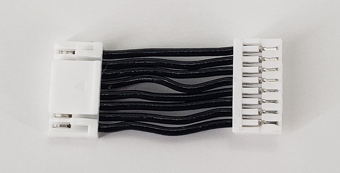
Description:
- 8pin-JST-to-8pin-JST cable (straight through 1:1) Short Jumper Cable
Where Used:
- VOXL Add-On boards to stacked boards where the 8-pin SPI port (or other) is desired to connect very close to VOXL 2 or Mini
- Great item to have for making your own cables!!
- Note this has no label on it due to its size.
Details:
| Component | Details |
|---|---|
| Connector A | JST, GHR-08V-S |
| Connector B | JST, GHR-08V-S |
| Length | 15mm |
| Insulator | PVC (flexible) |
| Color | Black |
| Gauge | 26 AWG |
| Weight | 0.8 grams |
Pinout:
| A | B | ||
|---|---|---|---|
| 1 | Pin1 | 1 | Pin1 |
| 2 | Pin2 | 2 | Pin2 |
| 3 | Pin3 | 3 | Pin3 |
| 4 | Pin4 | 4 | Pin4 |
| 5 | Pin5 | 5 | Pin5 |
| 6 | Pin6 | 6 | Pin6 |
| 7 | Pin7 | 7 | Pin7 |
| 8 | Pin8 | 8 | Pin8 |
Pinout, Part Number, & Additional Specs: See Drawing Here Contact ModalAI on the Forum for .DXF or .DWG formats of these drawings.
MCBL-00112
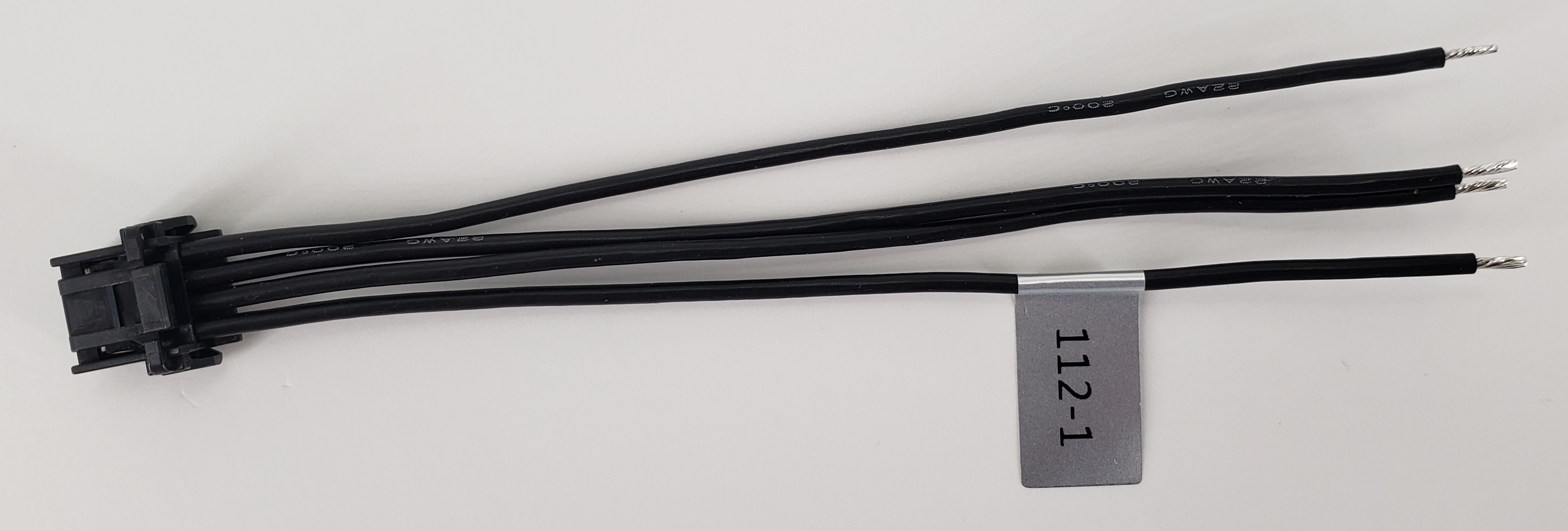
Description:
- Cable providing a full 4-pin breakout of the 4-pin MicroOne connector used on VOXL 2 Mini
Where Used:
- Built into MDK-M0041-4-00 power module assemblies
- Great for custom power module or ESC power pad soldering to VOXL 2 Mini systems
- Pigtail side is tinned for ~5mm making it easy to install on solder pads
- Great item to have for making your own cables!!
Details:
| Component | Details |
|---|---|
| Connector A | Molex 2.0mm MicroOne 2059792041 |
| Connector B | None: Pigtails |
| Length | 100mm (5mm pigtails) |
| Insulator | Silcon |
| Color | Black |
| Gauge | 22 AWG |
| Weight | 2.8 grams |
Pinout:
| A | B | ||
|---|---|---|---|
| 1 | 1 | (pigtail) | |
| 2 | 2 | (pigtail) | |
| 3 | 3 | (pigtail) | |
| 4 | 4 | (pigtail) |
Pinout, Part Number, & Additional Specs: See Drawing Here Contact ModalAI on the Forum for .DXF or .DWG formats of this drawing.
MCBL-00113
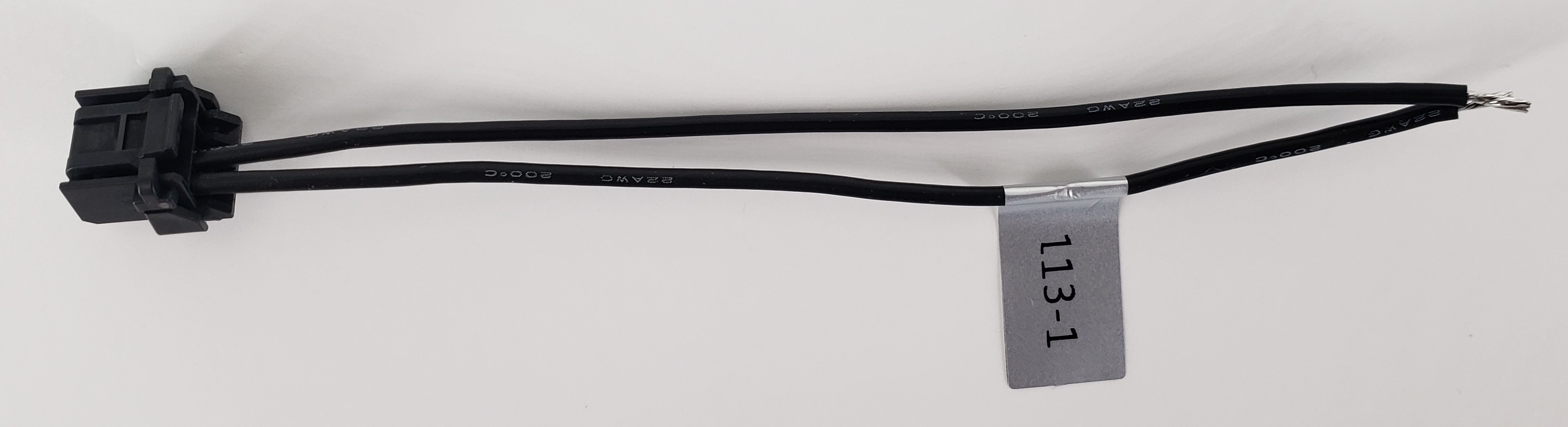
Description:
- Cable providing a sub-pop (partial) 2-pin breakout of the 4-pin MicroOne connector used on VOXL 2 Mini
- Power Leads Only (1&2), no I2C bus cables (3&4)
Where Used:
- Built into ESC assemblies for VOXL 2 Mini
- Great for custom power module or ESC power pad soldering to VOXL 2 Mini systems
- Pigtail side is tinned for ~5mm making it easy to install on solder pads
- Great item to have for making your own cables!!
Details:
| Component | Details |
|---|---|
| Connector A | Molex 2.0mm MicroOne 2059792041 |
| Connector B | None: Pigtails |
| Length | 100mm (5mm pigtails) |
| Insulator | Silcon |
| Color | Black |
| Gauge | 22 AWG |
| Weight | 1.6 grams |
Pinout:
| A | B | ||
|---|---|---|---|
| 1 | 1 | (pigtail) | |
| 2 | 2 | (pigtail) | |
| 3 | 3 | - | |
| 4 | 4 | - |
Pinout, Part Number, & Additional Specs: See Drawing Here Contact ModalAI on the Forum for .DXF or .DWG formats of this drawing.
MCBL-00114
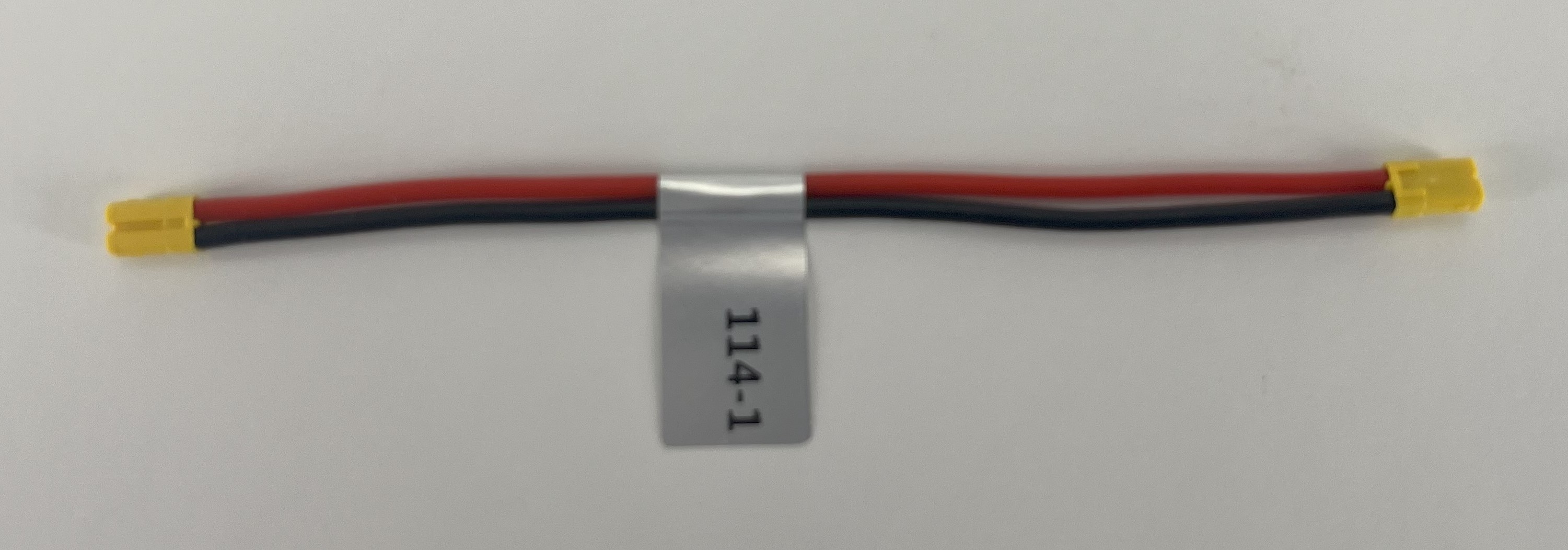
Description:
- ModalAI Yellow 2S-6S VBAT Format End-to-End Extension Cable
Where Used:
- Embedded within ESC and VTX/VRX Assemblies
- Useful for general purpose JST eSFH connector hookups, with the yellow format
- Note: Red version are ModalAI’s 5V format and Black/Grey are ModalAI’s 1S VBAT (3.8V) format
Details:
| Component | Details |
|---|---|
| Connector A & B | JST, SFHR-02V-L, 1.8mm Housing, 2-POS |
| Length | 80mm |
| Insulator | Silicone |
| Color | Red/Black |
| Gauge | 22 AWG |
| Weight | 1.0 gram |
Pinout:
| A | Signal | B | Signal |
|---|---|---|---|
| 1 | + (Red) | 1 | + |
| 2 | - (Black) | 2 | - |
Pinout, Part Number, & Additional Specs: See Drawing Here Contact ModalAI on the Forum for .DXF or .DWG formats of this drawing.
MCBL-00115
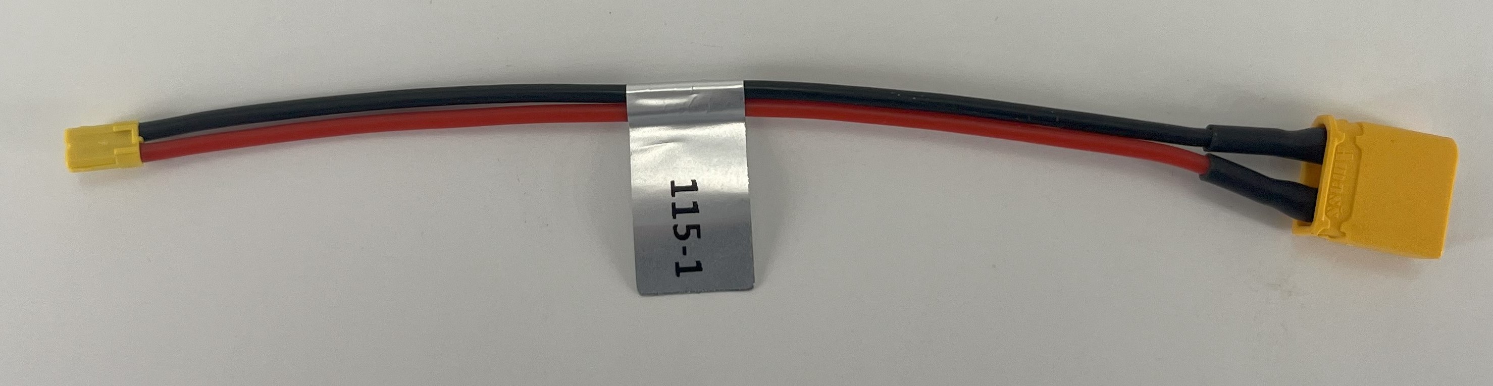
Description:
- ModalAI Yellow 2S-6S VBAT Format to XT30 Male Adapter/Extension Cable
Where Used:
- Embedded within ESC and VTX/VRX Assemblies
- Useful for general purpose JST eSFH connector hookups from a 2S-6S XT30 battery, with the yellow format
- Note: JST eSFH Red versions are ModalAI’s 5V format and Black/Grey are ModalAI’s 1S VBAT (3.8V) format
Details:
| Component | Details |
|---|---|
| Connector A | JST, SFHR-02V-L, 1.8 mm Housing, 2-POS |
| Connector B | AMASS, XT30U-M, Male plug, 2-POS |
| Length | 100mm |
| Insulator | Silicone |
| Color | Red(+), Black (-) |
| Gauge | 22 AWG |
| Weight | 2.2 grams |
Pinout:
| A | Signal | B | Signal |
|---|---|---|---|
| 1 | + (Red) | + | + |
| 2 | - (Black) | - | - |
Pinout, Part Number, & Additional Specs: See Drawing Here Contact ModalAI on the Forum for .DXF or .DWG formats of this drawing.
MCBL-00116
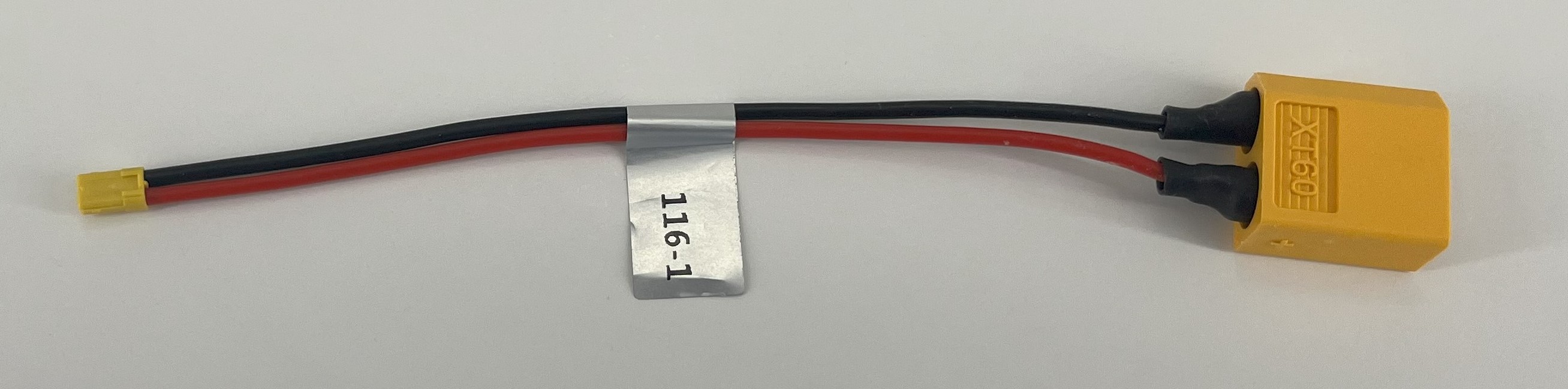
Description:
- ModalAI Yellow 2S-6S VBAT Format to XT60 Male Adapter/Extension Cable
Where Used:
- Embedded within ESC and VTX/VRX Assemblies
- Useful for general purpose JST eSFH connector hookups from a 2S-6S XT60 battery, with the yellow format
- Note: JST eSFH Red versions are ModalAI’s 5V format and Black/Grey are ModalAI’s 1S VBAT (3.8V) format
Details:
| Component | Details |
|---|---|
| Connector A | JST, SFHR-02V-L, 1.88 mm Housing, 2-POS |
| Connector B | AMASS, XT60U-M, Male plug, 2-POS |
| Length | 100mm |
| Insulator | Silicone |
| Color | Red(+), Black (-) |
| Gauge | 22 AWG |
| Weight | 4.9 grams |
Pinout:
| A | Signal | B | Signal |
|---|---|---|---|
| 1 | + (Red) | + | + |
| 2 | - (Black) | - | - |
Pinout, Part Number, & Additional Specs: See Drawing Here Contact ModalAI on the Forum for .DXF or .DWG formats of this drawing.
MCBL-00117
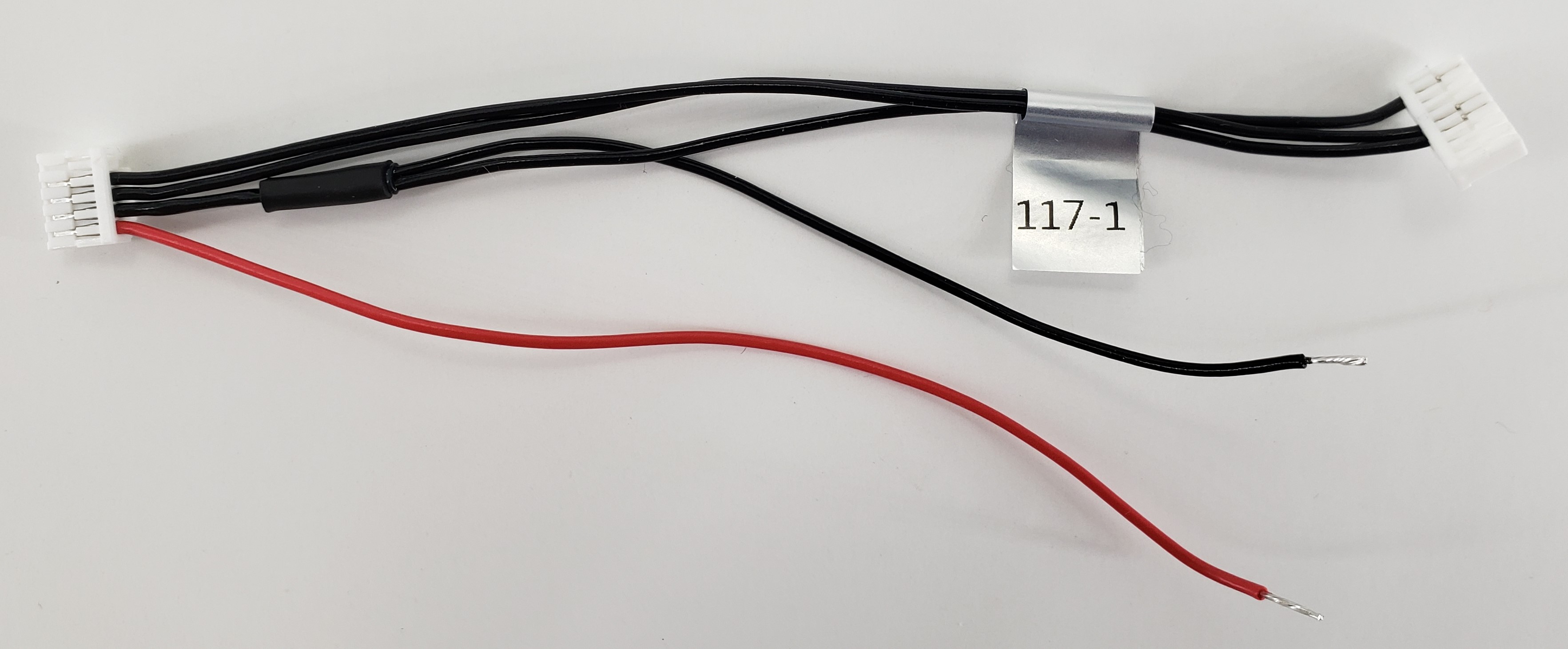
Description:
- Connects VOXL 2 Mini J10 SPI Port (in UART Mode) to HD Zero OSD/UART Port + Power Feed from VBAT using Pigtails
- This cable provides power to the HD Zero from a direct VBAT solder from an ESC or other capable source
- Note: HD Zero can pull over 13W in some power modes, be sure your VBAT power source can handle the correct HD Zero Voltage and 26AWG is suitable for the rated current
Where Used:
- VOXL 2 Mini to add OSD to the HD Zero VTX Unit with a DroneCode Compliant UART Port
- Stinger HD Zero Configurations
Details:
| Component | Details |
|---|---|
| Connector A | JST 1.25mm GHR-08V-S, VOXL 2 Mini UART, +3.3V signal levels |
| Connector B | JST 1.25mm GHR-05V-S, HD Zero Side, +3.3V signal levels |
| Pigtails | 100mm Red and Black, 5mm striped and tined. 26AWG |
| Length | 100mm (CONA-CONB), 100mm (pigtails) |
| Insulator | Flexible PVC |
| Color | Black, Red |
| Gauge | 26 AWG |
| Weight | 1.3 grams |
Pinout:
| A | V2 MINI Side | B | HD Zero | PG | VTX Power Source |
|---|---|---|---|---|---|
| 4 | UART TX | 2 | UART RX | ||
| 5 | UART RX | 3 | UART TX | ||
| 8 | FC GND | 4 | GND | 1 | GND |
| - | 5 | V+ (Load) | 2 | RED (Source) |
Pinout, Part Number, & Additional Specs: See Drawing Here Contact ModalAI on the Forum for .DXF or .DWG formats of this drawing.
MCBL-00118
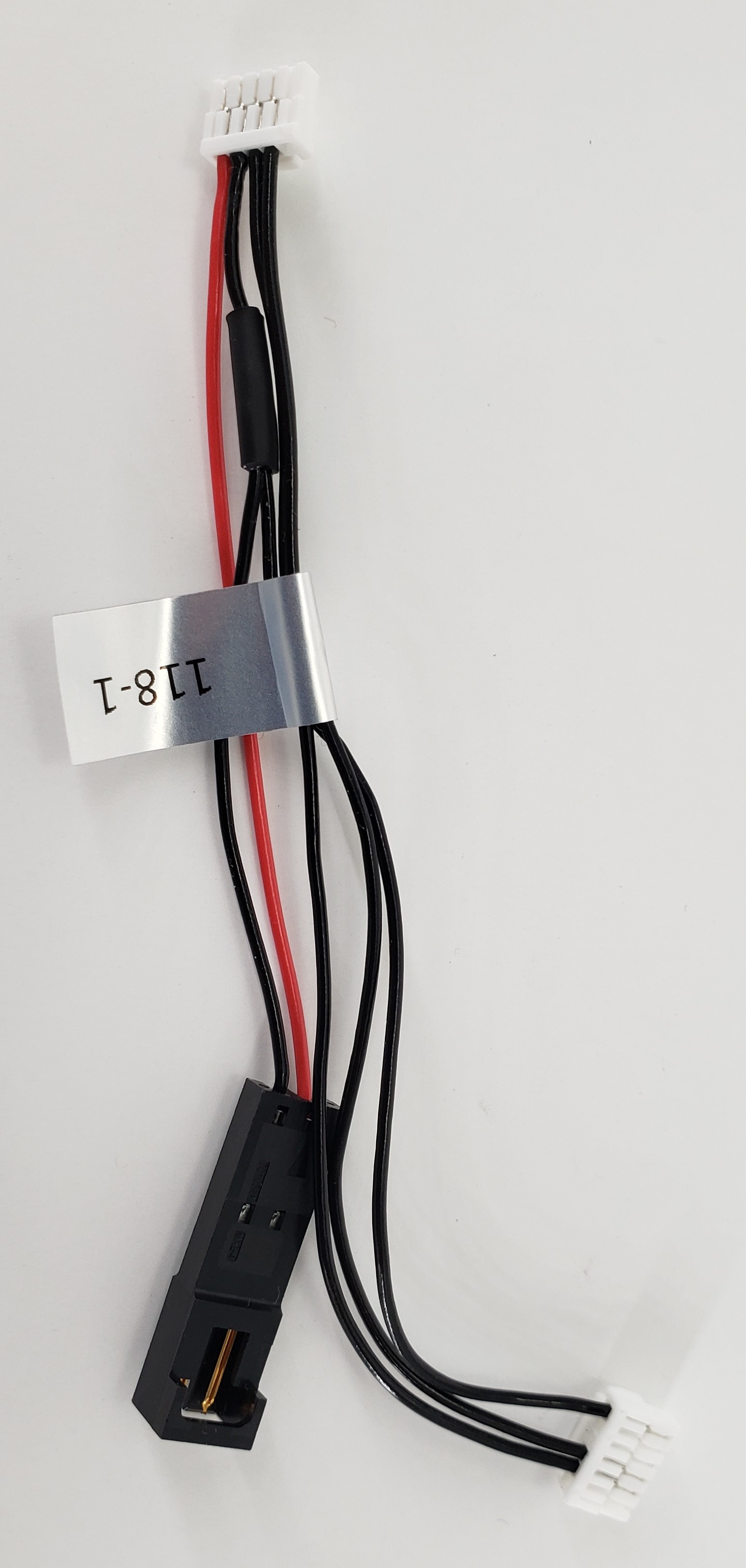
Description:
- Connects VOXL 2 or FCv2 Drone Code Compliant UART Port to HD Zero OSD/UART Port + Power Feed from VBAT using new VTX Format Connector
- This cable provides power to the HD Zero from a direct VBAT tap-off using MCBL-00123 on the ESC
- Note: HD Zero can pull over 13W in some power modes, be sure your VBAT power source can handle the correct HD Zero Voltage and 26AWG is suitable for the rated current
Where Used:
- Any Flight Controller that needs to add OSD to the HD Zero VTX Unit with a DroneCode Compliant UART Port
- Stinger HD Zero Configurations
Details:
| Component | Details |
|---|---|
| Connector A | JST 1.25mm GHR-06V-S, Flight Controller Side, +3.3V signal levels |
| Connector B | JST 1.25mm GHR-05V-S, HD Zero Side, +3.3V signal levels |
| Connector C | Molex SL-Series Housing 701070001, VBAT |
| Length | 100mm (CONA-CONB), 65mm (CONB-CONC) |
| Insulator | Flexible PVC |
| Color | Black, Red |
| Gauge | 26 AWG |
| Weight | 3.2 grams |
Pinout:
| A | FC Side | B | HD Zero | C | VTX Power Source |
|---|---|---|---|---|---|
| 2 | UART TX | 2 | UART RX | ||
| 3 | UART RX | 3 | UART TX | ||
| 6 | FC GND | 4 | GND | 2 | GND |
| - | 5 | V+ (Load) | 1 | RED (Source) |
Pinout, Part Number, & Additional Specs: See Drawing Here Contact ModalAI on the Forum for .DXF or .DWG formats of this drawing.
MCBL-00119
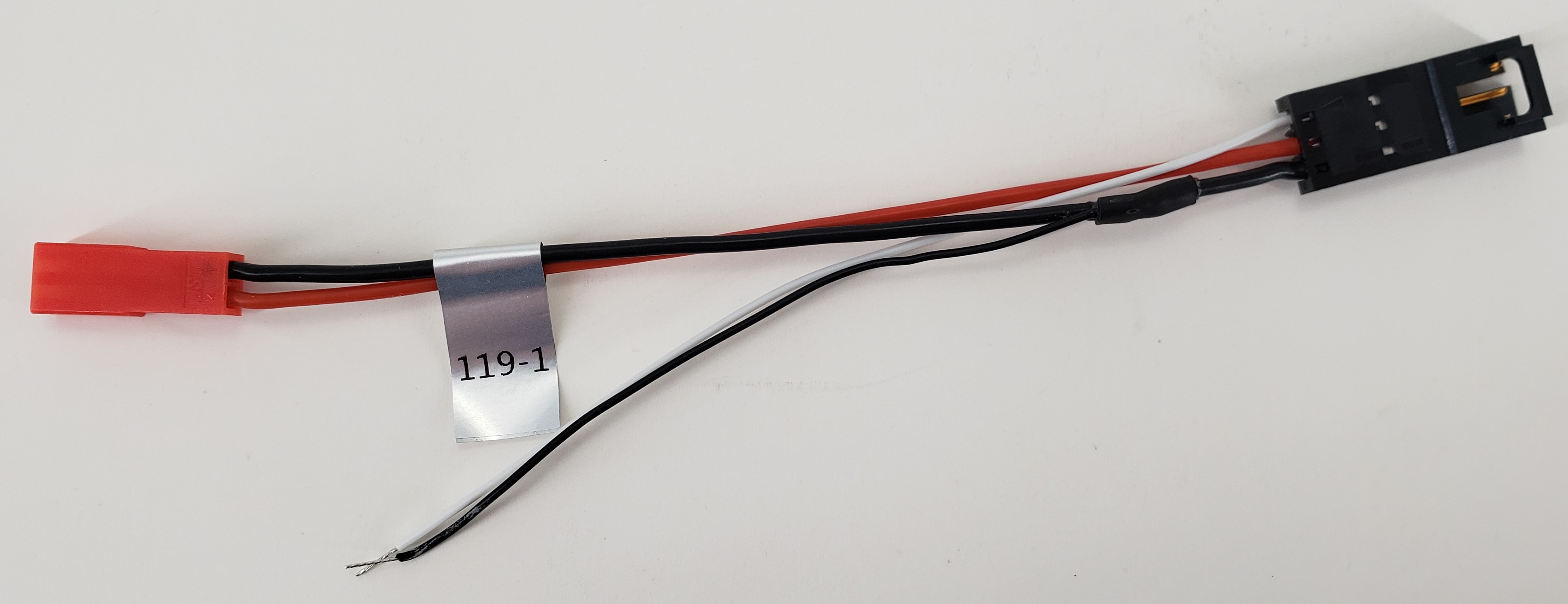
Description:
- Molex SL Based PWM Device Power and PWM Feeds
- LED Bar format, with JST SYR as power IN and Molex SL as device load
- PWM signals as pigtails to solder onto various RC receivers with extra PWM control outputs
Where Used:
- ModalAI Drones or for Standalone modules where a PWM type of device is needed with VBAT power from a JST SYR
- Follows common Hobby formats for pinouts
- Note the SYR is the ONLY ModalAI connector format with Pin 1 = GND, Pin 2 = VBAT to match hobbyist conventions
- Note the Molex 3-pin is the ONLY ModalAI connector format with Pin 1 = Signal, Pin 2 = VBAT, and Pin 3 = GND to match hobbyist conventions
Details:
| Component | Details |
|---|---|
| Connector A | JST Red SYR 2-Pos Receptacle Housing, SYR-02T |
| Connector B | Molex 3-Position SL Plug in PWM Format, 070107-0002 |
| Length | 100mm |
| Insulator | Silicone |
| Color | Black, Red, White |
| Gauge | 22 AWG (Power Red/Black), 28AWG (PWM signal white/black) |
| Weight | 3.1 grams |
Pinout:
| A | VBAT Source | B | PWM Device |
|---|---|---|---|
| 1 | GND | 3 | GND, with Pigtail Splice from PWM source |
| 2 | VBAT 2-6S (6.4-25.2V) | 2 | VBAT (Load) |
| 1 | Pigtail for PWM Input |
Pinout, Part Number, & Additional Specs: See Drawing Here Contact ModalAI on the Forum for .DXF or .DWG formats of this drawing.
MCBL-00120
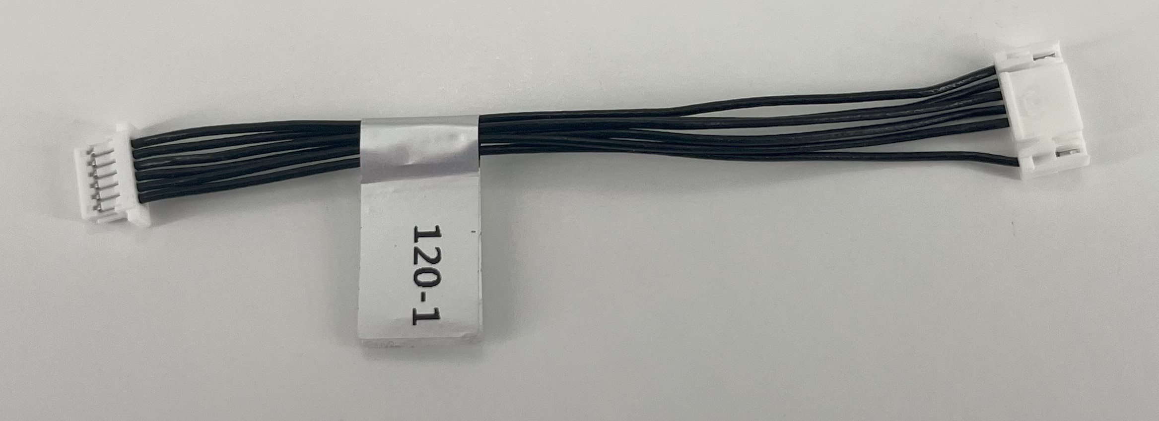
Description:
- 8-Pin VOXL 2 SPI JST GH to JST SH Jumper Cable
- Plugs into VOXL 2 J10 to bring the SPI port @ 3.3V to an external peripheral in 6-pin JST SH format without extra chip selects
Where Used:
- Sparrow for additional M0188-1 (not M0188-2) SPI Port
- General purpose conversion of 8-Pin JST GH to 6-Pin JST SH
Details:
| Component | Details |
|---|---|
| Connector A | JST, GHR-08V-S, 1.25 mm Housing, 8-POS |
| Connector B | JST, SHR-06V-S-B, 1.0 mm Housing (with Protrusions), 6-POS |
| Length | 75mm |
| Insulator | PVC (flexible) |
| Color | Black |
| Gauge | 28 AWG |
| Weight | 1.0 grams |
Pinout:
| SIGNAL | CON A | CON B | |
|---|---|---|---|
| 3P3V_VREG_LOCAL | Pin1 | 1 | Pin1 |
| SPI_MOSI_3P3V | Pin2 | 2 | Pin2 |
| SPI_MOSI_3P3V | Pin3 | 3 | Pin3 |
| SPI_SCLK_3P3V | Pin4 | 4 | Pin4 |
| SPI_CS0_3P3V | Pin5 | 5 | Pin5 |
| DGND | Pin8 | 6 | Pin6 |
Pinout, Part Number, & Additional Specs: See Drawing Here Contact ModalAI on the Forum for .DXF or .DWG formats of this drawing.
MCBL-00121
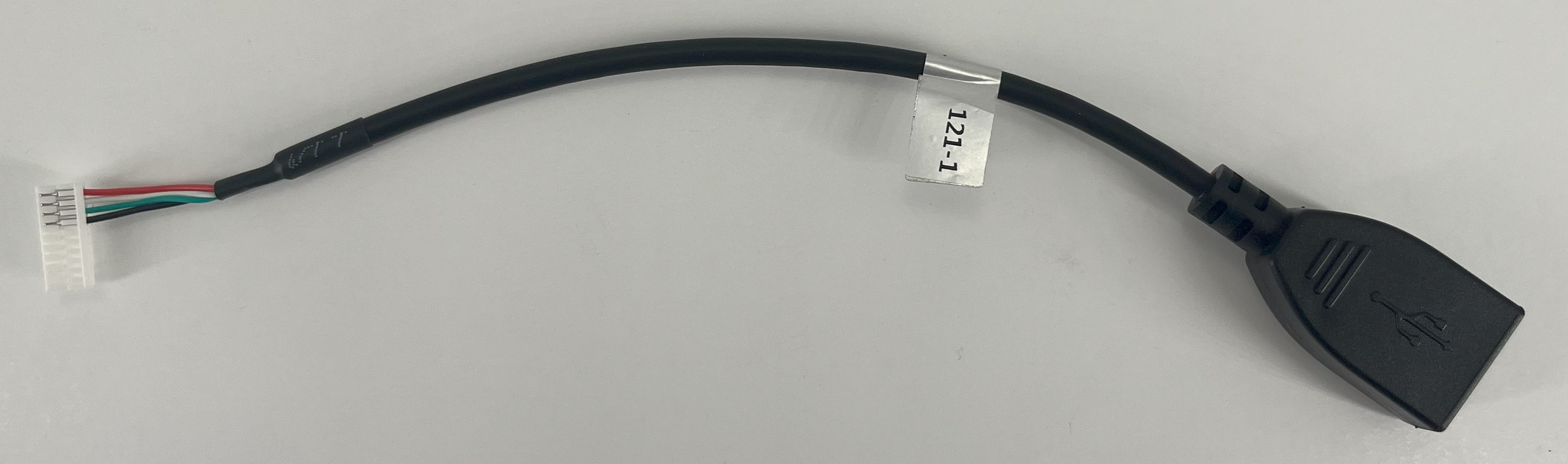
Description:
- 10-pin JST to USBA Female/Receptacle Cable
- 10-pin version of MCBL-00041
- Note there are two versions of this cable
- (-1) is nominally as shown here
- (-2) is the same exact functional cable, but the outer insulation around the cable conductors has been trimmed back to 1/2 the overall cable length to allow for tighter installations.
Where Used:
- Used for connecting ModalAI USB Hosts with the 10-Pin JST format (examples below) to USB Peripherals (Type A side)
- VOXL 2 USB3.0 / UART Expansion Adapter to USB peripheral device
- VOXL 2 Cellular LTE, I/O Breakout and USB hub add-on (M0130-3)
- 5G Modem Carrier Board, USB HUB, I/O Breakout for VOXL 2
Details:
| Component | Details |
|---|---|
| Connector A | JST, GHR-10V-S |
| Connector B | USB 2.0 Type A Female/Receptacle |
| Length | ~150 mm |
| Insulator | PVC |
| Color | Black, Red, White/Green TP |
| Gauge | 26AWG VBUS/GND, 28AWG Twisted Pair Signals |
| Weight | 12.9 grams (-1), 12.3 grams (-2) |
Pinout:
| A | VOXL 2 HOST SIDE | B | USB Peripheral Side |
|---|---|---|---|
| 1 | VBUS (Source) | 1 | VBUS (Load) |
| 2 | DATA_M | 2 | D- |
| 3 | DATA_P | 3 | D+ |
| 4 | GND | 4 | GND |
Pinout, Part Number, & Additional Specs: See -1 Drawing Here, See -2 Drawing Here Contact ModalAI on the Forum for .DXF or .DWG formats of this drawing.
MCBL-00122
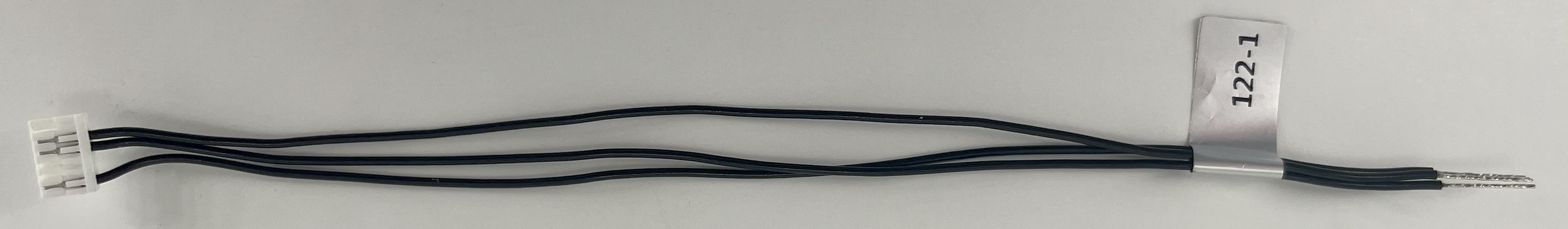
Description:
- Cable providing a partial (sub-populated) JST GH 6-pin breakout, with just pins 2 & 3 & 6.
Where Used:
- Great for FCv2 or VOXL 2 Add-in board connections with a 6-pin JST GH connector for UART only tap-offs, with a Ground wire (pin 6)
- Note: pigtail side is tinned for ~10mm making it easy to install JST SSHL-002T-P0.2 pins if needed
- Great item to have for making your own cables!!
Details:
| Component | Details |
|---|---|
| Connector A | JST 1.25mm GHR-06V-S |
| Connector B | None: Pigtails |
| Length | 150mm (10mm pigtails) |
| Insulator | PVC (flexible) |
| Color | Black |
| Gauge | 26 AWG |
| Weight | 1.2 grams |
Pinout:
| A | |||
|---|---|---|---|
| 1 | - | ||
| 2 | 2 | (pigtail) | |
| 3 | 3 | (pigtail) | |
| 4 | - | ||
| 5 | - | ||
| 6 | 6 | (pigtail) |
Pinout, Part Number, & Additional Specs: See Drawing Here Contact ModalAI on the Forum for .DXF or .DWG formats of this drawing.
MCBL-00123
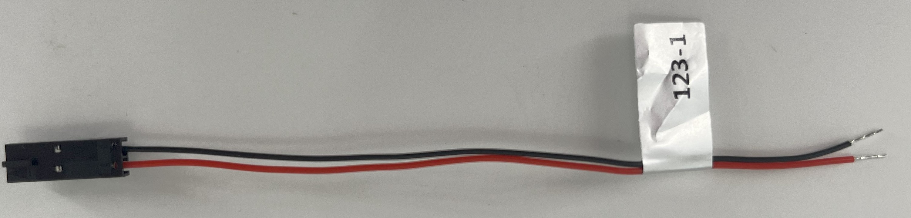
Description:
- 2-pin Molex SL-Series Keyed Receptacle to Pigtails
- Red (Pin 1) and Black (Pin 2) cables for easy pin 1 identification
- Multiple pigtail lengths to start from (60mm, 100mm, & 150mm)
Where Used:
- ModalAI Drones with the need to a deliver low current signals (like RPM/PWM) or VBATT/GND
- General purpose use where the need for a simple 2-Pin with keying and retention latches are needed
- See the Mating product MCBL-00124 for a complete solution
Details:
| Component | Details |
|---|---|
| Connector A | Molex, SL-Series Receptacle, 50579402 |
| Connector B | Pigtails, stripped and tinned 5mm |
| Length | 100mm (-1 variant), 150mm (-2 variant), 60mm (-3 variant) |
| Insulator | Siicone |
| Color | Black, Red |
| Gauge | 28AWG |
| Weight | 0.6g (-1 variant), 0.8g (-2 variant), 0.5g (-3 variant) |
Pinout:
| A | B | ||
|---|---|---|---|
| 1 | Pin 1 (Red) | 1 | (Pigtail) |
| 2 | Pin 2 (Black) | 2 | (Pigtail) |
Pinout, Part Number, & Additional Specs: See -1 Drawing Here, See -2 Drawing Here,See -3 Drawing Here. Contact ModalAI on the Forum for .DXF or .DWG formats of this drawing.
MCBL-00124
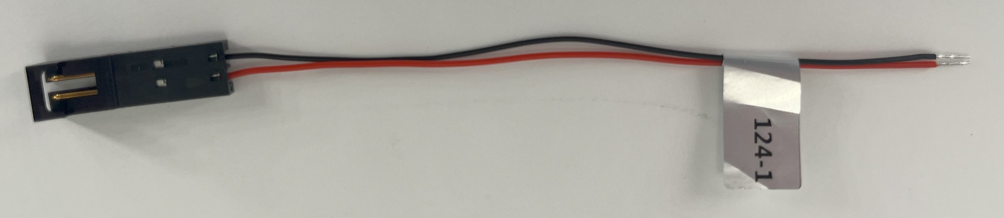
Description:
- 2-pin Molex SL-Series Keyed Plug to Pigtails
- Red (Pin 1) and Black (Pin 2) cables for easy pin 1 identification
- Multiple pigtail lengths to start from (100mm & 150mm)
Where Used:
- ModalAI Drones with the need to a deliver low current signals (like RPM/PWM) or VBATT/GND
- General purpose use where the need for a simple 2-Pin with keying and retention latches are needed
- See the Mating product MCBL-00123 for a complete solution
Details:
| Component | Details |
|---|---|
| Connector A | Molex, SL-Series Plug, 50579402 |
| Connector B | Pigtails, stripped and tinned 5mm |
| Length | 100mm (-1 variant), 150mm (-2 variant) |
| Insulator | Silcione |
| Color | Black, Red |
| Gauge | 28AWG |
| Weight | 0.6g (-1 variant), 0.8g (-2 variant) |
Pinout:
| A | B | ||
|---|---|---|---|
| 1 | Pin 1 (Red) | 1 | (Pigtail) |
| 2 | Pin 2 (Black) | 2 | (Pigtail) |
Pinout, Part Number, & Additional Specs: See -1 Drawing Here, See -2 Drawing Here. Contact ModalAI on the Forum for .DXF or .DWG formats of this drawing.
MCBL-00125
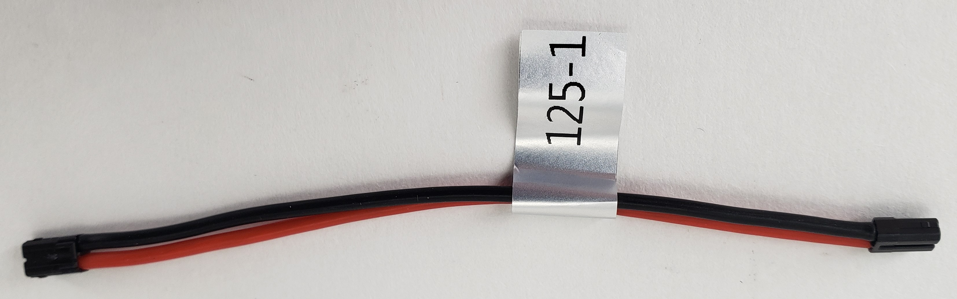
Description:
- ModalAI Black 3.8V 1S VBAT Format End-to-End Extension Cable
- This new black JST SFHR format is being used as a substitute to the larger Molex MicroOne solution on some VOXL 2 Mini based designs in process
- Note we have several variants for length as described in the table below
Where Used:
- Useful for general purpose JST eSFH connector hookups, with the black format
- Note: Red version are ModalAI’s 5V format and Yellow are ModalAI’s 2S-6S VBAT format
Details:
| Component | Details |
|---|---|
| Connector A & B | JST, SFHR-02V-T-K, 1.8mm Housing, 2-POS |
| Length | 75mm (-1 variant), 125mm (-2 variant), 45mm (-3 variant) |
| Insulator | Silicone |
| Color | Red/Black |
| Gauge | 22 AWG |
| Weight | 1 gram (-1 variant), 1.5 grams (-2 variant), 0.7 grams (-3 variant) |
Pinout:
| A | Signal | B | Signal |
|---|---|---|---|
| 1 | + (Red) | 1 | + |
| 2 | - (Black) | 2 | - |
Pinout, Part Number, & Additional Specs: See -1 Drawing Here, See -2 Drawing Here, See -3 Drawing Here Contact ModalAI on the Forum for .DXF or .DWG formats of this drawing.
MCBL-00126
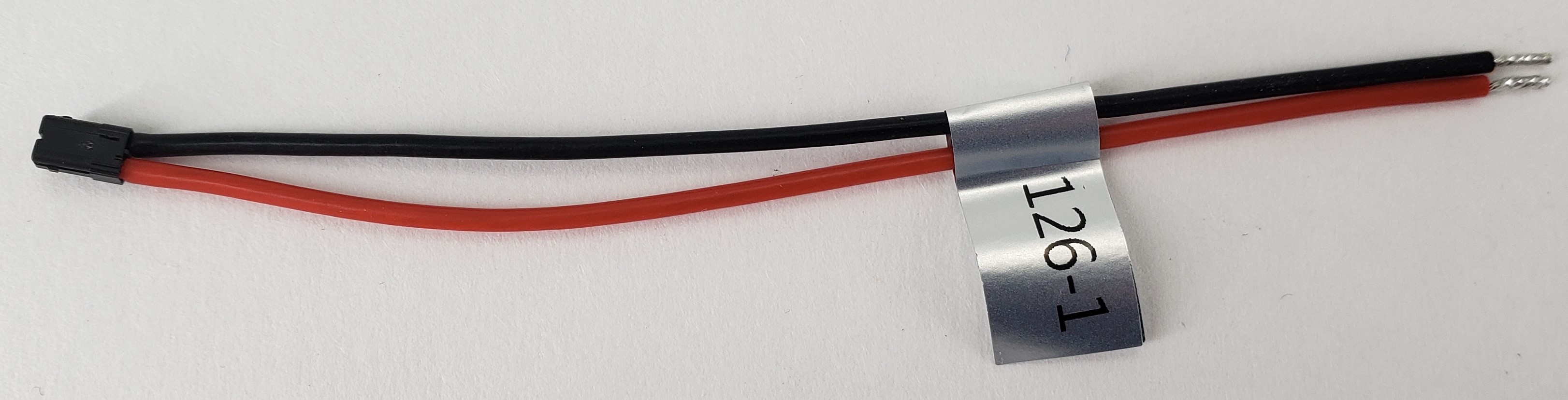
Description:
- ModalAI Black 3.8V 1S VBAT Format End-to-End Breakout to Pigtail Cable
- This new black JST SFHR format is being used as a substitute to the larger Molex MicroOne solution on VOXL 2 Mini
- Useful for soldering onto 3.8V power module pads to provide VOXL 2 Mini 1S VBAT
Where Used:
- Useful for general purpose JST eSFH connector hookups, with the black format
- Note: Red version are ModalAI’s 5V format and Yellow are ModalAI’s 2S-6S VBAT format
Details:
| Component | Details |
|---|---|
| Connector A | JST, SFHR-02V-T-K, 1.8mm Housing, 2-POS |
| Length | 100mm |
| Insulator | Silicone |
| Color | Red/Black |
| Gauge | 22 AWG |
| Weight | 1.1 grams |
Pinout:
| A | Signal | B | Pigtail |
|---|---|---|---|
| 1 | + (Red) | 1 | + |
| 2 | - (Black) | 2 | - |
Pinout, Part Number, & Additional Specs: See Drawing Here, Contact ModalAI on the Forum for .DXF or .DWG formats of this drawing.
MCBL-00127
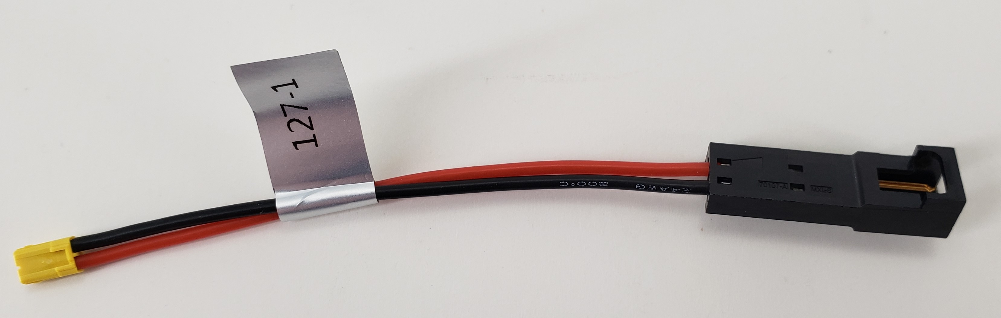
Description:
- New ModalAI Yellow VBAT Format to New VTX Power Format
- Converts Yellow VBAT (2-6S) JST Payload Connectors to VTX Molex SL Plug Format
Where Used:
- VTX Assemblies integrated into ModalAI Drones or for Standalone modules
Details:
| Component | Details |
|---|---|
| Connector A | Molex SL Series Housing 701070001 with Pin contact 16020077 |
| Connector B | JST 1.8mm SFHR-02V-L |
| Length | 65mm |
| Insulator | Silicone |
| Color | Black, Red |
| Gauge | 24 AWG |
| Weight | 1.4 grams |
Pinout:
| A | VBAT Payload/VTX | B | ESC/Battery/Source |
|---|---|---|---|
| 1 | VBAT (Load) | 1 | VBAT (Source) 2-6S (6.4-25.2V) |
| 2 | GND | 2 | GND |
Pinout, Part Number, & Additional Specs: See Drawing Here Contact ModalAI on the Forum for .DXF or .DWG formats of this drawing.
MCBL-00128
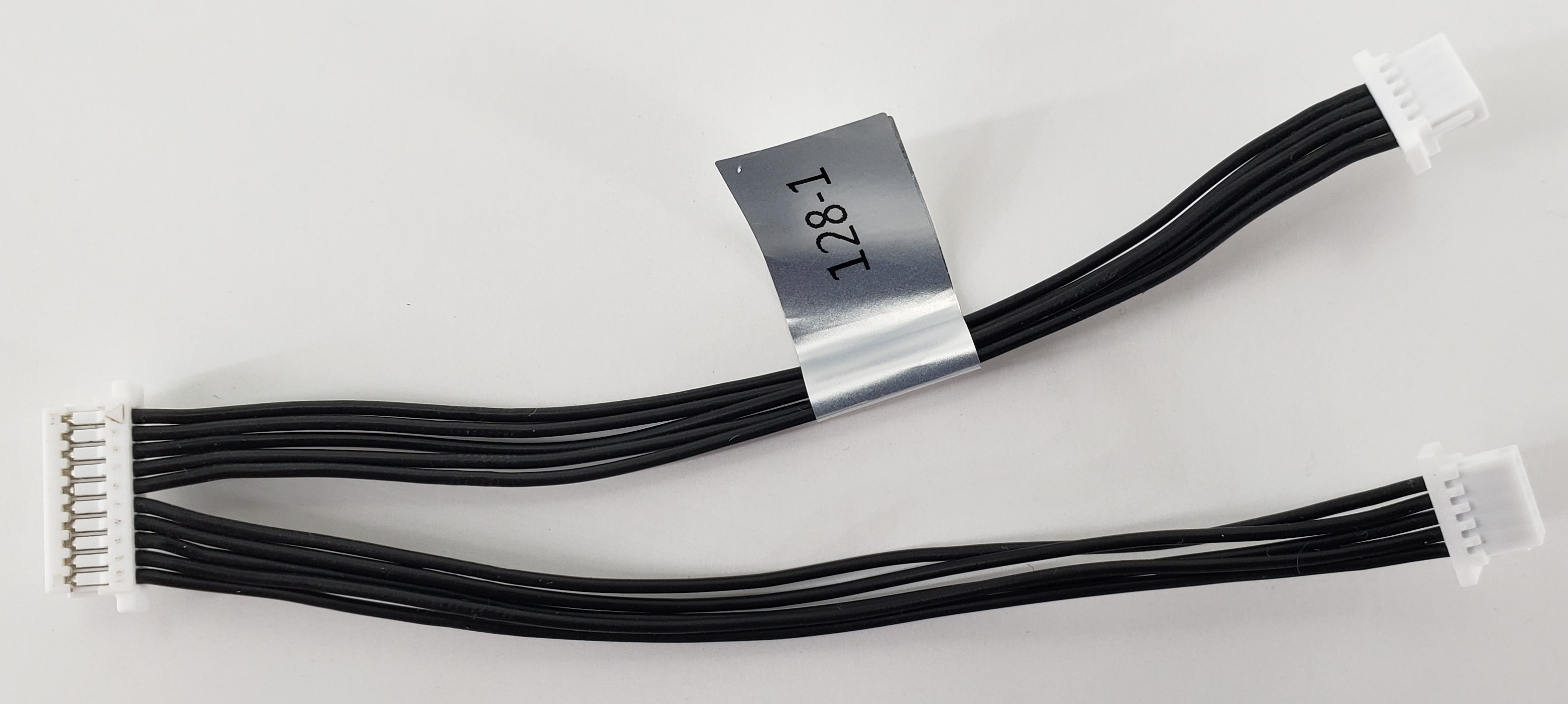
Description:
- Connects M0188/M0195 Sparrow/Stinger Imager Front End to Two ToF “Pill” Modules, M0189
Where Used:
- Sparrow/Stinger Drones with Single Point ToF modules
Details:
| Component | Details |
|---|---|
| Connector A | JST 1.0mm SHR-10V-S-B, Imager Front End Side |
| Connector B | JST 1.0mm SHR-05V-S-B, ToF Pill (M0189) Side |
| Connector C | JST 1.0mm SHR-05V-S-B, ToF Pill (M0189) Side |
| Length | 75mm |
| Insulator | Silicone |
| Color | Black |
| Gauge | 28 AWG |
| Weight | 1.4 grams |
Pinout:
| Signal | CON A | CON B | CON C |
|---|---|---|---|
| 1 | 1 | 1 | |
| 2 | 2 | 2 | |
| 3 | 3 | 3 | |
| 4 | 4 | 4 | |
| 5 | 5 | 5 | |
| 6 | 6 | 1 | |
| 7 | 7 | 2 | |
| 8 | 8 | 3 | |
| 9 | 9 | 4 | |
| 10 | 10 | 5 |
Pinout, Part Number, & Additional Specs: See Drawing Here Contact ModalAI on the Forum for .DXF or .DWG formats of this drawing.
MCBL-00129
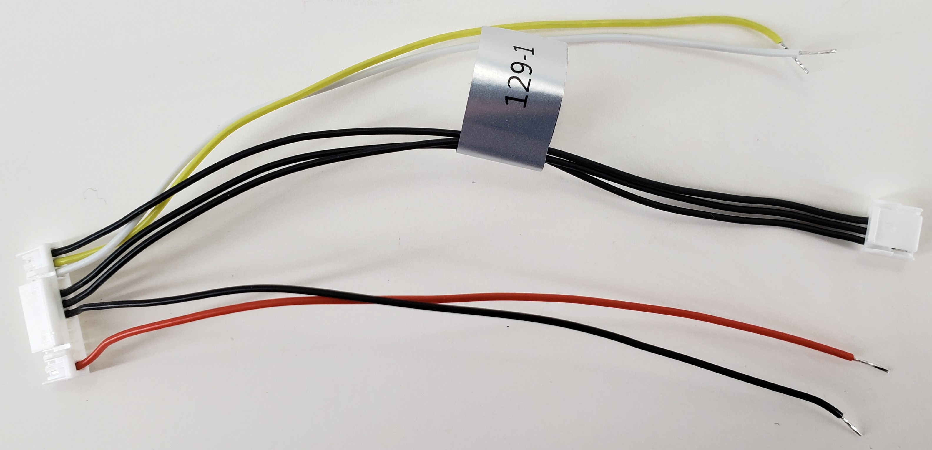
Description:
- Connects VOXL 2 Mini J19 to ModalAI Mini ESC (M0129) UART + an R/C unit 2W (TX/RX) UART via pigtails
- This cable provides power to the R/C module at 5V (Mini ESC is powered from a battery)
- All pigtails are stripped and tinned for 5mm
Where Used:
- ModalAI Stinger Drone, with VOXL 2 Mini
- Any fully-featured VOXL 2 Mini drone that requires J19 for ESC and R/C UARTs
Details:
| Component | Details |
|---|---|
| Connector A | JST 1.25mm GHR-12V-S, VOXL 2 Mini side, +3.3V signal levels |
| Connector B | JST 1.25mm GHR-04V-S, ESC side, +3.3V signal levels |
| Length | 100mm (CONA-CONB), 100mm (pigtails) |
| Insulator | Silicone |
| Color | Black, Red, White, Yellow |
| Gauge | 28 AWG |
| Weight | 1.3 grams |
Pinout:
| A | VOXL 2 Mini | B | M0129 ESC | Pigtails |
|---|---|---|---|---|
| 1 | 5V (Source) | Red | ||
| 2 | - | |||
| 3 | - | |||
| 4 | - | |||
| 5 | - | |||
| 6 | GND | Black | ||
| 7 | ESC_UART_TX | 2 | UART_RX | |
| 8 | ESC_UART_RX | 3 | UART_TX | |
| 9 | - | |||
| 10 | RC_UART_TX | White | ||
| 11 | RC_UART_RX | Yellow | ||
| 12 | GND | 4 |
Pinout, Part Number, & Additional Specs: See Drawing Here Contact ModalAI on the Forum for .DXF or .DWG formats of this drawing.
MCBL-00130
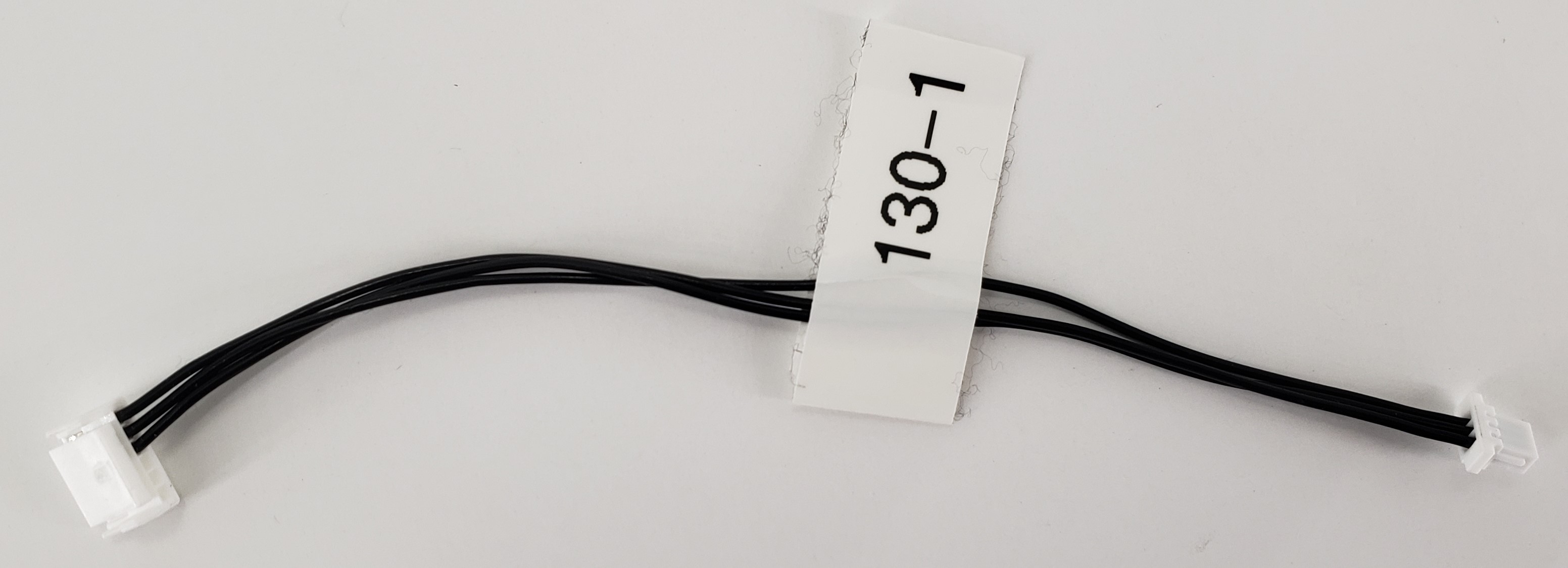
Description:
- ModalAI 6-pin JST GGH DroneCode Compliant UART+I2C port to 3-pin JST SH for I2C
- New 3-pin I2C format for accesory sensors (ADC, Temp, etc)
- I2C + GND only, no power pickup
Where Used:
- VTX assemblies with M0154 + M0130/M0090 where a sensor board exists
- Useful for general purpose lab use to access I2C from our JST GH Dronecode formats
Details:
| Component | Details |
|---|---|
| Connector A | JST, GHR-06V-S, VOXL 2 Side |
| Connector B | JST, SHR-03V-S-B, Sensor Board Side |
| Length | 100mm |
| Insulator | Flexible PVC |
| Color | Black |
| Gauge | 28 AWG |
| Weight | 0.6 grams |
*Please note our first batch of cables did not include a label and only a temporary one is shown in the image here. Product received may or may not include a label.
Pinout:
| A | Signal (Host Side) | B | Signal (Target Side) |
|---|---|---|---|
| 1 | |||
| 2 | |||
| 3 | |||
| 4 | SDA | 2 | SDA |
| 5 | SCL | 1 | SCL |
| 6 | GND | 3 | GND |
Pinout, Part Number, & Additional Specs: See Drawing Here Contact ModalAI on the Forum for .DXF or .DWG formats of this drawing.
MCBL-00131
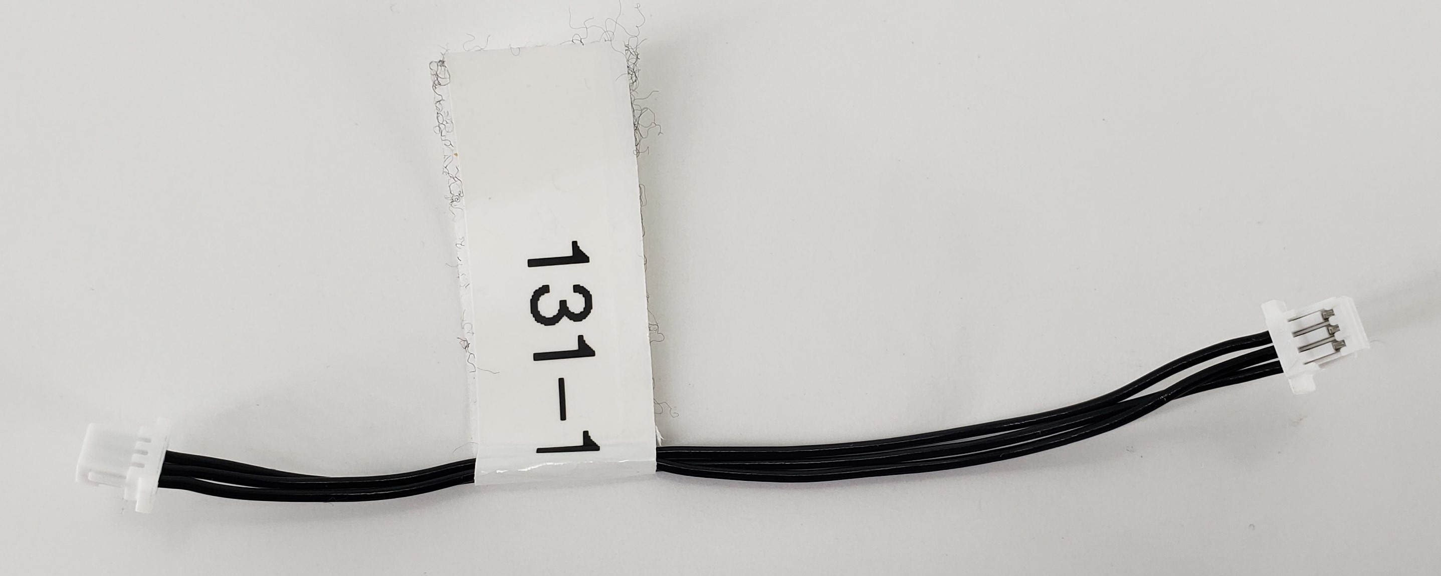
Description:
- New 3-pin I2C format for accesory sensors (ADC, Temp, etc) direct to 3-pin I2C
- I2C + GND only (as intended, but can be used as 3 general purpose conductors)
- Two variants exist:
- (-1) is nominally 75mm in length and (-2) at 40mm in length
Where Used:
- VTX assemblies with M0104/M0204 + M0194 where a sensor board exists
- Useful for general purpose lab use for 3-pin JST SH
Details:
| Component | Details |
|---|---|
| Connector A | JST, SHR-03V-S-B, VOXL 2 Mini Adapter Side |
| Connector B | JST, SHR-03V-S-B, Sensor Board Side |
| Length | 75mm (-1), 40mm (-2) |
| Insulator | Flexible PVC |
| Color | Black |
| Gauge | 28 AWG |
| Weight | 0.5 grams (-1), 0.3 grams (-2) |
*Please note our first batch of cables did not include a label and only a temporary one is shown in the image here. Product received may or may not include a label.
Pinout:
| A | Signal | B | Signal |
|---|---|---|---|
| 1 | 1 | 1 | 1 |
| 2 | 2 | 2 | 2 |
| 3 | 3 | 3 | 3 |
Pinout, Part Number, & Additional Specs: See -1 Drawing Here, See -2 Drawing Here Contact ModalAI on the Forum for .DXF or .DWG formats of this drawing.
MCBL-00132
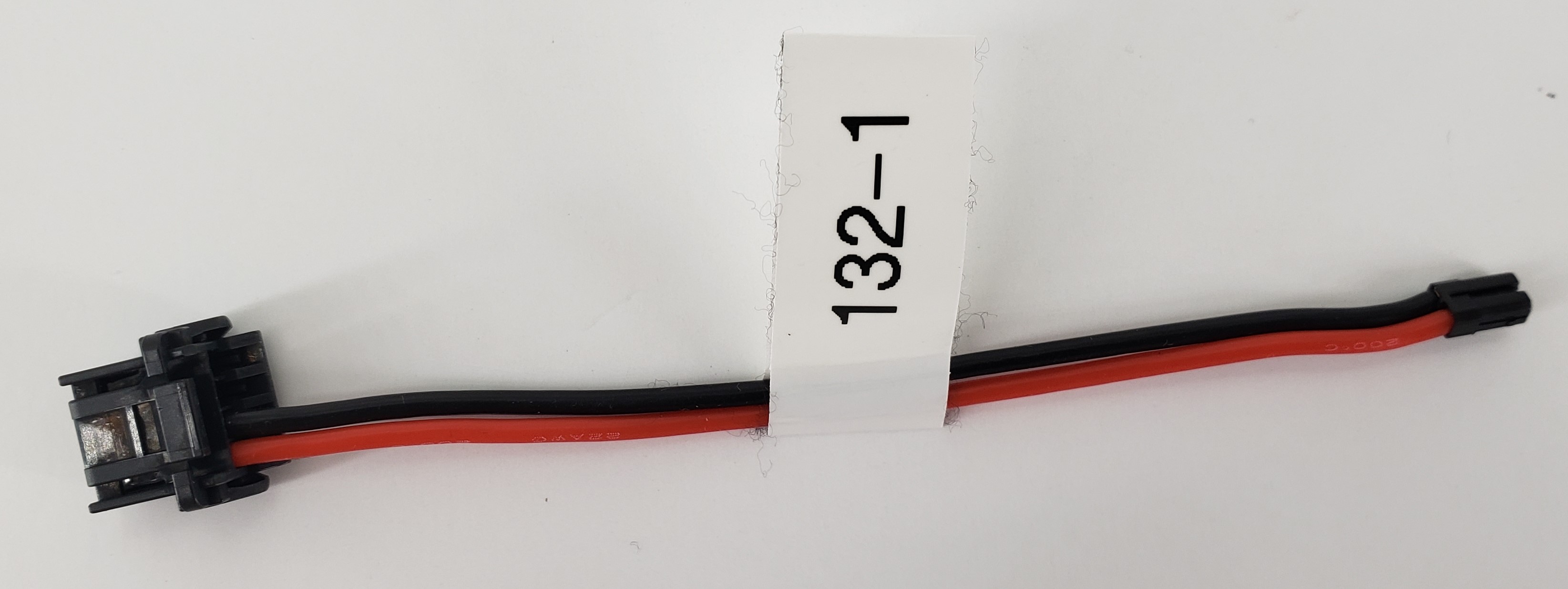
*Please note our first batch of (-1) variant cables did not include a label and only a temporary one is shown in the image here. Product received may or may not include a label.
Description:
- ModalAI 4-pin MicroOne connector used on VOXL 2 Mini to Black JST (1S 3.8V format)
- Power Leads Only (1&2), no I2C bus cables (3&4)
- Note there are 2 variants, (-1) nominally at 80mm, and (-2) shorter length for 20mm
Where Used:
- Embedded within VTX assemblies with M0204
- Useful for general purpose JST eSFH connector hookups, with the black format, for VOXL 2 Mini
- Note: Red version are ModalAI’s 5V format and Black/Grey are ModalAI’s 1S VBAT (3.8V) format
Details:
| Component | Details |
|---|---|
| Connector A | Molex 2.0mm MicroOne 2059792041 |
| Connector B | JST, SFHR-02V-T-K, 1.8mm Housing, 2-POS |
| Length | 80mm (-1), 20mm (-2) |
| Insulator | Silicone |
| Color | Red/Black |
| Gauge | 22 AWG |
| Weight | 1.5 grams (-1), 0.9 grams (-2) |
Pinout:
| A | Signal | B | Signal |
|---|---|---|---|
| 1 | + (Red) | 1 | + |
| 2 | - (Black) | 2 | - |
| 3 | |||
| 4 |
Pinout, Part Number, & Additional Specs: See -1 Drawing Here, See -2 Drawing Here, Contact ModalAI on the Forum for .DXF or .DWG formats of this drawing.
MCBL-00133
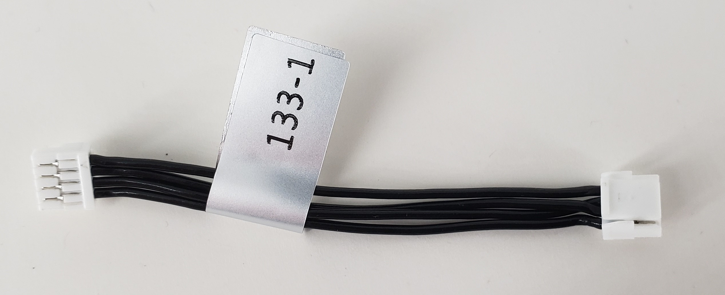
Description:
- 4pin-JST-to-4pin-JST cable (cross-over 1:1, 2:3, 3:2, 4:4)
- Exactly like MCBL-00015-3 but with pins 2&3 swapped for Cross-over UART
Where Used:
- Great item to have for making your own cables!!
- JST 4-pin Applications with TX/RX to TX/RX on same pin 2&3 at each board
Details:
| Component | Details |
|---|---|
| Connector A | JST, GHR-04V-S |
| Connector B | JST, GHR-04V-S |
| Length | 50mm |
| Insulator | PVC (flexible) |
| Color | Black |
| Gauge | 26 AWG |
| Weight | 1.1 grams |
Pinout:
| A | B | ||
|---|---|---|---|
| 1 | Pin1 | 1 | Pin1 |
| 2 | Pin2 | 2 | Pin3 |
| 3 | Pin3 | 3 | Pin2 |
| 4 | Pin4 | 4 | Pin4 |
Pinout, Part Number, & Additional Specs: See Drawing Here Contact ModalAI on the Forum for .DXF or .DWG formats of these drawings.
MCBL-00137
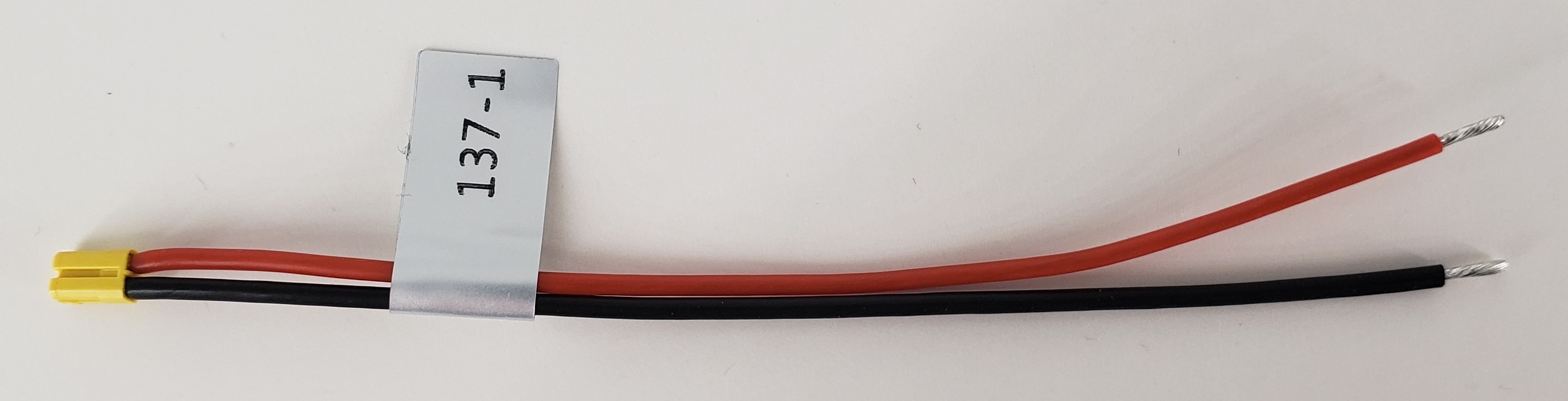
Description:
- ModalAI Yellow VBAT Format (2S-6S) Pigtail Cable, 100mm
- This new yellow JST SFHR format is being used in places of larger XT-30 or XT-60 connectors as a micro board connector option
Where Used:
- Useful for general purpose JST eSFH connector hookups, with the yellow format
- Useful for soldering onto power module or ESC pads to provide 2S-6S VBAT power to ModalAI products
- Note: Red version are ModalAI’s 5V format and Yellow are ModalAI’s 2S-6S VBAT format
Details:
| Component | Details |
|---|---|
| Connector A | JST, SFHR-02V-L, 1.8mm Housing, 2-POS Yellow |
| Length | 100mm |
| Insulator | Silicone |
| Color | Red/Black |
| Gauge | 22 AWG |
| Weight | 1.1 grams |
Pinout:
| A | Signal | B | Pigtail |
|---|---|---|---|
| 1 | + (Red) | 1 | + |
| 2 | - (Black) | 2 | - |
Pinout, Part Number, & Additional Specs: See Drawing Here, Contact ModalAI on the Forum for .DXF or .DWG formats of this drawing.
MCBL-00138
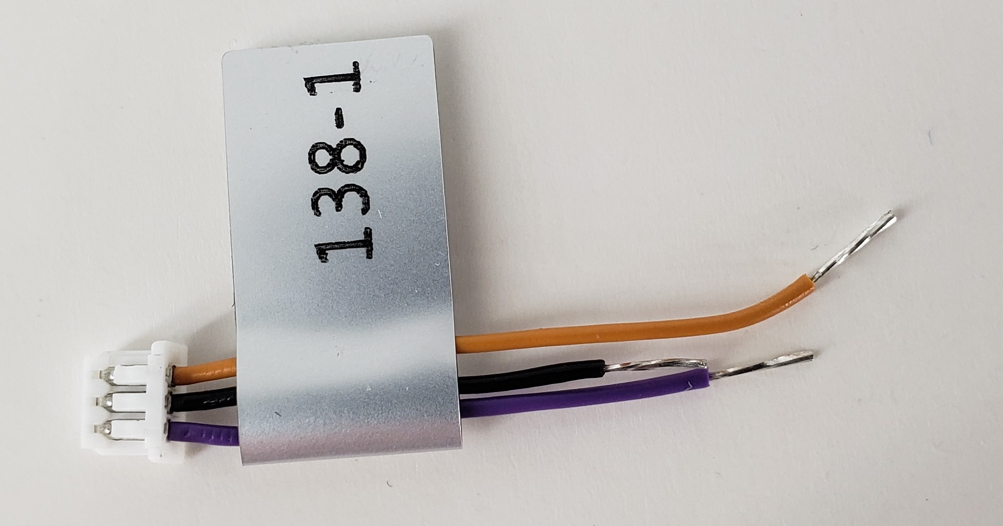
Description:
- ModalAI PWM Type 2-B (3-pin Molex Picoblade) Cable
- Receptacle Housing side meant for RC Receivers with 2 PWM signal outs + shared GND ref
Where Used:
- Stinger Drone
- Multi-length variant tuned specifically for TBS
Details:
| Component | Details |
|---|---|
| Connector A | Molex, 0510210300, 3-POS PicoBlade Receptacle Housing |
| Length | 25mm/30mm/35mm (black/purple/orange) |
| Insulator | Flexible PVC |
| Color | Black/Purple/Orange |
| Gauge | 28 AWG |
| Weight | 0.2 grams |
Pinout:
| A | Signal | B | Pigtails |
|---|---|---|---|
| 1 | PWM1 (Purple) | - | |
| 2 | GND (Black) | - | |
| 3 | PWM2 (Orange) | - |
Pinout, Part Number, & Additional Specs: See Drawing Here Contact ModalAI on the Forum for .DXF or .DWG formats of this drawing.
MCBL-00146
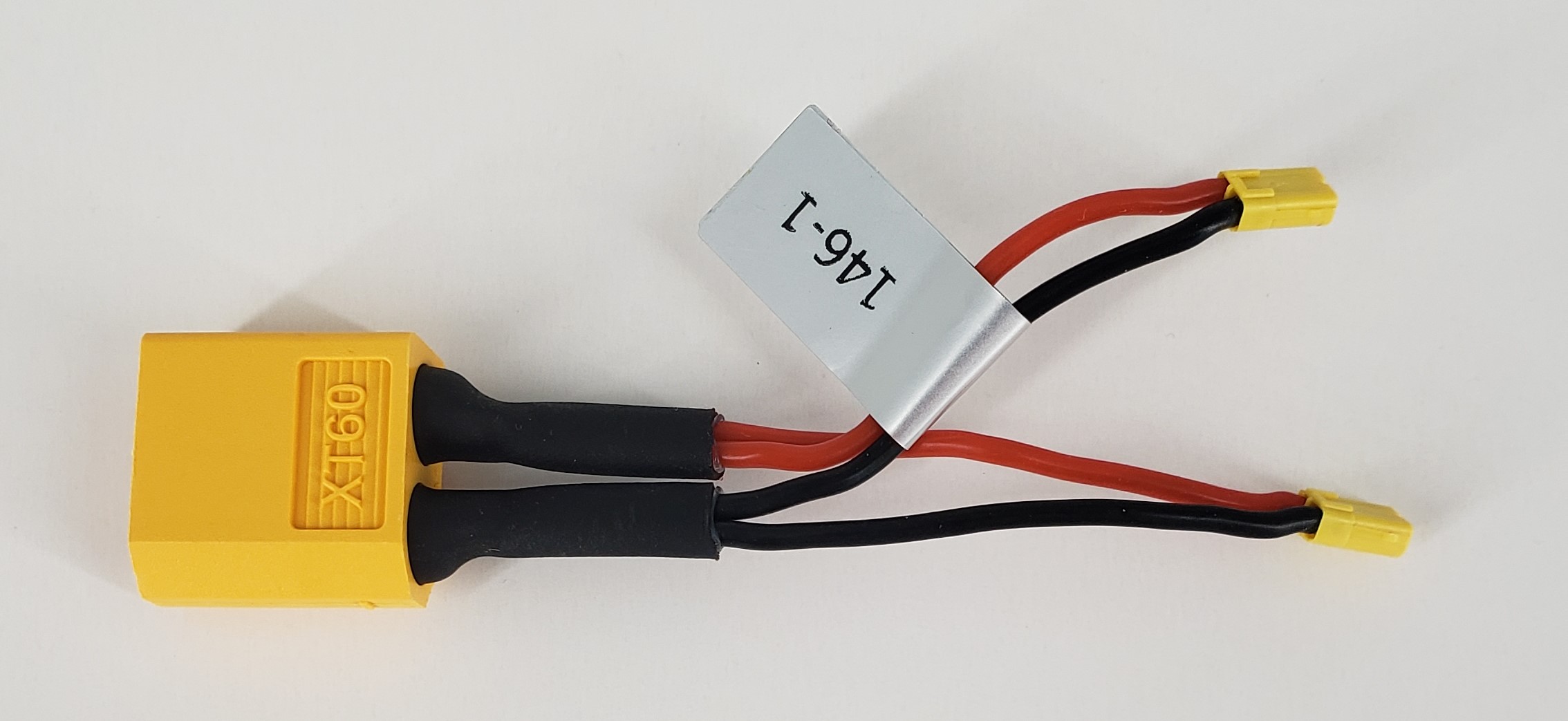
Description:
- Dual ModalAI Yellow 2S-6S VBAT Format to XT60 Male Cable
- Just like MCBL-00116-1, but a Y-splitter
Where Used:
- Embedded within ESC and VTX/VRX Assemblies
- Useful for general purpose JST eSFH connector hookups from a 2S-6S XT60 battery, when there are two boards with the yellow format
- Note: JST eSFH Red versions are ModalAI’s 5V format and Black/Grey are ModalAI’s 1S VBAT (3.8V) format
Details:
| Component | Details |
|---|---|
| Connector A | AMASS, XT60U-M, Male plug, 2-POS |
| Connector B/C | JST, SFHR-02V-L, 1.88 mm Housing, 2-POS |
| Length | 50mm (each split) |
| Insulator | Silicone |
| Color | Red(+), Black (-) |
| Gauge | 22 AWG |
| Weight | 5.1 grams |
Pinout:
| A | Signal (Source) | B | Signal | C | Signal |
|---|---|---|---|---|---|
| + | + (Red) | 1 | + | 1 | + |
| - | - (Black) | 2 | - | 2 | - |
Pinout, Part Number, & Additional Specs: See Drawing Here Contact ModalAI on the Forum for .DXF or .DWG formats of this drawing.
MCBL-00151
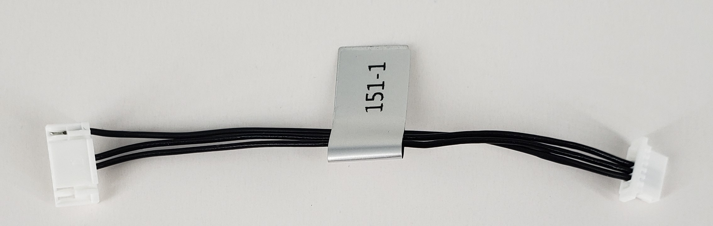
Description:
- 8-Pin VOXL 2 UART JST GH to JST SH Jumper Cable for Rotor Riot Brave F7
- Plugs into VOXL 2 J10 to connect directly to the Brave F7 Flight Conteoller OSD UART Port @ 3.3V
- RX, TX, and GND Only
- Note there are two variants
- (-1) at 75mm, and (-2) at 100mm for slightly larger frames
Where Used:
- Customers that wish to use V2 Mini for VTX, yet BraveF7 for FC
- ModalAI Shikra DIY Drone
Details:
| Component | Details |
|---|---|
| Connector A | JST, GHR-08V-S, 1.25 mm Housing, 8-POS |
| Connector B | JST, SHR-06V-S-B, 1.0 mm Housing (with Protrusions), 6-POS |
| Length | 75mm (-1), 100mm (-2) |
| Insulator | PVC (flexible) |
| Color | Black |
| Gauge | 28 AWG |
| Weight | 0.6 grams (-1), 0.8 grams (-2) |
Pinout:
| SIGNAL | CON A (V2 Mini side) | CON B (BraveF7 side) | |
|---|---|---|---|
| UART_TXO | Pin4 | 4 | OSD_RXI |
| UART_RXI | Pin5 | 3 | OSD_TXO |
| DGND | Pin8 | 6 | GND |
Pinout, Part Number, & Additional Specs: See -1 Drawing Here, See -2 Drawing Here Contact ModalAI on the Forum for .DXF or .DWG formats of this drawing.
MCBL-00152
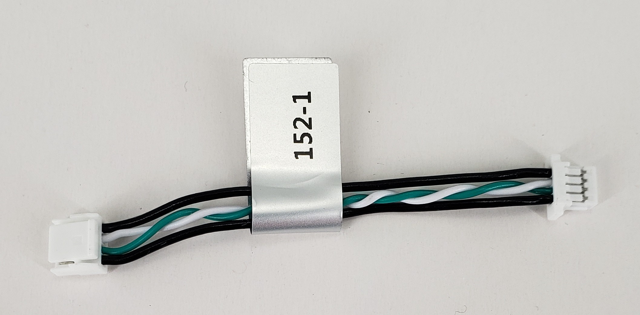
Description:
- 4pin-JST GH to 4pin-JST SH cable (straight thru: 1:1)
- Designed for USB2 Conversion from GH ModalAI Format to SH
Where Used:
- Any ModalAI JST 4-pin USB2 port that is required to slim down to a JST SH
Details:
| Component | Details |
|---|---|
| Connector A | JST, GHR-04V-S |
| Connector B | JST, SHR-04V-S-B |
| Length | 50mm |
| Insulator | PVC |
| Color | Black, White/Green TP |
| Gauge | 26AWG VBUS/GND, 28AWG Twisted Pair Signals |
| Weight | 0.6 grams |
Pinout:
| A | B | ||
|---|---|---|---|
| 1 | VBUS | 1 | VBUS |
| 2 | D- | 2 | D- |
| 3 | D+ | 3 | D+ |
| 4 | GND | 4 | GND |
Pinout, Part Number, & Additional Specs: See Drawing Here Contact ModalAI on the Forum for .DXF or .DWG formats of these drawings.
MCBL-00159

Description:
- Molex Mini-SPOX 4-Pin Power Module Format Power Cable to Doodle Labs 6-pin JST GH Format
- Designed for powering the Doodle Labs RM-2025-62M3 when also using a data-only USB2 cable such as MCBL-00162-1
Where Used:
- Useful for Doodle Labs or other JST 6-Pin High Current modes with 3 conductors for 5V from ModalAI’s power module, M0041.
Details:
| Component | Details |
|---|---|
| Connector A | Molex, 0050375043 (Power Module side, 2 wires) |
| Connector B | JST, GHR-06V-S |
| Length | 100mm |
| Insulator | PVC |
| Color | Black |
| Gauge | 20AWG to 26AWG |
| Weight | 2.1 grams |
Pinout:
| A | B | ||
|---|---|---|---|
| 1 | VDC (Source) | 1, 2, 3 | 5V DC (Load) |
| 2 | GND | 4, 5, 6 | GND |
| 3 | - | - | - |
| 4 | - | - | - |
Pinout, Part Number, & Additional Specs: See Drawing Here Contact ModalAI on the Forum for .DXF or .DWG formats of these drawings.
MCBL-00160
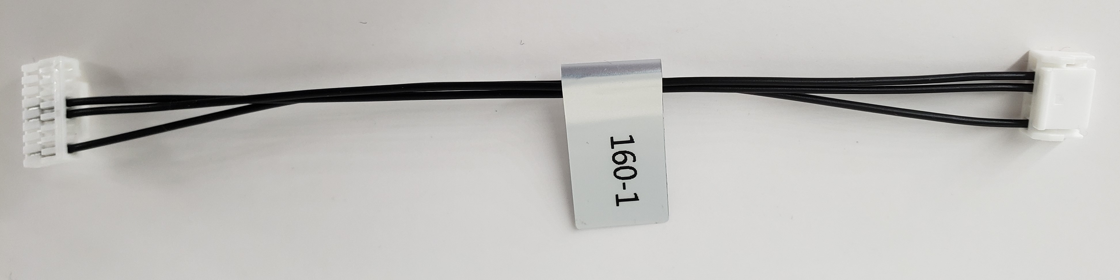
Description:
- VOXL 2 Mini 8-Pin JST GH to DroneCode Compliant UART Port, 6-pin JST GH
- TX/RX/GND Only
Where Used:
- Any VOXL 2 Mini based system where a DroneCode compliant UART device is needed from J10 when in UART mode (not SPI mode)
Details:
| Component | Details |
|---|---|
| Connector A | JST, GHR-08V-S |
| Connector B | JST, GHR-06V-S |
| Length | 100mm |
| Insulator | PVC (flexible) |
| Color | Black |
| Gauge | 28AWG |
| Weight | 0.8 grams |
Pinout:
| A | VOXL 2 MINI | B | Device |
|---|---|---|---|
| 1 | - | - | - |
| 2 | - | - | - |
| 3 | - | - | - |
| 4 | UART_TX_OUT | 3 | UART_RX_IN |
| 5 | UART_RX_IN | 2 | UART_TX_OUT |
| 6 | - | - | - |
| 7 | - | - | - |
| 8 | GND | 6 | GND |
Pinout, Part Number, & Additional Specs: See Drawing Here Contact ModalAI on the Forum for .DXF or .DWG formats of these drawings.
MCBL-00162
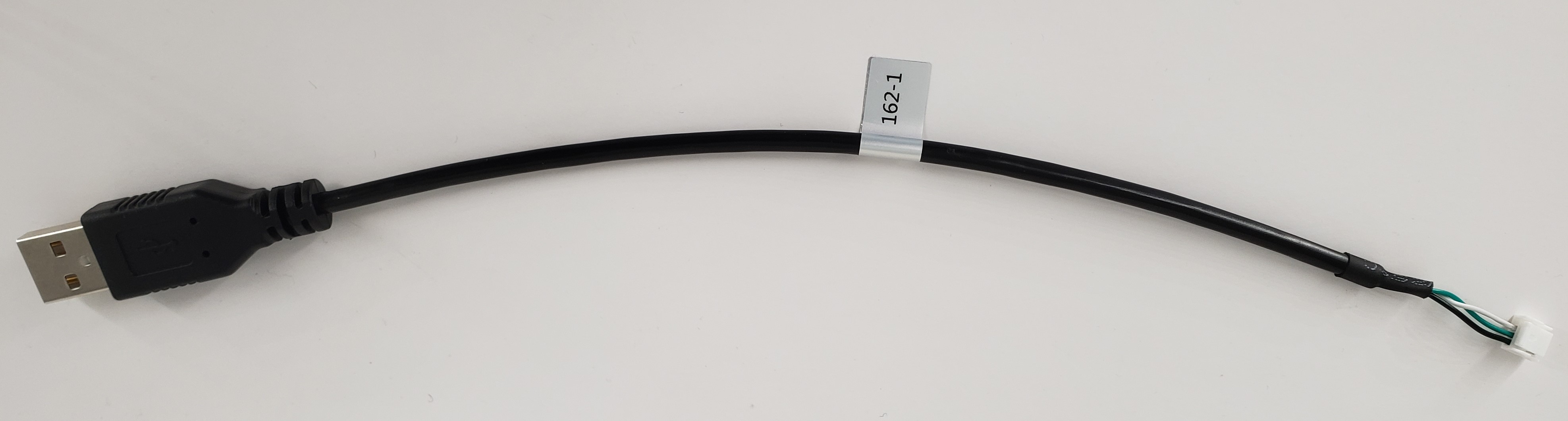
Description:
- USB2 Type-A Plug to 4-pin JST GH Peripheral Data Only Cable
- Designed for a data-only USB2 solution such as a Doodle Labs RM-2025-62M3 when a Type-A Female is present on the host
- NO VBUS, Data +/- and GND Only. This solution expects the USB peripheral is powered independantly from USB, such as with MCBL-00024-1, MCBL-00159-1, or the like.
Where Used:
- Useful for a variety of USB peripherals that are self powered and need a host connection with a USB-A port
- Do not confuse this with MCBL-00104 for Boson which picks up VBUS for configuration purposes, this is just DATA ONLY in a 4-pin GH format
Details:
| Component | Details |
|---|---|
| Connector A | USB, Type A Male |
| Connector B | JST, GHR-04V-S |
| Length | 200mm |
| Insulator | PVC |
| Color | Black, White/Green TP |
| Gauge | 26AWG GND, 28AWG Twisted Pair Signals |
| Weight | 11.7 grams |
Pinout:
| A | B | ||
|---|---|---|---|
| 1 | VBUS | 1 | - |
| 2 | D- | 2 | D- |
| 3 | D+ | 3 | D+ |
| 4 | GND | 4 | GND |
Pinout, Part Number, & Additional Specs: See Drawing Here Contact ModalAI on the Forum for .DXF or .DWG formats of these drawings.
MCBL-00211
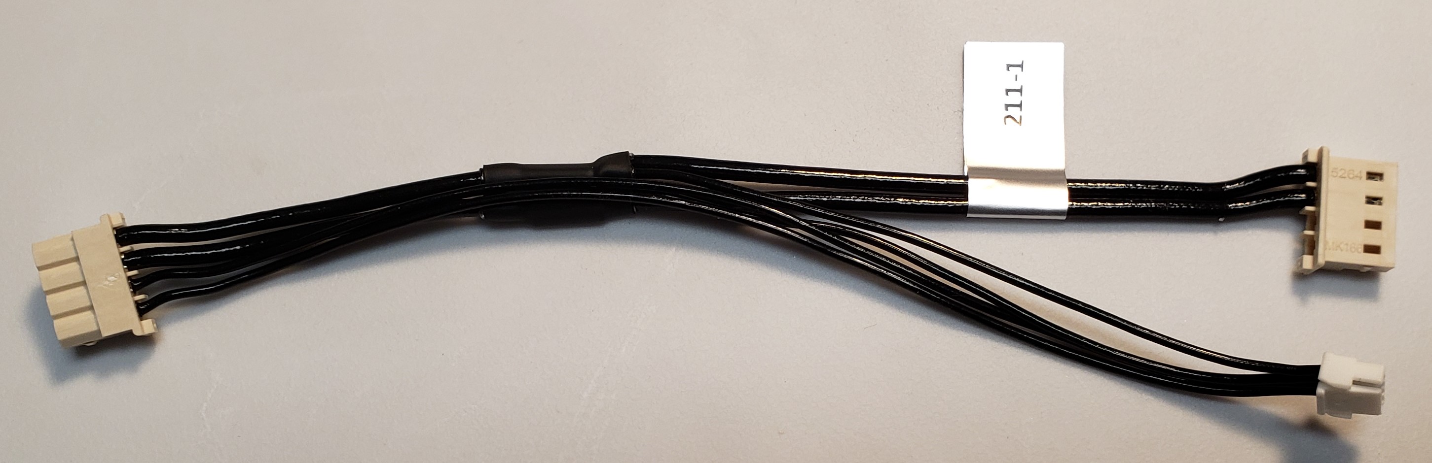
Description:
- VOXL-PM-Y for FCv2 Flight Deck
- Powers both VOXL and FlightCoreV2 from one Power Module, with the I2C bus for power monitoring going to FlightCoreV2
Where Used:
- VOXL-m500
- VOXL J1 + Flight Core V2 J13to VOXL PM v3
Details:
| Component | Details |
|---|---|
| Connector A | Molex, 0050375043 (Power Module side, 4 wires) |
| Connector B | Molex, 0050375043 (VOXL side, 2 wires) |
| Connector C | JST, GHR-04V-S (Flight Core side, 4 wires) |
| Length | 120mm |
| Insulator | PVC (flexible) |
| Color | Black |
| Gauge | 20AWG (A-to-B)/ 26AWG (A-to-C) |
| Weight | 4.0 grams |
Pinout:
| A | VOXL PM | B | VOXL | C | Flight Core V2 |
|---|---|---|---|---|---|
| 1 | 5V DC (Source) | 1 | 5V DC (Load) | 1 | 5V DC (Load) |
| 2 | GND | 2 | GND | 2 | GND |
| 3 | SCL | - | - | 3 | APM_I2C3_SCL_5V |
| 4 | SDA | - | - | 4 | APM_I2C3_SDA_5V |
Pinout, Part Number, & Additional Specs: See Drawing Here Contact ModalAI on the Forum for .DXF or .DWG formats of this drawing.
MCBL-00218
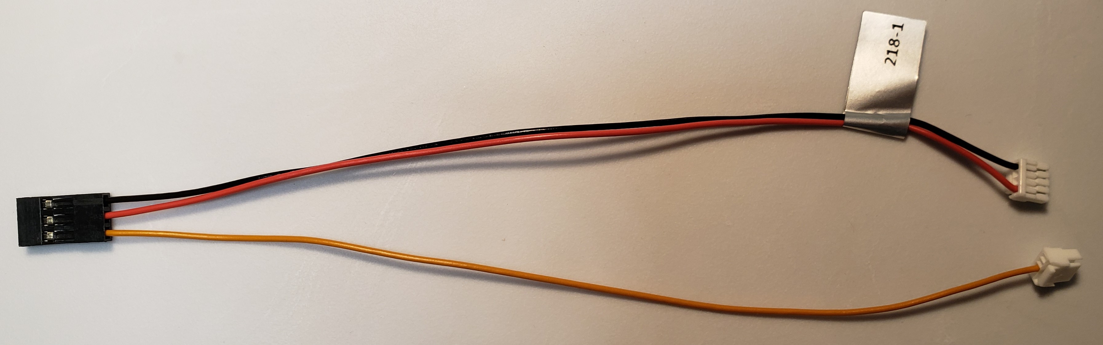
Description:
- RC Input (S.Bus, FrSky)
- Picks up Power on Red+Black, and Receive Signal on Orange from FlightCoreV2 to a R/C receiver 3-pin 0.1” hobby format
- ModalAI conforms to the notion of Pin 1 = Signal, Pin 2 = 5V, & Pin 3 = GND for the 3-pin hobby format. Please notify us if you see anything here to the contrary.
- Note: This is only intended for R/C receivers and cannot power high current servos or BLDCs
Where Used:
- Power 4-pin JST (connector B): Flight Core V2 J8 and R/C signal 4-pin JST (connector C): Flight Core J12 to 3-pin Harwin M20 Receptacle (connector A) to RC Receiver (e.g. S.Bus/FrSky)
- Note: This is not for Spektrum, which requires +3.3V. For Spektrum, please see MCBL-00005
| Component | Details |
|---|---|
| Connector A | Harwin M20-1060300, CONN RCPT HSG 3POS 2.54mm |
| Connector B | JST GHR-04V-S, for +5V Power/GND |
| Connector C | JST GHR-04V-S, for UART_RX signal, +3.3V levels |
| Length | 150 mm |
| Insulator | PVC (flexible) |
| Color | Red/Black/Orange |
| Gauge | 26 AWG |
| Weight | 1.7 grams |
Pinout:
| A | RC Receiver | B | Power | C | R/C Signal |
|---|---|---|---|---|---|
| 1 | S.Bus/DSMX (Orange) | 3 | S.Bus/DSMX (Orange) | ||
| 2 | 5V DC (Load) | 1 | RED (5V, Source) | ||
| 3 | BLACK (GND) | 4 | GND |
Pinout, Part Number, & Additional Specs: See Drawing Here Contact ModalAI on the Forum for .DXF or .DWG formats of this drawing.
MCBL-00221
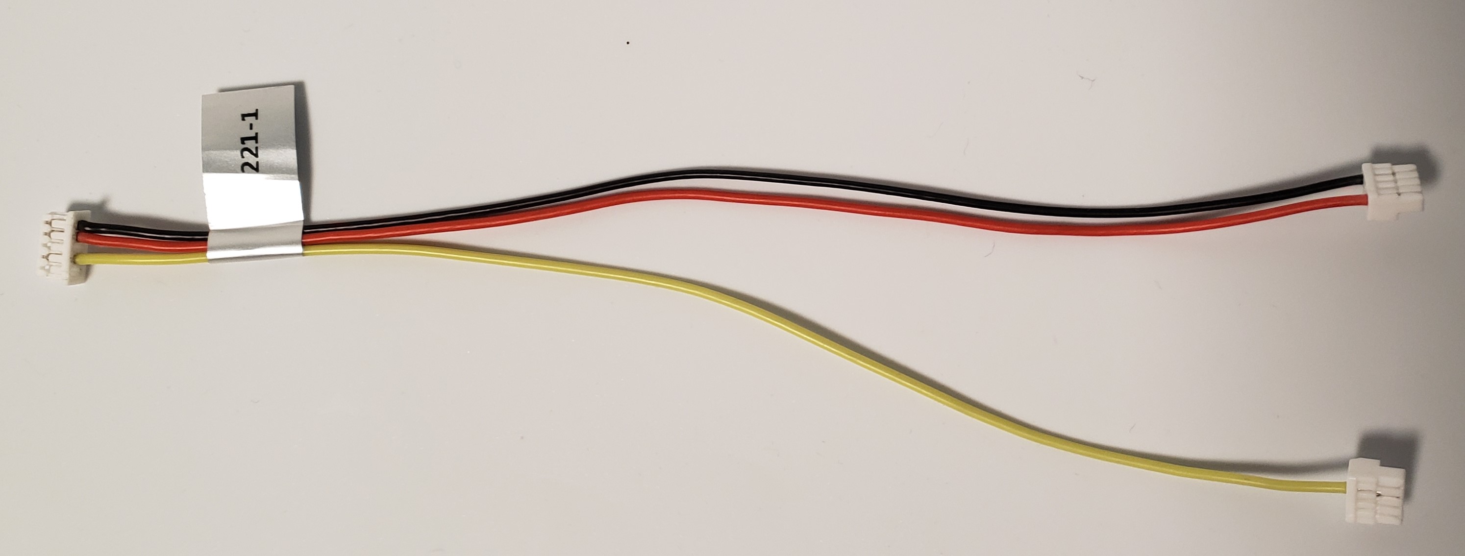
Description:
- RC Input (FrSky R-XSR)
- Picks up Power on Red+Black (from CANBUS port), and Receive Signal on Yellow (R/C Port) from FlightCoreV2 to FrSky R-XSR format R/C receiver 5-pin Picoblade format
- Note: This is just like MCBL-00021 but for FlightCoreV2 instead of FCv1
Where Used:
- 4-pin JST (connector B, yellow cable): Flight Core V2 J12 and 4-pin JST (connector A, Red+Black cables): Flight Core V2 J8 to 5-pin Molex Picoblade (connector C) to FrSky R-XSR Receiver
- Note if CONA and CONB are installed in the wrong/swapped ports on FCv2, damage should not occur due to the FrSKy receiving 3.3V instead of 5V, but the UART TX of the FrSky might be over-driven by the CANBUS transceiver damaging your receiver. Please install connectors carefully.
| Component | Details |
|---|---|
| Connector A | JST GHR-04V-S, for +5V Power/GND |
| Connector B | JST GHR-04V-S, for UART_RX signal, +3.3V levels |
| Connector C | Molex 0510210500, 5-position Picoblade housing 1.25mm |
| Length | 140 mm |
| Insulator | Silicone |
| Color | Red/Black/Yellow |
| Gauge | 26 AWG |
| Weight | 1.3 grams |
Pinout:
| A | Power | C | RC Receiver | B | Signal |
|---|---|---|---|---|---|
| 1 | RED (5V, Source) | 4 | 5V DC (Load) | ||
| 2 | 2 | S.Bus (Yellow) | 3 | S.Bus (Yellow) | |
| 3 | |||||
| 4 | BLACK (GND) | 5 | GND |
Pinout, Part Number, & Additional Specs: See Drawing Here Contact ModalAI on the Forum for .DXF or .DWG formats of this drawing.