Cable User Guides
This section is meant to help users with finding cables, understanding various pinouts, and how to make your own cables from stock you may already have. Once a cable is made for sale and included in various kits, we will show all the relevant specifications (pinouts, BOM, length, etc) on the main datasheets page here
New in this section is a brief user guide on how to use the M0163 JST Flexi-Adapter CCA. This is a powerful new CCA we have to enable converting the most common 4-pin and 6-pin JST GH cables into other 4-pin or generic formats with user-defined pinouts.
Table of contents
Comprehensive ModalAI Cable Spreadsheet and Examples
The spreadsheet file linked Here (Native Microsoft Excel format) is provided as a convenience for all customers to help find and understand the various cables we offer. It even includes information on cables that are EOL/Obsoleted, and cables in-the-works to hopefully give you a jump start.
Latest Spreadsheet Update: V4 on 12/19/23
- File updates (compared to V3):
- Added many new cables since MCBL-00083, plus several new “dash” numbers to existing cable products for length variations.
Don’t have MS Excel? We have verified the key “data filter” function works on the following two programs:
- Linux/Mac user: “OfficeOnly-DekstopEditors”
- Windows user: “Trio Office: Docs & Sheets Software”
Below are some examples how to use this file, most of which is by using the filter pull-down arrows on the top/header row.
Simple Usage: use the top row to sort and filter by the following attributes: 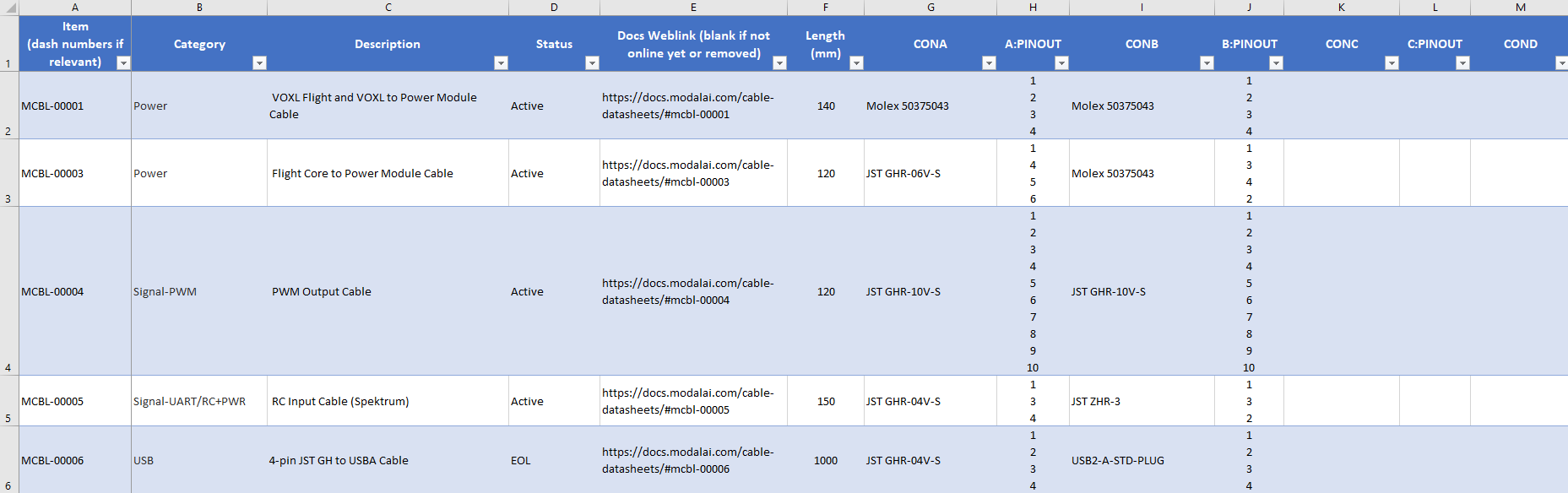
- ModalAI Item/Part Number (Default sorting order provided in the file)
- Cable Category/Type (signal, Power, USB, etc)
- Description
- Status (Active, EOL, In Development, Obsolete)
- Length (in mm): Note: Length refers to the cable conductor length measured from end-to-end, excluding any plastic shroud dimensions. This may not be provided for cables with three or more connectors if it not useful, in which case, please refer to the drawings)
- CONA (connector A manufacturer and MPN)
- CONB (connector B manufacturer and MPN)
- CONC/COND (if applicable)
There is no convention for CONA vs CONB always being a specific type or function, so when searching for specific connector MPNs, be sure to include both ends in the A and B columns (example shown below).
User Example 1: Find a cable by Connector Mates
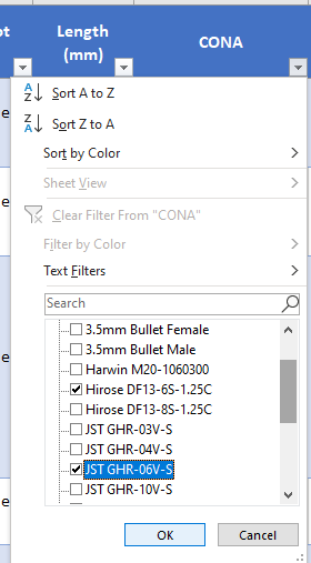
Let’s say you want to find a cable that adapts a Hirose DF13-6S to a JST GHR-06. To find those relevant cables, start by clicking on the down arrow in the “CONA” column, de-select all items, and just select the “Hirose DF13-6S-1.25C” box and the “JST GHR-06V-S” box as shown here:
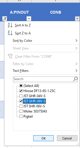
Next, repeat that same step on the CONB filter arrow (note there are now already less options to deselect) as shown here:
After this, you’ll notice the entire file has been filtered to just about six cable options showing all cables that mate DF13-6 to JST GH-6 (and JST to JST along with DF13 to DF13), as shown:
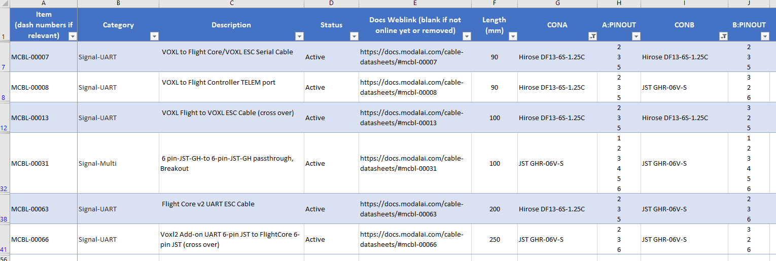
Now, with this info, you can follow the web-links provided to bring you to the TechDocs section of our website that will provide you with further information, including drawings to confirm if these work for you. If you need to validate the pinouts, see the next example:
User Example 2: Determining the Pinouts Portrayed in the file
Once you think you found a cable that meets your length, connector, or function type, the pinouts are the next important function to confirm. The pinouts are listed in this file in a sentence-line aligned format. That is, the order (from top to bottom) the pin numbers are listed in the cell matter. The image below shows some of the more complex pin assignments to see how this works:
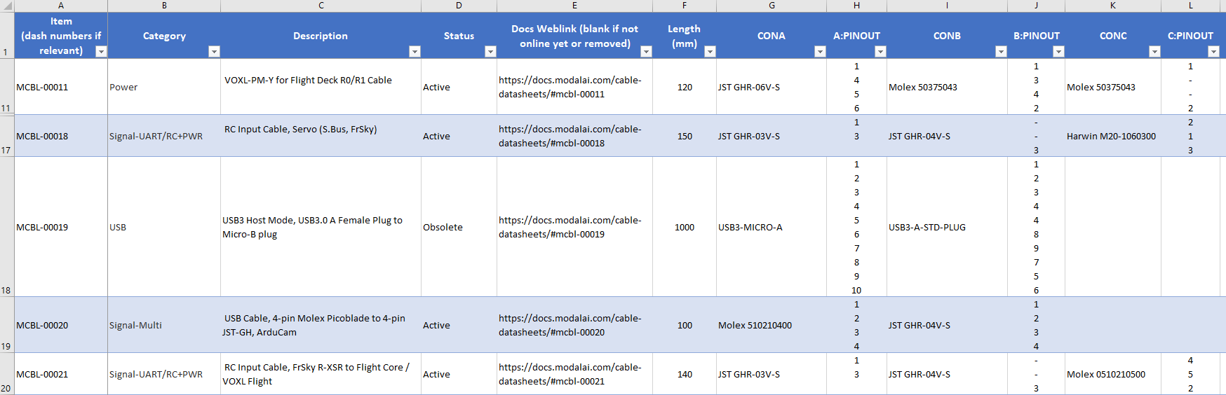
Start on the MCBL-00020, and note that the A:PINOUT and B:PINOUT show “1,2,3,4” and “1,2,3,4” respectively. This means that this is a 1:1 cable, so that pin1 of CONA connects to pin1 of CONB, and so on.
Now, look at the MCBL-00011, and note that the A:PINOUT and B:PINOUT have 4 items, with mapping 1-1, 4-3, 5-4, and 6-2. Also note there is a CONC in this assembly. On that entry for C:PINOUT we see 1, -, -, 2. What this means is that pin1 connects to pin1 of BOTH CONA and CONB, but pin2 of CONC connects to pin6 of CONA, and pin2 of CONB. Note the “dashes”. This shows that nothing on CONC connects to CONA/CONB pins 4-3, and the 5-4 connections.
Another example is on MCBL-00021, where you can see that pin1 of CONA does NOT connect to CONB, but connects to pin4 of CONC, and pin3 of CONB connects to pin2 of CONC, and there are no connections between CONA and CONB.
It can be a little bit of an eye strain at first, but once you follow through a few examples, this becomes easy and natural. And, of course, please contact us on the Forum and we will help you if you have any questions!
We take pride in providing all the information needed to propel your projects to success. We will update this file very frequently in the up-coming months, so check back often and look for the version/date codes so you can see if there are any updates. For now, there will not be a “change log” as it is a simple spreadsheet file maintained manually, so for updates, you may need to run your own diff utility if it is not obvious.
How to Modify MCBL-00022-2 for use with VOXL 2 Mini USB 3 Speeds
This document provides a step-by-step guide of how to take an existing MCBL-00022-2 and add series AC caps enabling VOXL 2 Mini to work with USB 3 speeds. Please reach out to us on the Forum if there are any questions or difficulties performing this rework. We hope to get this listed as a product on our webstore in the up-coming months.
FlightCore V2 Conversion Cables Info
As we update our website and tech docs with more info for FlightCore V2, we know some “power users” are comfortable making their own cable adapters. This section will help guide users that are switching from FCv1 to FCv2 make some of the basic conversion cables. We know it’s a little terse below as we focus instead on making new cable drawings to better document all these cables going forward. If you cannot follow these instructions, please post on the Forum and we will help you out!
Upgrade Path (Compatibility Drawing) Primary UART Link Cable Options:
Not all the cables in the images are listed here yet or on our sales pages, but will be soon! Please reach out to us on the Forum if you need immediate sales/shipping access to these planned cables, and we will accommodate you. You can also see the tips in this section below to guide making your own cables while we get everything posted.
The following image is attempting to show what cables change for the UART/ESC/TELEM links between various systems as a user upgrades from Voxl1 or FlightCore V1 to Voxl2 or FlightCore V2. Please download ESC-UART Cable Guide Here as it is easier to see the details. This does not show all the other power and accessory cables, since those are much easier to scan our site to find, and many of them do not change between generations. We know the cables and connectors on our designs are hard to keep track of, so we hope this helps!
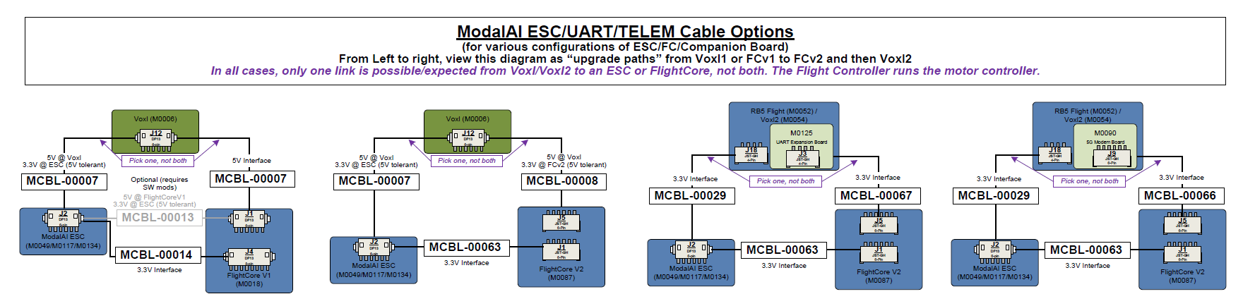
The STM32 has very specific parameters to allow 5V tolerance on UART RX pins. In the diagram above, for FCv2, we meet that constraint. However, if a customer uses a custom config, be sure to check all specs.
Recommended Parts to Order:
Several parts below can be found in kits from Amazon or other large retailers, but they are most commonly knock-offs. Be sure your parts are genuine or you may have some issues following these guides and experience reliability problems long-term.
- 6-position JST GH Shrouds, Digikey Link Here
- 4-position JST GH Shrouds, Digikey Link Here
- Pre-crimped JST GH Pin Contact (SSHL-002T-P0.2) Jumper cable (gives you two contacts per cable, ideal for splicing, can also get in shorter lengths), Digikey Link Here
Tips for making cables:
Get a good set of ESD safe tweezers.
Use a well-lit area with a magnifying glass (helps you find the very small pin 1 arrows or notches).
Plan to discard the old plastic shrouds/housing when re-pinning connectors:
- When taking an existing JST/Hirose/0.025” pin header pin from a shroud, it is important to salvage the pin contact and the integrity of the “barb” that latches into the plastic housing. Therefore, we recommend using tweezers and flipping up the plastic tab that the barb grabs onto, and deliberately damage the plastic shroud that is being replaced anyway. If you press into the crimp terminal to push the barb down, it is required to then pry it back up, which adds a micro-fracture and stress crack into the metal crimp terminal. Crimp tools are expensive (so buy the pre-crimped wires posted above) and soldering is annoying and can be unreliable. Therefore, just toss your old plastic housing when you re-pin anything. Doing this will ensure the maximum integrity of the crimp terminal and wire connection to the housing.
Cables that work the same as FCv1:
MCBL-00004 PWM Output Cable
MCBL-00005 RC Input Cable (Spektrum)
MCBL-00008 VOXL to Flight Controller 2W UART TELEM1 port J1 (Dronecode Compliant, can be ESC or MAVLINK, SW Depending)
- Note, Voxl J12 is a 5V bus. FCv1 J1 is also a 5V bus. However, FCv2 J1 port is a 3.3V bus to be in-line with Dronecode, but it is 5V Tolerant due to buffers on J1. All other FCv2 ports are NOT 5V compliant since they are direct to the MCU which has an ABS max of 4.0V on all signal pins. There are a few noted exceptions as shown in the diagram above. Most of the Receive UART pins are 5V tolerant, but the receive buffers on the other side loose a lot of noise margin. It gets complicated really fast parsing through the MCU datasheet and running PX4 on-top. Always reach out if you need more info.
- The other two 6-pin DF13 ports on Voxl (J10, J11) are 3.3V signal levels, and therefore with MCBL-00008, can connect to FCv2 J1 or J5.
MCBL-00009 4-pin JST to micro USB Female/Receptacle Cable
MCBL-00028-2 Seeker GPS Cable
Cables Already in Process on ModalAI.com, but you can get a jump start if you want:
This tutorial Here is a great step-by-step with detailed photos showing how to make an MCBL-00061 from an MCBL-00015. Once you have reviewed this tutorial, any of the changes shown below should be easy to follow, understand, and replicate as you need!
The format here is showing how to make a new cable from an existing one (Existing -> New) by swapping out a few shrouds and re-pinning them.
MCBL-00003 → MCBL-00062 (Standalone power from APM)
- From MCBL-00003
- Keep Molex Mini-Spox side
- Change JST 6-pin to JST 4-pin GHR-04V-S as follows:
- pin 1 of Molex to pin1 of 4-pin JST, 2:2, 3:3, 4:4
- Power plugs into M0087 J13 (Might be RED)
MCBL-00011 → MCBL-00211 (APM to Voxl/Voxl2 + FCv2)
- From MCBL-00011
- Keep Both Molex Mini-Spox sides
- Change JST 6-pin to JST 4-pin GHR-04V-S as follows:
- pin 1 of Molex to pin1 of 4-pin JST, 2:2, 3:3, 4:4
- Power plugs into M0087 J13 (Might be RED)
FrSKY/S.BUS 5V RC Cables: On FCv1, 3-pin JST for J9 now moves to a 4-pin JST J8 (CANBUS Port) since that is the only “free” +5V source easily picked up
MCBL-00018 → MCBL-00218 ( FCv2 RC Input (S.Bus, FrSky))
- From MCBL-00018
- Keep 3-pin Harwin Socket and 4-pin JST (with the single wire)
- Change 3-pin JST red/black to 4-pin JST GHR-04V-S as follows:
- Pin 1 stays to Pin 1
- Pin 2 and now Pin 3 stay empty on the new 4-pin
- Pin 3 moves to pin 4 (GND)
FrSKY/S.BUS 5V RC Cables: Switching from FCv1 to VOXL2 I/O (M0065) to effectively make MCBL-00064
MCBL-00018 → MCBL-00064 ( FCv2 RC Input (S.Bus, FrSky))
- From MCBL-00018
- Keep 3-pin Harwin Socket and 4-pin JST (with the single wire)
- Keep Pin 1 of Harwin Socket to Pin 3 of 4-pin JST (Signal)
- Remove (and discard) 3-pin JST housing. Red and black cables remap to the 4-pin JST as follows:
- Pin 1 of the 3-pin JST now moves to Pin1 of the 4-pin JST (+5V)
- Pin 3 of the 3-pin JST now moves to Pin4 of the 4-pin JST (GND)
MCBL-00021 → MCBL-00221 ( FCv2 RC Input (FrSky R-XSR))
- From MCBL-00021
- Keep 5-pin Picoblade socket and 4-pin JST (with the single wire)
- Change 3-pin JST red/black to 4-pin JST GHR-04V-S as follows:
- Pin 1 stays to Pin 1
- Pin 2 and now Pin 3 stay empty on the new 4-pin
- Pin 3 moves to pin 4 (GND)
MCBL-00029 → MCBL-00063-1 ( FCv2 to ModalAI ESC, 200mm)
- From MCBL-00029
- Keep the Hirose DF13 side
- Change JST 4-pin to JST 6-pin GHR-06V-S as follows:
- Pin 2 and Pin 3 of 4-pin move to pin 2 & pin 3 of 6-pin.
- Pin 4 GND of 4-pin to pin 6 GND of 6-pin JST
MCBL-00008 → MCBL-00063-2 ( FCv2 to ModalAI ESC, 90mm)
- From MCBL-00008
- Keep the Hirose DF13 side
- Repin the JST 6-pin to swap pins 2&3:
- Pin 2 and Pin 3 of 6-pin JST swap positions in the housing.
- Note, it might be OK to keep this housing if you replace them carefully, otherwise, you should plan on replacing the housing as per our standard recommendations.
- In the case of housing replacement, be sure to keep Pin 6 in the same Pin 6 location along with the 2 swaps noted above.
M0163 JST FLEXI-Adapter User Guide
Our new M0163 circuit board is designed to cover a lot of the common annoyances with various 6-pin and 4-pin JST cables. We designed this adapter as a very fast and easy way to use a single MCBL-00091 USB to Serial FTDI Console cable MCBL-00091 Link Here and switch between the M0129 Mini ESC port J1 (to run ESC programming and test tools) or to easily swap RX/TX and connect to VOXL 2 ESC port J18 for Hardware In The Loop (HWIL/HIL) simulation. We also added a few extra features such as converting 6-pin JST to 4-pin JST or any 4-pin/6-pin conversion by using standard 0.025” square header posts. This section will cover many common scenarios and provide guidance how to use this neat little adapter. But first, download all the design data!!! We are making the Schematic, Assembly, and 3D step available to help you use this neat tool:
M0163 Design Collateral
Please dig into the schematic to understand how to use this tool. If you are having any difficulties reading that or understanding some of these examples, please reach out to us on the Forum and be sure to mention the M0163 or this page.
M0163 User Examples
M0163 4-pin JST to 4-pin JST Straight Through Example
In this example, let’s say you are running ESC Tools on the M0129, and you bought an MCBL-00091. Normally, there is nothing to do. MCBL-00091 can plug directly into M0129 J1. But, if you wanted to probe the UART lines, then this adapter will help by exposing them on the 4-position jumper block. In this case, you want to follow the image shown here, where the 4-jumpers are bridging the pins 1-2, 3-4, 5-6, and 7-8 as shown. We use RED and BLUE on purpose here to track the changes later on:
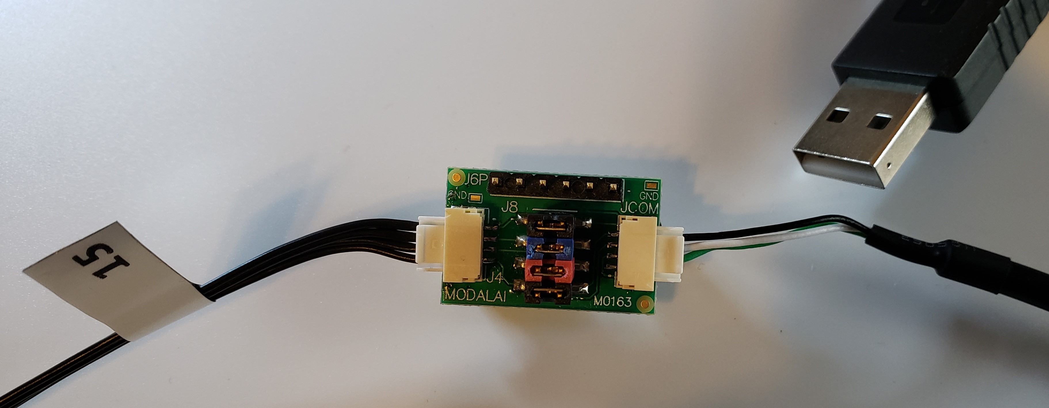 This example shows how an MCBL-00015 Link Here would be needed to connect your ESC (or other 4-pin JST) to the Flexi-Adapter.
M0163 4-pin JST to 4-pin JST Cross-Over Example
In this example, let’s say you bought an MCBL-00091 and want to run HWIL using your VOXL 2. In this case, you need to swap RX/TX pins on MCBL-00091. Instead of re-pinning your serial adapter, all that is needed now is to re-position the jumpers on the jumper block. In this case, you want to follow the image shown here, where the 4-jumpers are bridging the pins 1-2, 3-5, 4-6, and 7-8 as shown. We use RED and BLUE on purpose here to track the changes relative to the straight-thru example above:
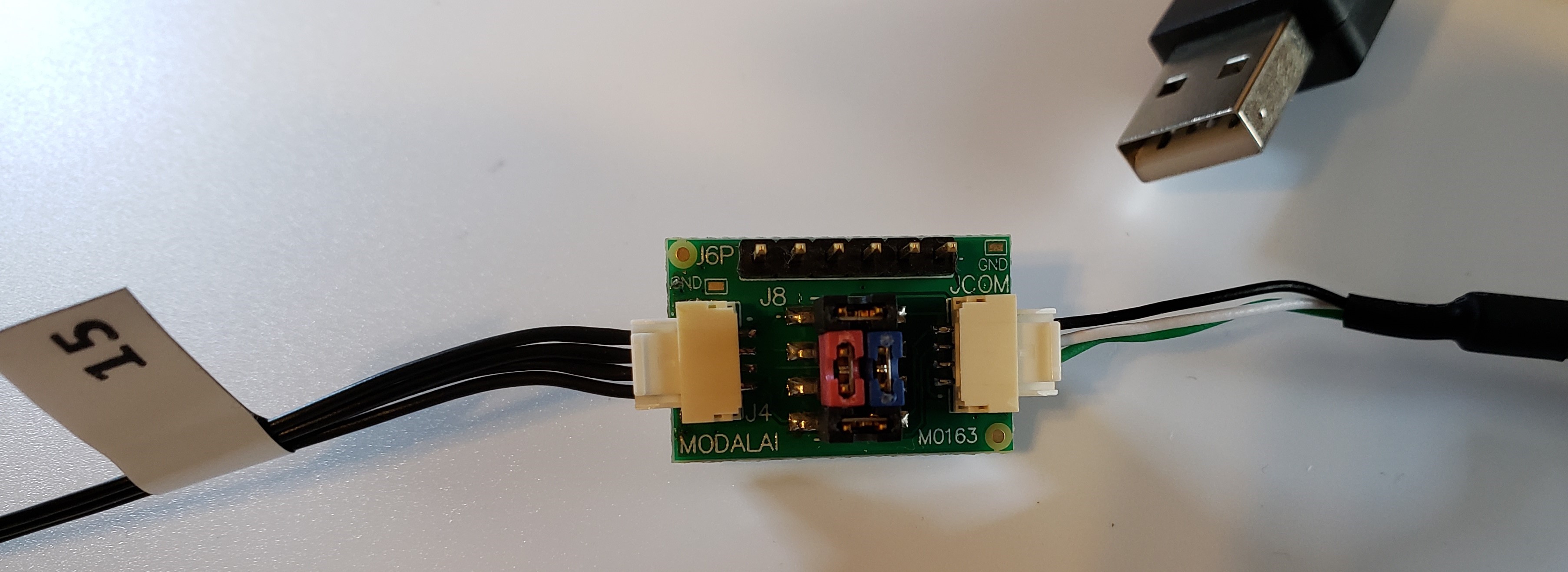 This example shows how an MCBL-00015 Link Here would be needed to connect your VOXL 2 (or other 4-pin JST) to the Flexi-Adapter. Note the RED and BLUE jumpers are now installed rotated.
M0163 6-pin JST to 4-pin JST Straight Through Example
In this example, let’s say you bought a VOXL 2 Developer Test Board or any other ModalAI Hardware with UARTs in the 6-pin format and you need to display that port data to a serial console on your host machine. The Flexi-Adapter was designed with that in mind as well. However, we provide full re-pinning flexibility for any pins on your 6-pin JST to be re-mapped to any of the 4-pins on JCOM. Care must be taken to ensure you do not cross-wire power and ground pins, and that you also provide a common ground connection between all the hardware.
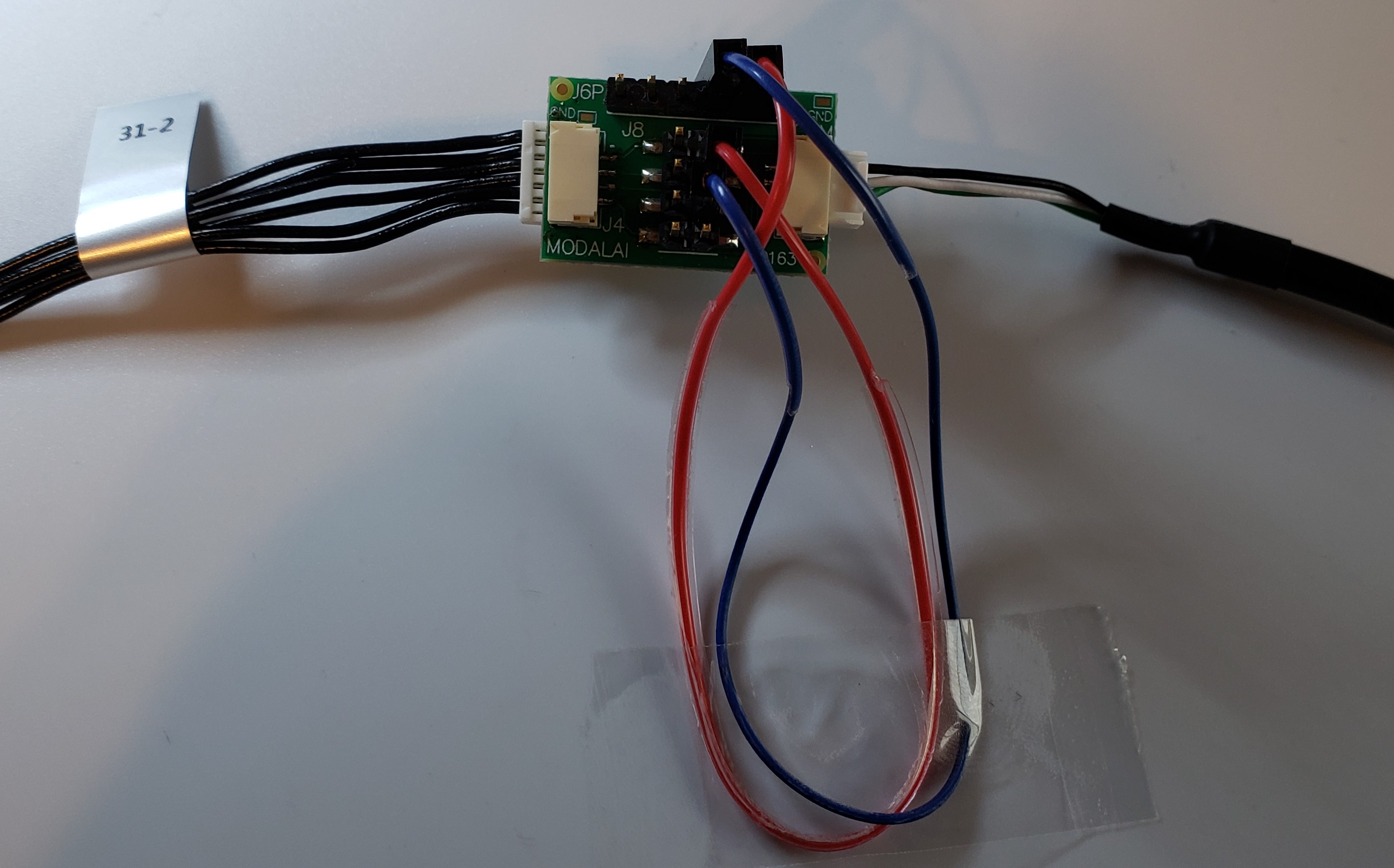 This example shows how an MCBL-00031 Link Here would be needed to connect your 6-pin JST ports to the Flexi-Adapter J6J with pins 2 & 3 aligning as RX/TX. Note the RED and BLUE jumper cables, and in this image we do not show the Ground cable.
M0163 6-pin JST to 4-pin JST Cross-Over Example
In this example, let’s say you bought a VOXL 2 Developer Test Board or any other ModalAI Hardware with UARTs in the 6-pin format and you need to display that port data to a serial console on your host machine, and for whatever reason the mapping is reversed from MCBL-00091. The Flexi-Adapter was designed with that in mind as well. Just like above, any pins on your 6-pin JST can be re-mapped to any of the 4-pins on JCOM. Care must be taken to ensure you do not cross-wire power and ground pins, and that you also provide a common ground connection between all the hardware.
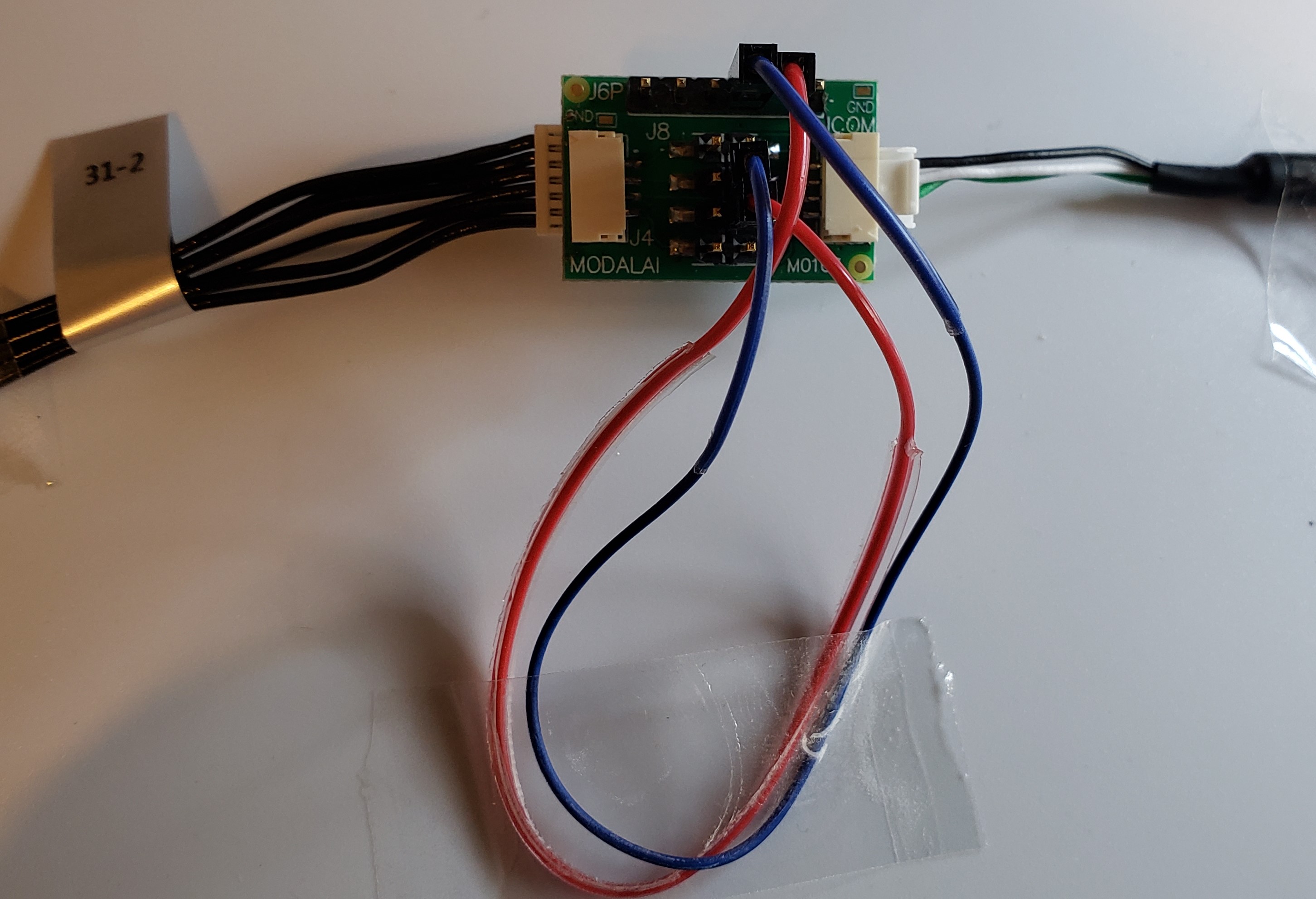 This example shows how an MCBL-00031 Link Here would be needed to connect your 6-pin JST ports to the Flexi-Adapter J6J with pins 2 & 3 aligning as TX/RX. Note the RED and BLUE jumper cables crossed from above, and in this image we do not show the Ground cable.
M0163 6-pin JST to 4-pin JST Adapter
In this example, You can effectively convert a 6-pin JST to a 4-pin JST with any pinout you wish. This is where your imagination can really go wild by converting any thing to anything else. Simply connect the 6-pin header pins to the even or odd side of the 2x4 header as needed. The possibilities are endless.
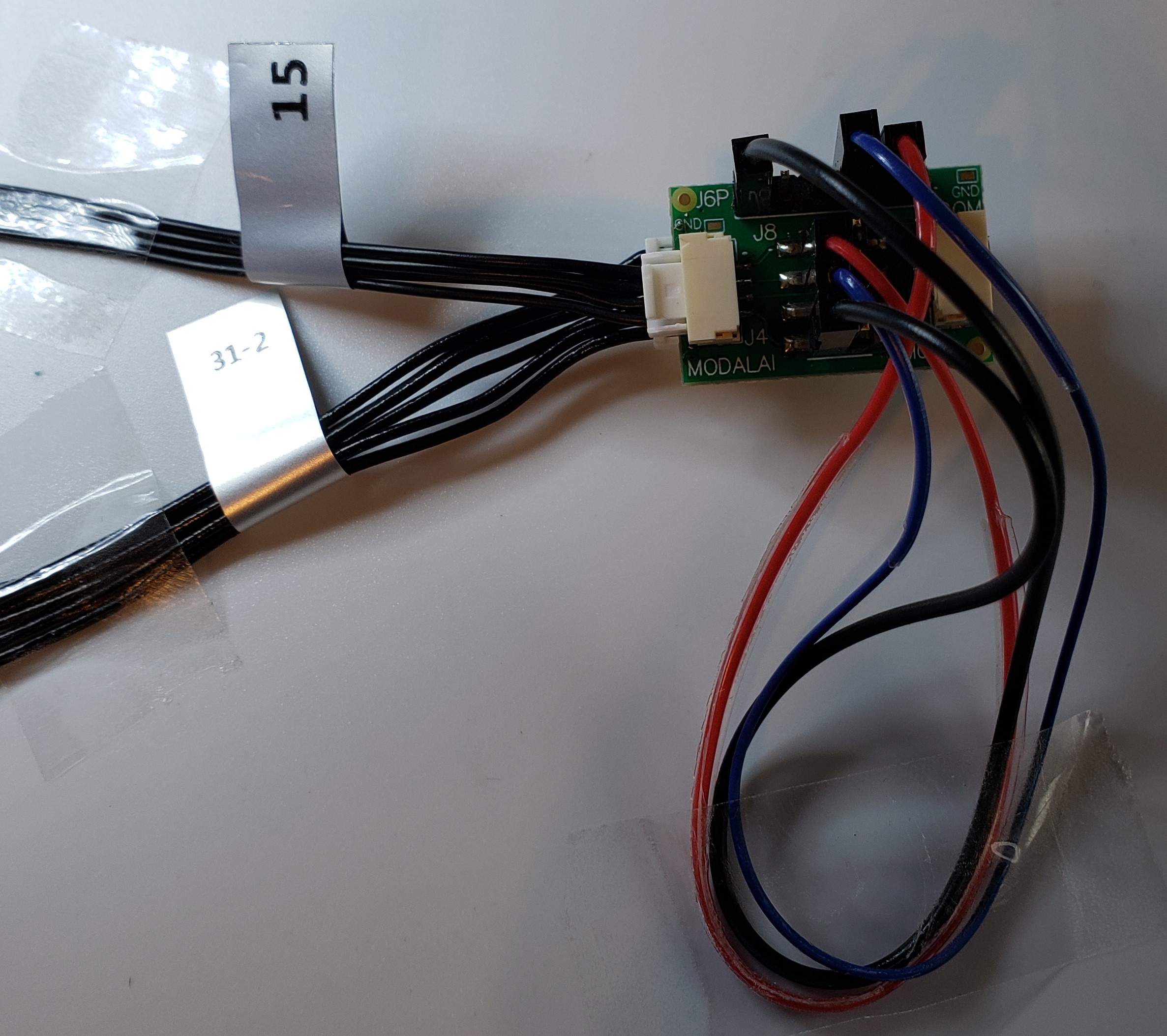 This example shows how an MCBL-00031 Link Here can effectively be connected to an MCBL-00015 Link Here and it is possible with some additional soldering to the jumpers you can create a “Y” cable from the 6-pin to two 4-pins, or any combination thereof.