VOXL Flight Connectors
Note: Due to supply chain issues, the colors of the connectors on VOXL Flight are subject to change. If the colors of the connectors are different, please disregard.
Table of contents
- Board Connections and Pin-out Specifications
- J2 - Hires 4k Image Sensor (CSI0)
- J3 - Stereo or Time-of-flight Image Sensor (CSI1)
- J6 - Cooling Fan Connector
- J7 BLSP6 (I2C) and BLSP9 (UART / SPI): External GPS/MAG
- J13 - Expansion B2B connection
- J14 - Integrated GNSS Antenna Connection
- J1001 - Programming and Debug Console (USART3)
- J1002 - UART ESC, UART2/TELEM3 Interface Connector
- J1003 - PPM RC In
- J1004 - RC input / Spektrum/SBus/USART6 Connector
- J1006 - USB Connector
- J1007 - 8-Channel PWM / 4-Channel DShot ESC Output Connector
- J1008 - CAN Bus Connector
- J1009 - I2C3, UART4
- J1010 - Telemetry Connector (TELEM1)
- J1011 - I2C2, Safety Button Input
- J1012 - External GPS & Mag, USART1, I2C1 Connector
- J1013 - 5V DC Power Input, I2C3 to power cable “APM”
- J4 - Tracking/Optic Flow Image Sensor (CSI2)
- J8 - USB 3.0 OTG
- J10 - UART or I2C off-board (external Sonar or IMU sensor)
- J11 - BLSP12 off-board (SPEKTRUM)
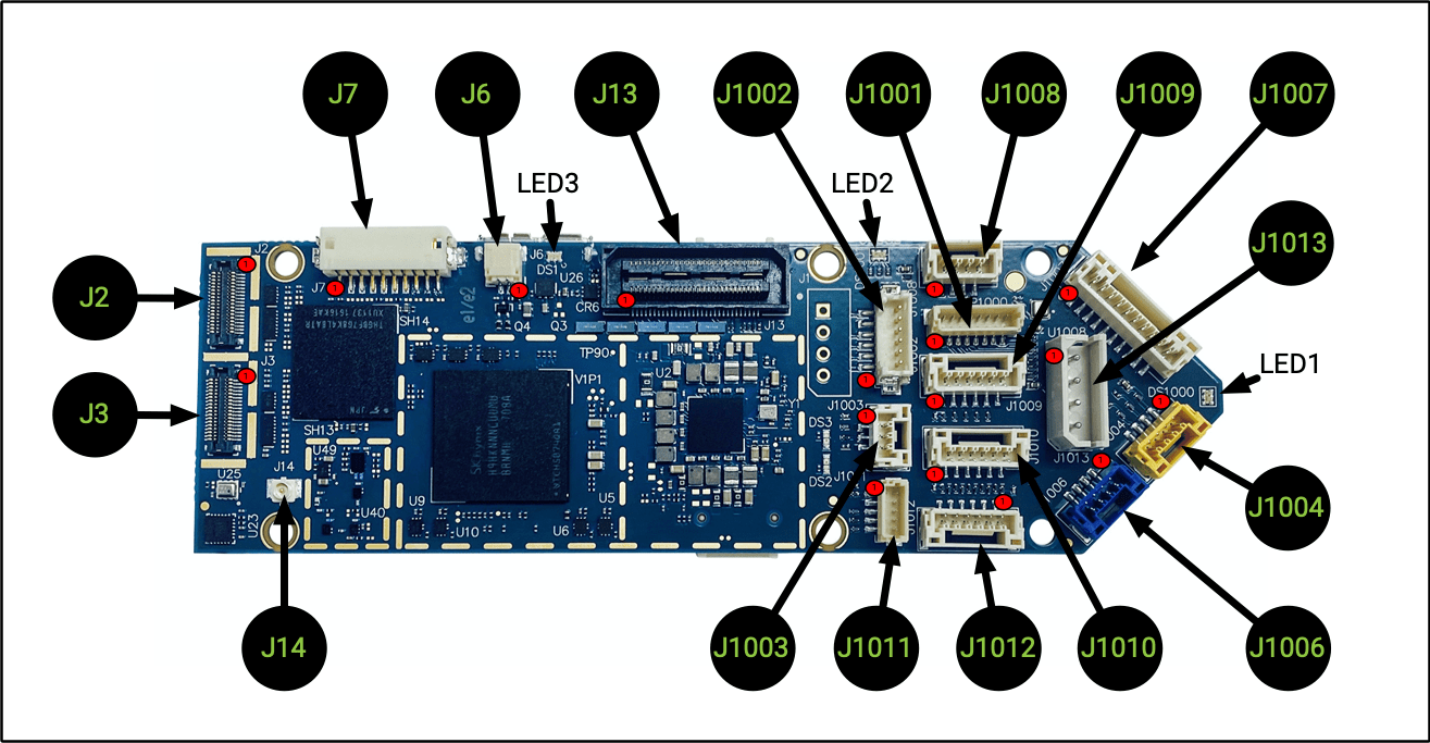
Board Connections and Pin-out Specifications
VOXL Flight Board Top
Note: 1000 Series connectors accessible from the STM32/PX4
| Connector | Summary |
|---|---|
| J2 | Hires 4k Image Sensor (CSI0) |
| J3 | Stereo Image Sensor (CSI1) |
| J6 | Cooling Fan Connector |
| J7 | BLSP6 (GPIO) and BLSP9 (UART) |
| J13 | Expansion B2B |
| J14 | Integrated GNSS Antenna Connection |
| J1001 | Programming and Debug/UART3 |
| J1002 | UART ESC, UART2/TELEM3 |
| J1003 | PPM RC In |
| J1004 | RC Input, Spektrum/SBus/UART6 |
| J1006 | USB 2.0 Connector (PX4/QGroundControl) |
| J1007 | 8-Channel PWM/DShot ESC Output |
| J1008 | CAN Bus |
| J1009 | I2C3, UART4 |
| J1010 | Telemetry (TELEM1) |
| J1011 | I2C2, Safety Button Input |
| J1012 | External GPS & Mag, UART1, I2C1 |
| J1013 | Power Input, I2C3 |
J2 - Hires 4k Image Sensor (CSI0)
| J2 Board Connector | Image Sensor (Flex) Mating Connector |
|---|---|
| Panasonic, MPN: AXT336124 | Panasonic MPN: AXT436124 |
Pin-out:
| Pin # | Signal Name | Pin # | Signal Name |
|---|---|---|---|
| 1 | GND | 2 | GND |
| 3 | VREG_L17A_2P8 (AFVDD) | 4 | CAM0_STANDBY_N |
| 5 | CCI_I2C_SDA0 | 6 | VREG_LVS1A_1P8 (DOVDD) |
| 7 | CCI_I2C_SCL0 | 8 | VREG_L3A_1P1 (DVDD) |
| 9 | CAM0_RST0_N | 10 | CAM_MCLK0_BUFF |
| 11 | GND | 12 | GND |
| 13 | MIPI_CSI0_CLK_CONN_P | 14 | CAM_FLASH |
| 15 | MIPI_CSI0_CLK_CONN_M | 16 | CAM_SYNC_0 |
| 17 | MIPI_CSI0_LANE0_CONN_P | 18 | CAM0_MCLK3 |
| 19 | MIPI_CSI0_LANE0_CONN_M | 20 | VREG_L22A_2P8 (AVDD) |
| 21 | GND | 22 | GND |
| 23 | MIPI_CSI0_LANE1_CONN_P | 24 | CAM_RST1_N |
| 25 | MIPI_CSI0_LANE1_CONN_M | 26 | CAM_SYNC_1 |
| 27 | MIPI_CSI0_LANE2_CONN_P | 28 | CCI_I2C_SDA1 |
| 29 | MIPI_CSI0_LANE2_CONN_M | 30 | CCI_I2C_SCL1 |
| 31 | GND | 32 | GND |
| 33 | MIPI_CSI0_LANE3_CONN_P | 34 | VPH_PWR |
| 35 | MIPI_CSI0_LANE3_CONN_M | 36 | GND |
Supported Sensors
The following sensors are supported on J2 (CSI0):
- IMX214
- IMX230
- IMX377
- IMX378
- OV16825
Supported modules:
| Description | MPN | Link | Datasheet |
|---|---|---|---|
| ModalAI Sony IMX214 wide angle | MCAM-00024 | Buy | Datasheet |
| ModalAI Sony IMX214 | MCAM-00024 | Buy | Datasheet |
| ModalAI Sony IMX377 | MCAM-00026 | Buy | Datasheet |
J3 - Stereo or Time-of-flight Image Sensor (CSI1)
| J3 Board Connector | Image Sensor (Flex) Mating Connector |
|---|---|
| Panasonic, MPN: AXT336124 | Panasonic MPN: AXT436124 |
Pin-out:
| Pin # | Signal Name | Pin # | Signal Name |
|---|---|---|---|
| 1 | GND | 2 | GND |
| 3 | VREG_L18A_2P8 (AFVDD) | 4 | CAM1_STANDBY_N |
| 5 | CCI_I2C_SDA0 | 6 | VREG_S4A_1P8 (DOVDD) |
| 7 | CCI_I2C_SCL0 | 8 | VREG_L3A_1P1 (DVDD) |
| 9 | CAM1_RST0_N | 10 | CAM_MCLK1_BUFF |
| 11 | GND | 12 | GND |
| 13 | MIPI_CSI1_CLK_CONN_P | 14 | CAM_FLASH |
| 15 | MIPI_CSI1_CLK_CONN_M | 16 | CAM_SYNC_0 |
| 17 | MIPI_CSI1_LANE0_CONN_P | 18 | CAM1_MCLK3 |
| 19 | MIPI_CSI1_LANE0_CONN_M | 20 | VREG_L23A_2P8 (AVDD) |
| 21 | GND | 22 | GND |
| 23 | MIPI_CSI1_LANE1_CONN_P | 24 | CAM_RST1_N |
| 25 | MIPI_CSI1_LANE1_CONN_M | 26 | CAM_SYNC_1 |
| 27 | MIPI_CSI1_LANE2_CONN_P | 28 | CCI_I2C_SDA1 |
| 29 | MIPI_CSI1_LANE2_CONN_M | 30 | CCI_I2C_SCL1 |
| 31 | GND | 32 | GND |
| 33 | MIPI_CSI1_LANE3_CONN_P | 34 | VPH_PWR |
| 35 | MIPI_CSI1_LANE3_CONN_M | 36 | GND |
Supported Image Sensors
The following sensors are supported on J3 (CSI1):
- OV7251
- PMD (Infineon)
Supported modules:
| Description | MPN | Link | Datasheet |
|---|---|---|---|
| Stereo Camera Pair for Obstacle Avoidance Kit | MSU-M0015-1-01 | Buy | Datasheet |
| PMD Time of Flight | MKIT-00017-3 | Buy | Datasheet |
J6 - Cooling Fan Connector
Pin Configuration
| Pin # | Signal Name |
|---|---|
| 1 | EXT_FAN_5V |
| 2 | EXT_FAN_RET |
Connector
- J.S.T. Corporation, SM02B-SRSS- TB(LF)(SN)
Mating Connector
VOXL Side:
- J.S.T. Corporation, MPN: SM02B- SRSS-TB(LF)(SN)
Fan Side:
- J.S.T. Corporation
- Connector, MPN: SHR-02V-S
- Connector Contact Pins, MPN: SSH-003T-P0.2-H
Notes
Supported Fan Module:
- DDH Enterprise, Inc, MPN: DDH-2016-013 MCN: 420-59855-0001
J7 BLSP6 (I2C) and BLSP9 (UART / SPI): External GPS/MAG
Pin Configuration
| Pin # | Signal Name | Alt Function |
|---|---|---|
| 1 | VREG_3P3V | |
| 2 | BLSP9_UART_TX_3P3 | GPIO 49 / BLSP9_SPI_MOSI |
| 3 | BLSP9_UART_RX_3P3 | GPIO 50 / BLSP9_SPI_MISO |
| 4 | BLSP6_I2C_SDA_3P3 | GPIO 27 |
| 5 | GND | |
| 6 | BLSP6_I2C_SCL_3P3 | GPIO 28 |
| 7 | BLSP6_AUX2_3P3 | (original docs show GPIO 26, however not functional) |
| 8 | BLSP6_AUX1_3P3 | (original docs show GPIO 25, however not functional) |
| 9 | BLSP9_UART_CTS_N_3P3 | GPIO 51 / BLSP9_SPI_CS_N |
| 10 | BLSP9_UART_RFR_N_3P3 | GPIO 52 / BLSP9_SPI_CLK |
Connector
- HIROSE Electric, MPN: DF13-10P-1.25H
Mating Connector
VOXL Side:
- HIROSE Electric, MPN: DF13- 10P-1.25H
GPS/MAG Side:
- HIROSE Electric, MPN: DF13- 10S-1.25C
Notes
Supported GPS Module:
- MCN: 20-CE766-H1 = CCA, H13931V2, SIRFSTARV CREST BOARD REV2
The above uses antenna:
- TAOGLAS LTD, MPN: CGGBP.25.4.A.02
J13 - Expansion B2B connection
Pin Configuration
| Pin # | Signal Name | Pin # | Signal Name |
|---|---|---|---|
| 1 | GND | 2 | VDCIN_5V_CONN |
| 3 | APQ_GPIO_96 | 4 | VDCIN_5V_CONN |
| 5 | APQ_GPIO_95 | 6 | VDCIN_5V_CONN |
| 7 | APQ_GPIO_94 | 8 | USB2_HS_ID |
| 9 | APQ_GPIO_92 | 10 | GND |
| 11 | GND | 12 | USB2_HS_D_M |
| 13 | BLSP11_0_SCL_GPIO61 | 14 | USB2_HS_D_P |
| 15 | BLSP11_1_SDA_GPIO60 | 16 | USB2_HS_VBUS_CONN |
| 17 | BLSP11_2_RX_GPIO59 | 18 | GND |
| 19 | BLSP11_3_TX_GPIO58 | 20 | APQ_GPIO_64 |
| 21 | GND | 22 | APQ_GPIO_127 |
| 23 | BLSP8_0_SCL_GPIO7 | 24 | APQ_GPIO_126 |
| 25 | BLSP8_1_SDA_GPIO6 | 26 | APQ_GPIO_70 |
| 27 | BLSP8_2_RX_GPIO5 | 28 | APQ_GPIO_71 |
| 29 | BLSP8_3_TX_GPIO4 | 30 | APQ_GPIO_72 |
| 31 | GND | 32 | APQ_GPIO_93 |
| 33 | JTAG_TDO | 34 | APQ_GPIO_91 |
| 35 | JTAG_SRST_N | 36 | GND |
| 37 | JTAG_TCK | 38 | APQ_GPIO_106 |
| 39 | JTAG_TDI | 40 | APQ_GPIO_107 |
| 41 | JTAG_TMS | 42 | APQ_GPIO_108 |
| 43 | JTAG_TRST_N | 44 | GND |
| 45 | JTAG_PS_HOLD | 46 | APQ_GPIO_114 |
| 47 | VREG_S4A_1P8 | 48 | APQ_GPIO_104 |
| 49 | PMIC_RESIN_N | 50 | APQ_GPIO_103 |
| 51 | APQ_RESOUT_N | 52 | APQ_GPIO_102 |
| 53 | VREG_3P3V | 54 | APQ_GPIO_101 |
| 55 | KYPDPWR_N | 56 | APQ_GPIO_57 |
| 57 | VPH_PWR | 58 | GND |
| 59 | GND | 60 | PM8996_GPIOC15 |
Connector
- Samtec Inc., MPN: QSH-030-01-L-D-A-K
Mating Connector
VOXL Side:
- Samtec Inc., MPN: QSH-030-01-L-D-A-K
Debug Board Side:
- Samtec Inc, MPN: QTH-030-02- L-D-A-K
Notes
Supported Debug B2B Module:
- Eagle Nest, MCN: 20-H9420-1
- Serial Feather PRO Edition, MCN: 30-H9916-1
More details are available here.
J14 - Integrated GNSS Antenna Connection
Pin Configuration
- Center Conductor
Connector
- HIROSE Electric, MPN: U.FL-R- SMT-1(10)
Mating Connector
VOXL Side:
- HIROSE Electric, MPN: U.FL-R- SMT-1(10)
GNSS Antenna Side:
- HIROSE Electric, MPN: U.FL-LP
Notes
Supported Module:
- CABLE ASSY, U.FL TO SMA-F BHD, 1.32 MM COAX MCN: CV90-N5175-A4
- Passive antenna configuration (no DC bias)
J1001 - Programming and Debug Console (USART3)
Connector: 8 Position, Vertical, BM08B-SRSS-TB(LF)(SN)
Note: used for PX4 debug console, can be used for STM32 FW update
| Pin # | Signal Name |
|---|---|
| 1 | VREG_3V3 |
| 2 | USART3_2W_DEBUG_TX |
| 3 | USART3_2W_DEBUG_RX |
| 4 | SWDIO |
| 5 | SWCLK |
| 6 | GND |
| 7 | !RESET |
| 8 | VPP_STM |
J1002 - UART ESC, UART2/TELEM3 Interface Connector
Connector: 6 Position DF13, Vertical, DF13-6P-1.25V(50)
Note: 2 wire UART is OK here
| Pin # | Signal Name |
|---|---|
| 1 | 5VDC (other pins are 3.3V, input or output if supplied at another pin) |
| 2 | UART2_4W_RX_3V3 |
| 3 | UART2_4W_TX_3V3 |
| 4 | UART2_4W_RTS_3V3 |
| 5 | GND |
| 6 | UART2_4W_CTS_3V3 |
J1003 - PPM RC In
Connector: 3 Position JST GH, Vertical, BM03B-GHS-TBT
Note: This JST connector is reversed when compared to Flight Core, pinouts are still the same
| Pin # | Signal Name |
|---|---|
| 1 | 5VDC (other pins 3.3V, input or output if supplied at another pin) |
| 2 | PPM_IN |
| 3 | GND |
J1004 - RC input / Spektrum/SBus/USART6 Connector
Connector: 4 Position JST GH, Vertical, BM04B-GHS-TBT
Note: For SBus receievers (e.g. FrSky X8R), power off 5VDC from another port
| Pin # | Signal Name |
|---|---|
| 1 | VREG_3V3 (Spektrum Power) |
| 2 | USART6_TX |
| 3 | SPEKTRUM RX (3.3V), SBus RX (3.3V), USART6_RX |
| 4 | GND |
J1006 - USB Connector
USB connection for PX4 only (doesn’t not connect to VOXL/Linux).
NOTE: This connector does not provide system power! The system pulls more that 500mA and thus can’t be powered from USB!
Connector: BLUE 4 Position JST GH, Vertical, BM04B-GHS-TBT
| Pin # | Signal Name |
|---|---|
| 1 | VBUS_IN |
| 2 | DATA_M |
| 3 | DATA_P |
| 4 | GND |
J1007 - 8-Channel PWM / 4-Channel DShot ESC Output Connector
Connector: 10 Position JST GH, Vertical, BM10B-GHS-TBT
Notes: 5V is for Ref Only
| Pin # | Signal Name |
|---|---|
| 1 | 5VDC (other pins are 3.3V, input or output if supplied at another pin) |
| 2 | PWM_CH1 |
| 3 | PWM_CH2 |
| 4 | PWM_CH3 |
| 5 | PWM_CH4 |
| 6 | PWM_CH5 |
| 7 | PWM_CH6 |
| 8 | PWM_CH7 |
| 9 | PWM_CH8 |
| 10 | GND |
J1008 - CAN Bus Connector
Connector: 4 Position JST GH, Vertical, BM04B-GHS-TBT
| Pin # | Signal Name |
|---|---|
| 1 | 5VDC |
| 2 | CANH* |
| 3 | CANL* |
| 4 | GND |
*CAN signals are compliant with ISO 11898-2:2016 and SAE J2284-1 to SAE J2284-5
J1009 - I2C3, UART4
Connector: 6 Position JST GH, Vertical, BM06B-GHS-TBT
| Pin # | Signal Name |
|---|---|
| 1 | 5VDC (other pins 3.3V, input or output if supplied at another pin) |
| 2 | UART4_2W_TX_3V3 |
| 3 | UART4_2W_RX_3V3 |
| 4 | EXP_I2C3_SCL |
| 5 | EXP_I2C3_SDA |
| 6 | GND |
J1010 - Telemetry Connector (TELEM1)
Connector: 6 Position JST GH, Vertical, MB06B-GHS-TBT
| Pin # | Signal Name |
|---|---|
| 1 | 5VDC (other pins 3.3V, input or output if supplied at another pin) |
| 2 | UART_4W_TX_3V3 |
| 3 | UART_4W_RX_3V3 |
| 4 | UART_4W_CTS_3V3 |
| 5 | UART_4W_RTS_3V3 |
| 6 | GND |
J1011 - I2C2, Safety Button Input
Connector: 5 Position, Vertical, BM05B-SRSS-TB(LF)(SN)
| Pin # | Signal Name |
|---|---|
| 1 | VREG_3V3 |
| 2 | GND |
| 3 | I2C2_SDA |
| 4 | I2C2_SCL |
| 5 | Safety Switch In (switch should pull high to 3.3V to enable) |
J1012 - External GPS & Mag, USART1, I2C1 Connector
Connector: 6 Positiom JST GH, Vertical, BM06B-GHS-TBT
| Pin # | Signal Name |
|---|---|
| 1 | 5VDC (other pins 3.3V, input or output if supplied at another pin) |
| 2 | EXT_GPS_USART1_2W_TX |
| 3 | EXT_GPS_USART1_2W_RX |
| 4 | EXT_GPS_I2C1_SCL |
| 5 | EXT_GPS_I2C1_SDA |
| 6 | GND |
J1013 - 5V DC Power Input, I2C3 to power cable “APM”
Note: This is the main power input and power monitoring connector. See Power Modules
Pin Configuration
| Pin # | Signal Name |
|---|---|
| 1 | 5V DC |
| 2 | GND |
| 3 | I2C3_SCL |
| 4 | I2C3_SDA |
Connector
- Molex Inc, MPN: 22-05-7045
Mating Connector
- 50-37-5043 based cables
Notes
- I2C3 is at 5V CMOS with 10K pull-ups.
- Connect to provided power cable for proper operation and current handling.
Supported Modules
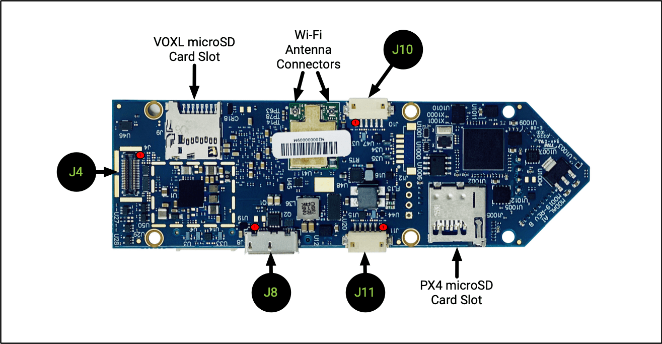
VOXL Flight Board Bottom
Note: 1000 Series connectors accessible from the STM32/PX4
| Connector | Summary |
|---|---|
| J4 | Tracking/Optic Flow Image Sensor (CSI2) |
| J8 | USB 3.0 OTG (ADB) |
| J10 | BLSP7 UART and I2C off-board |
| J11 | BLSP12 UART and I2C off-board |
| VOXL microSD | |
| PX4 microSD | 32Gb Max |
| Wi-Fi Antennas | Included in Kit Molex 1461531100 |
J4 - Tracking/Optic Flow Image Sensor (CSI2)
| J4 Board Connector | Image Sensor (Flex) Mating Connector |
|---|---|
| Panasonic, MPN: AXT336124 | Panasonic MPN: AXT436124 |
Pin-out:
| Pin # | Signal Name | Pin # | Signal Name |
|---|---|---|---|
| 1 | GND | 2 | GND |
| 3 | VREG_L29A_2P8 (AFVDD) | 4 | CAM2_STANDBY_N |
| 5 | CCI_I2C_SDA0 | 6 | VREG_LVS1A_1P8 (DOVDD) |
| 7 | CCI_I2C_SCL0 | 8 | VREG_L3A_1P1 (DVDD) |
| 9 | CAM2_RST0_N | 10 | CAM_MCLK2_BUFF |
| 11 | GND | 12 | GND |
| 13 | MIPI_CSI2_CLK_CONN_P | 14 | CAM_FLASH |
| 15 | MIPI_CSI2_CLK_CONN_M | 16 | CAM_SYNC_0 |
| 17 | MIPI_CSI2_LANE0_CONN_P | 18 | CAM2_MCLK3 |
| 19 | MIPI_CSI2_LANE0_CONN_M | 20 | VREG_L23A_2P8 (AVDD) |
| 21 | GND | 22 | GND |
| 23 | MIPI_CSI2_LANE1_CONN_P | 24 | CAM_RST1_N |
| 25 | MIPI_CSI2_LANE1_CONN_M | 26 | CAM_SYNC_1 |
| 27 | MIPI_CSI2_LANE2_CONN_P | 28 | CCI_I2C_SDA1 |
| 29 | MIPI_CSI2_LANE2_CONN_M | 30 | CCI_I2C_SCL1 |
| 31 | GND | 32 | GND |
| 33 | MIPI_CSI2_LANE3_CONN_P | 34 | VPH_PWR |
| 35 | MIPI_CSI2_LANE3_CONN_M | 36 | GND |
Supported Image Sensors
The following sensors are supported on J4 (CSI2):
- OV7251
Supported modules:
| Description | MPN | Link | Datasheet |
|---|---|---|---|
| Sunny MD102A w/ MSU-M0008-1-01 Adapter | MSU-M0072-1-01 | Buy | |
| ModalAI 166-degree OV7251 B&W VGA Global Shutter | MSU-M0014-1-01 | Buy |
J8 - USB 3.0 OTG
Pin Configuration
| Pin # | Signal Name |
|---|---|
| 1 | VBUS |
| 2 | D- |
| 3 | D+ |
| 4 | ID |
| 5 | GND |
| 6 | MICA_SSTX- |
| 7 | MICA_SSTX+ |
| 8 | GND_DRAIN |
| 9 | MICA_SSRX- |
| 10 | MICA_SSRX+ |
Connector
- KYCON, MPN: KMMX- AB10- SMT1SB30
Mating Connector
- Micro A/B Plug
Notes
- Host mode (e.g. connect a supported USB 3.0 device) requires Micro-A Plug to STD-A in order to get 3.0 SS Functionality. Example cable: Amphenol RUB30-0075 (contact ModalAI for details, available as MCBL-00019-1)
- Host mode USB 2.0 - example cable
J10 - UART or I2C off-board (external Sonar or IMU sensor)
Pin Configuration
| Pin # | Signal Name | Alt Function |
|---|---|---|
| 1 | VREG_3P3V | |
| 2 | SONAR_UART_TX_3P3 | GPIO 53 |
| 3 | SONAR_UART_RX_3P3 | GPIO 54 |
| 4 | EXT_IMU_I2C_SDA_3P3 | GPIO 55 |
| 5 | GND | |
| 6 | EXT_IMU_I2C_SCL_3P3 | GPIO 56 |
Connector
- HIROSE Electric, MPN: DF13-6P-1.25H(50)
Mating Connector
- DF13-6S-1.25C cable assemblies
Notes
- UART and I2C are at 3.3V CMOS levels.
- Connect TX to target device’s RX, and vice-versa.
- I2C has 10K pull-ups.
J11 - BLSP12 off-board (SPEKTRUM)
Pin Configuration
| Pin # | Signal Name | Alt Function |
|---|---|---|
| 1 | VREG_3P3V_SPEKTRUM | |
| 2 | BLSP12_UART_TX_3P3 | GPIO 85 |
| 3 | BLSP12_UART_RX_3P3 | GPIO 86 |
| 4 | BLSP12_I2C_SDA_3P3 | GPIO 87 |
| 5 | GND | |
| 6 | BLSP12_I2C_SCL_3P3 | GPIO 88 |
Connector
- Hirose Electric, MPN: DF13-6P-1.25H(50)
Mating Connector
- DF13-6S-1.25C cable assemblies
Notes
- UART and I2C are at 3.3V CMOS levels.
- Connect TX to target device’s RX, and vice-versa.
- I2C has 10K pull-ups.
Wi-Fi Antenna Connectors (2)
Function
- External Wi-Fi antenna connections
Pin Configuration
- Center Conductor
Connector
- IPEX, MPN: 20449-001E (MHF-4)
Mating Connector
Supported Antennas
Notes
- ANT #1 is for WLAN/BT
- ANT #2 is for WLAN only