LTE Modem and USB Add-on v2 Datasheet
Table of contents
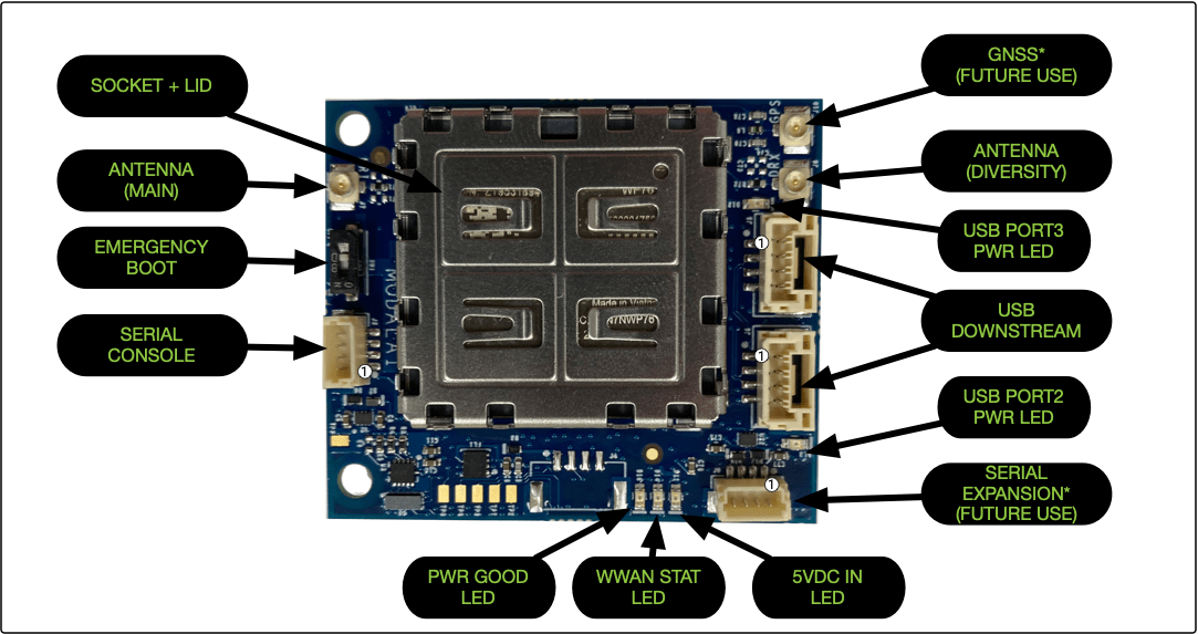
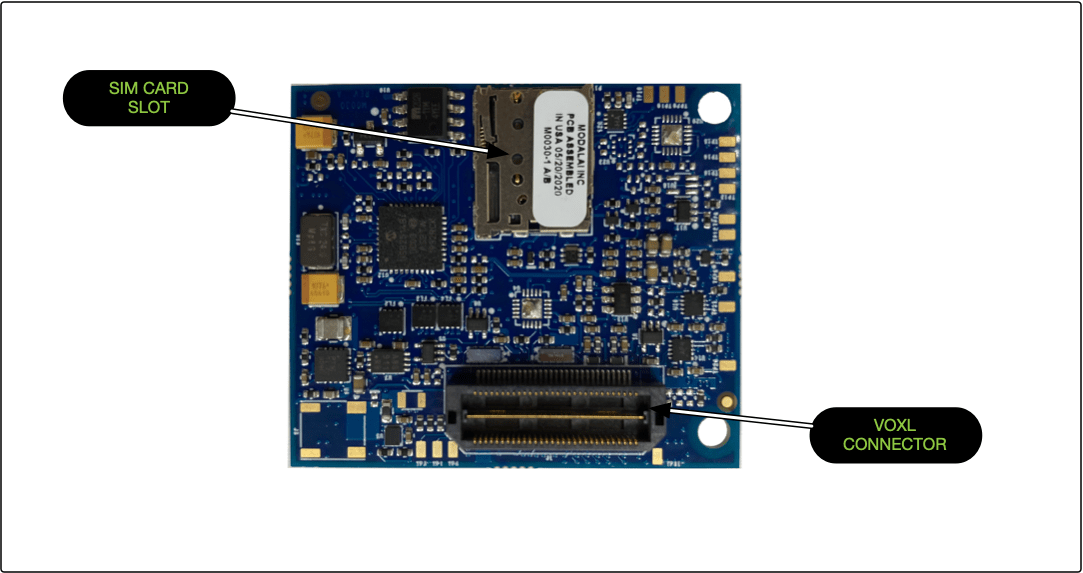
- Board Connections and I/O
- Specifications
- LEDs
- Connector Pinouts
- Environmental
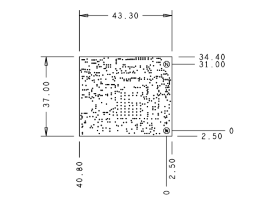
- 2D/3D Drawings
- Emergency Boot Switch
Board Connections and I/O
Specifications
Physical Specification
| Specicifcation | Value |
|---|---|
| Weight (with modem and lid) | 14g |
| Dimensions | 37.0 x 43.3mm |
| Downstream USB ports | 2 |
| Cellular 3GPP Bands Supported | See Radio Specifications below |
| WWAN Antenna Connectors (MIMO) | UFL-R-SMT-110 |
| Recommend Antennas | W3907B0100 |
| Downstream USB Connectors | 4 Position JST GH, Vertical, BM04B-GHS-TBT |
| Downstream USB Mating Connector | JST GHR-04V-S |
| Debug Console Connector | BM04B-SRSS-TB |
| Debug Console Mating Connector | SHR-04V-S-B |
| J1 Connector (bottom of board) | Samtec Inc, MPN: QTH-030-01-F-D-K |
| J1 Mating Connector | Samtec Inc., MPN: QSH-030-01-L-D-A-K |
Radio Options Specification
MDK-M0030-1-00 (No Modem - Carrier Board Only)
MDK-M0030-1-01 (North America - WP7610)
| Specification | Details |
|---|---|
| 4G LTE, Cat-4 | B2, B4, B5, B12, B13, B14, B17, B66 |
| 3G Fallback, HSPA+, UMTS | B2, B4, B5 |
| Bandwidth | up to 150/50 Mbps Download/Upload |
MDK-M0030-1-02 (EMEA - WP7607)
| Specification | Details |
|---|---|
| 4G LTE, Cat-4 | B1, B3, B7, B8, B20, B28 |
| 3G Fallback, HSPA+, UMTS | B1, B8 |
| 2G Fallback, EDGE, GSM, GPRS | 900, 1800 |
| Bandwidth | up to 150/50 Mbps Download/Upload |
MDK-M0030-1-03 (North America - RC7611)
| Specification | Details |
|---|---|
| 4G LTE, Cat-4 | B2, B4, B5, B12, B13, B14, B25, B26, B66, B71 |
| 3G Fallback, HSPA+, UMTS | None |
| Bandwidth | up to 150/50 Mbps Download/Upload |
MDK-M0030-1-04 (EMEA - RC7620)
| Specification | Details |
|---|---|
| 4G LTE, Cat-4 | B1, B3, B7, B8, B20, B28 |
| 3G Fallback, HSPA+, UMTS | B1, B8 |
| Bandwidth | up to 150/50 Mbps Download/Upload |
SIM Cards and Supported Networks
The modem card requires the use of a Nano SIM card.
AT&T (FirstNet), Verizon and Sierra Wireless are supported by MDK-M0030-1-03.
Power Consumption
| Configuration | 5V Power Consumption (mA) |
|---|---|
| Baseline (USB Hub, Glue Logic, All LEDs ON) | 150 |
| Baseline plus Qty-2 USB Peripherals at Max 500mA* | 1180 |
| Baseline + Qty-2 DS USB* + WP Series^ HSDPA Band 1 | 2010 |
| Baseline + Qty-2 DS USB* + WP Series^ HSDPA Band 8 | 1930 |
| Baseline + Qty-2 DS USB* + WP Series^ LTE Band 1 | 2240 |
| Baseline + Qty-2 DS USB* + WP Series^ LTE Band 7 | 2150 |
| Baseline + Qty-2 DS USB* + WP Series^ LTE Band 25 | 2265 |
*For each of the two downstream peripherals removed from the hub, subtract 500mA plus ~30mA logic from the power requirement.
^ Band power consumption information is limited to WP7502, WP7504, and WP8548 (max of these three, at listed mode & band). For other module power consumptions or alternate bands, please contact your local Sierra Wireless FAE, or ModalAI.
LEDs
Status LEDs
| LED | Description |
|---|---|
5VDC IN | Illuminates GREEN when the board is powered |
WWAN STAT | Illuminates GREEN when the modem is initialized |
PWR GOOD | Illuminates solid GREEN when all local power is good |
USB LEDs
The USB PORT2 PWR and USB PORT3 PWR LEDs illuminate green to indicate the USB device is powered when plugged in
Connector Pinouts
J2 - Serial Debug Port
- Connector - BM04B-SRSS-TB
- Mating Connector - SHR-04V-S-B
| Pin | Description |
|---|---|
| 1 | 3.3 VDC |
| 2 | UART_RX_3P3V |
| 3 | UART_TX_3P3V |
| 4 | GND |
J5 - USB Port 2
- Connector - 4 Position JST GH, Vertical, BM04B-GHS-TBT
- Mating Connector - JST GHR-04V-S
| Pin | Description |
|---|---|
| 1 | 5VDC (500mA max) |
| 2 | D- |
| 3 | D+ |
| 3 | GND |
J6 - USB Port 3
- Connector - 4 Position JST GH, Vertical, BM04B-GHS-TBT
- Mating Connector - JST GHR-04V-S
| Pin | Description |
|---|---|
| 1 | 5VDC (500mA max) |
| 2 | D- |
| 3 | D+ |
| 3 | GND |
Environmental
Operating Temperature
TODO
2D/3D Drawings
M0030_REVA_WP_Socket_with_lid.stp
Emergency Boot Switch
Typically left in the OFF state, this switch can be used to enable emergency boot mode.