EMI Mitigation for GNSS Applications
This page focuses on the analysis of EMI sources which can affect GNSS performance on ModalAi Starling 2 and Starling 2 Max UAVs. We provide a list of components, means of testing, results and solutions. Please note that in some cases, the solution is to remove the particular component due to the severity of the interference.
The combined interference of all the components with GNSS signal is quite substantial, in many cases rendering GNSS unusable on these vehicles. For this reason, Starling 2 and Starling 2 Max are no longer advertised as equipped with GNSS receivers, although the products may still ship with GNSS receivers.
Nevertheless, the analysis provides guidance how to work towards achieving much improved GNSS performance. In some cases, simply disabling components that are not needed or upgrading mechanical mount is sufficient to make quick progress.
Additional discussion of the topic can be found on our Forum
Table of contents
- Background
- EMI Sources
- Modifications and Upgrades
- Recomendations for Starling 2
- Recomendations for Starling 2 Max
- Testing Notes and Tips
- How to view live satellite signal strength (SNR)
- Disable power (VBUS) to the USB port used by the wifi dongle on Starling 2 / Max
- Power Down 5G modem (when using M0130)
- GNSS PX4 debug tools (command line)
- How to test a GNSS receiver without VOXL2
- Stress Testing Wifi
- How to Query Available CPU Core Frequencies
- CPU Stress Test Script with Frequency Lock
- IMX412 PLL Frequency Tests
Background
Summary of Main EMI Sources
| Component | EMI Severity | Solution | Notes |
|---|---|---|---|
| TOF Sensor | High | Disable for outdoor use | TOF is for indoor use |
| Hires Camera (IMX412) | High | PLL settings update | TODO |
| Lepton Camera | High | Disable, unplug | (or move away from GNSS) |
| RC Transmitter | High | Move at least 2-3 meters from vehicle | – |
| Wifi Adapter | Medium | Move away from GNSS antenna | Especially on Starling 2 |
| RC Receiver | Low | Move antenna away from GNSS antenna | 1-2 dB drop w/ telemetry enabled |
| CPU Frequency | Low | Avoid 1574.4Mhz | TBD, force perf mode, modify governor |
| M0173 Camera Front End | Low | None | Some concern with 25Mhz clock |
| Tracking Camera (AR0144) | None | None | – |
| LTE Add-on (M0130) | None | Note | May need more testing |
| ESC (M0129) | None | None | – |
TOP Suggestions For Improving GNSS Performance
- Disable TOF sensor (in
voxl-camera-server.conf) - Elevate the GNSS receiver, if possible
- Upgrade GNSS receiver with larger antenna + larger ground plane
- Move any other antennas away from the GNSS antenna (including wifi module)
- Do not use RC Transmitter in close proximity to the GNSS receiver
- (Temporarily) disable some or all cameras for testing
Information About Satellite Signal Strength
- GNSS Receivers are very sensitive to interference, especially around L1 frequency band (1575Mhz)
- Minimum usable SNR is 25-30dB, maximum SNR is around 50dB
- Maximum observable SNR of any satellite depends on its elevation (higher SNR when satellite is right above)
- At least 30dB is required to download the full Ephemeris from each satellite
- At least 4 satellites (30+dB) are required for an initial 3D lock
- Weather conditions (cloud cover, etc) will affect satellite SNR
- In good conditions (no significant interference), a GNSS receiver should get a 3D lock in 30 seconds or less (from cold start)
- Many GNSS receivers are equipped with a small back-up battery, which helps the receiver store the recent GNSS satellite info
- Warm start after a recent lock may only take a few seconds
- Therefore, initial lock time should not be used as a metric of signal quality during repeated tests within a short period of time, unless a cold start has been explicitly commanded
- It is common to observe 2-4 satellites around or above 45dB (per constellation) when the GNSS receiver operates properly
- note that this is highly dependent on the satellite locations, but if the maximum SNR observed is 40 (or even 35), that is a sign of a (big) issue
GNSS Receiver Used For Testing
- Ublox Max M10S (standard in Starling 2 and Starling 2 Max)
Notes on Testing
- Satellite locations are constantly changing (GNSS satellites are not geo-stationary), therefore one cannot directly compare SNR levels from different tests, unless the tests are performed concurrently
- using an additional GNSS receiver (free of any interference) is good practice. Use a similar receiver as device under test or another (official EVK from Ublox, etc)
- Effect of EMI on SNR is not additive. For example, if there are two sources that individually cause a 10dB drop in SNR, it does not mean that having both EMI sources present will result in 20dB SNR drop
Applicable Vehicles
- ModalAI Starling 2
- ModalAI Starling 2 Max
EMI Sources
TOF Sensor
- Note that TOF sensor starts streaming data as soon as camera server starts, even if there are no stream clients
- the data is discarded if there are no camera stream clients
- Significant source of EMI (5-20dB). Do not use with GPS
- the SNR drop is correlated with the sensor FPS and the maximum IR emitter time (which is set using
exposure_max_usinvoxl-camera-server.conf) Testing done by enabling the TOF sensor in camera server config, startingvoxl-camera-serverand optionally runningvoxl-inspect-tof
- the SNR drop is correlated with the sensor FPS and the maximum IR emitter time (which is set using
Solution: Disable the TOF sensor in voxl-camera-server.conf by setting "enabled" property to false
Lepton Sensor connected to M0173
- With Lepton in streaming mode, signal drops 5-10dB when Lepton is right next to GPS receiver, less if farther away
- only when voxl-lepton-server is running
- i2c communication with lepton has no effect
- Changing SPI bit rate has some effect, but Lepton has limitations on SPI bit rate
- Further investigation: figure out if SPI or Lepton itself is emitting the EMI
Solution: do not run voxl-lepton-server or disconnect the Lepton sensor
Hires Cameras (IMX412)
- There are up to two IMX412 cameras on Starling2 Max (front and rear)
- Strong interference observed (10-20dB, especially from rear hires camera)
- camera server must be running and camera stream active (not idle)
- interference depends on the camera PLL settings, image resolution and FPS
- larger interference observed with fpv_misp and eis drivers for IMX412 due to higher clock rates than original driver
- original driver can be found on voxl2 in
/usr/share/modalai/chi-cdk/imx412/
- interference depends on exposure and gain (likely affects the noise due to type of data being sent from camera)
- Running
voxl-camera-serverwithout any stream clients does not start the cameras and does not cause any interference - ** Ongoing investigation to evaluate different camera PLL settings and camera shielding **
Solution: TBD change PLL setting of the camera shield the cameras
RC Transmitter
- RC transmitter (Commando 8) in proximity of GPS receiver
- Even though the Transmitter frequency is in the 900Mhz band, it interferes with GPS L1
Solution: Transmitter needs to be at least 2-3 meters to avoid interference
USB Wifi Dongle
- Starling 2 has the wifi dongle sitting right under the GNSS receiver / antenna
- interference observed when the wifi adapter is active
- moving wifi dongle serveral inches away from the GNSS receiver resolves the issue
- Starling 2 Max should not be affected because the Wifi dongle is already mounted at the bottom
- Loading up the WIFI link increases the interference, see test example using
iperf - The EMI could be coming from the antenna or the PCB, in case of a small wifi adapter, it is impossible to tell
Solution: disable wifi dongle or move it as far away from GNSS receiver / antenna as possible
RC Receiver
- When telemetry is enabled, initial tests show 1-2 dB drop
Solution: If possible, move the RC Rx antennas farther from the GNSS receiver / antenna
CPU clock frequency
- CPU cores 4-6 have available frequency of 1574.40Mhz, which is very close to GPS L1 frequency of 1575.42Mhz
- Test: fix cpu frequency to 1574.4Mhz, load the cpu cores and observe the satellite SNR in
voxl-portal - See below for a test script to stress test cores at a certain frequency
- It appears that setting cores 4-6 to frequency 1574400 and running a stress test, the SNR drops by 2-5 db. Frequencies one notch up or down from 1574400 do not cause any interference ( 1478400 and 1670400)
- Placing GNSS module right next to QRB5165 SIP does produce noticeable interference, however if the GNSS module is in the back (the original location on Starling 2 Max), observing 2-5 dB drop during CPU stress test with cores 4-6 set to 1.5744Ghz.
- This most likely implies that the EMI is coming from PMIC (located in the back of VOXL2) or the power wiring
- Note that hitting that exact frequency is not likely, however it would be nice to guarantee avoiding this frequency
Solution:
- Set cpu mode to perf mode will force all cores to the max frequency
- Set minimum (or maximum) frequency for cores 4-6 above (or below) 1574400
- Blacklist 1.5744 Ghz - how?
M0173 Camera Front End
- X1 25Mhz xtal and U7 high speed buffer
- are needed for providing a 25Mhz clock for Lepton camera
- 25Mhz clock is provided to Lepton via the 8-pin connector
- There is some EMI at 1575Mhz, observed using an RF spektrum analyzer
- it seems there is no effect at all on SNR, GNSS receiver is filtering it out
- fixed frequency uniform interference is easier to deal with
- Tested by wiring a on/off switch to the whole Lepton power (including clock)
- lepton power and clock can be cycled on / off while observing satellite SNR
Solution: not needed. unplug the 8-pin Lepton cable from M0173 just in case
- Removal of R13 on M0173 completely disables the Lepton functionality, including the 25Mhz clock
- Future variants of this board will be able to control Lepton power and clock via SW
Tracking Cameras (AR0144)
- Test: run voxl-camera-server and stream both tracking camera feeds
- use either
voxl-portalto view the images orvoxl-inspect-camto trigger the stream
- use either
- no interference observed
Solution: not needed
LTE Add-on (M0130)
- Based on customer testing, disabling the power to the LTE card via GPIO has not resulted in any improvements
Solution: none required?
ESC (M0129)
- ESC used in Starling 2 and Starling 2 Max is ModalAI M0129
- Tests: observe GNSS SNR using
voxl-portalwhile testing elements involving Modalai ESC - Move an idling ESC (no UART comms, powered externally) next to GNSS antenna (5cm apart, do not block antenna)
- No observed effect on the satellite SNR from the ESC board, excluding active UART
- Using Starling 2 Max, stop and start voxl-esc px4 driver to stop and start UART communication:
px4-qshell voxl_esc stop px4-qshell voxl_esc start- No observed effect on the satellite SNR from UART communications (2mbps)
Solution: none required
Modifications and Upgrades
The following modifications will help improve the GNSS signal quality
Mechanical Modifications
- Move GNSS receiver as far as possible from electronics that emits EMI
- use a 4-6-inch mast in the center (above roll cage) or in the back
- need a longer 6-pin cable or an extension for GNSS receiver
- use a copper ground plane under the GNSS receiver
- optionally, use the upgraded GPS mast from Starling 2 Max V3 (CAD available), no need for longer cable
- CAD available here
- Twisted GPS cable routed to the side of the VOXL2 board generally performs better
- Do not run cables on top of potentially noisy components like CPU, PMIC, etc
- Shield cameras (TBD)
GNSS Receiver Upgrade
- use another GNSS receiver with a larger antenna and / or ground plane
- suggested PCB / Ground plane size : > 35mm
- note that using a custom ground plane right under the antenna may de-tune the antenna
Thermal Considerations
- Unless the GNSS receiver is equipped with a TCXO (Temperature Compensated Crystal Oscillator), rapid changes in the oscillator’s temperature will introduce a temporary frequency bias, which will reduce SNR and solution quality.
- If the vehicle is operating in environments, where temperature can change rapidly, consider enclosing the GNSS receiver to slow down the temperature change, so that the GNSS receiver can track the frequency bias quickly enough.
Recomendations for Starling 2
- Disable the TOF camera in
voxl-camera-server.conf - Unplug the 8-pin Lepton cable from M0173 (just to be sure Lepton sensor is not used)
- move the Wifi adapter from under the GPS receiver
- in order to do this, it may be best to upgrade M0141 to M0151 USB breakout (for more flexibility)
- choose M0151 board + cables (will get a USB3.0 cable), alternatively get MCBL-00009 or MCBL-00041 for USB2.0 (to save weight)
- make sure the gps cable is twisted (not too tight) and is not routed over the VOXL2 board (route along the side)
- route the cable along the side of the GPS mast
- upgrade GNSS receiver to one with larger antenna and larger ground plane, if possible
Recomendations for Starling 2 Max
- Disable the TOF camera in
voxl-camera-server.conf - Unplug the 8-pin Lepton cable from M0173 (just to be sure Lepton sensor is not used)
- Remove wifi dongle if wifi not used, otherwise perform testing to make sure wifi is not interfering with GPS
- if interference detected, move the wifi adapter farther from GNSS antenna
- install a new mast that is shipping with Starling 2 Max V3 (CAD provided)
- making the mast taller should help, but will need a longer power/uart/i2c cable
- make sure the gps cable is twisted (not too tight) and is not routed over the VOXL2 board (route along the side)
- route the cable along the side of the GPS mast
- upgrade GNSS receiver to one with larger antenna and larger ground plane, if possible
- modify the new GPS mast (from Starling 2 Max V3) to fit the new receiver
Testing Notes and Tips
It is recommended to begin testing with as many components disabled as possible with the goal of establishing a baseline of high satellite SNR. After achieving the baseline, start turning on and testing other components that are required for vehicle operation.
How to view live satellite signal strength (SNR)
- Make sure PX4 service (
voxl-px4) is running - use
voxl-portalto open the GPS debug page (Debug -> GPS tab)
Disable power (VBUS) to the USB port used by the wifi dongle on Starling 2 / Max
- pin GPIO_157 controls VBUS, which is USB power on VOXL2
- to disable, run
voxl-gpio write 157 0 - to enable, run
voxl-gpio write 157 1
Power Down 5G modem (when using M0130)
- Full card power OFF (almost as if it is not installed) via GPIO_1
- to disable, run
voxl-gpio write 1 0 - to enable, run
voxl-gpio write 1 1
GNSS PX4 debug tools (command line)
- make sure PX4 is running
- get overall GNSS state and status:
px4-listener sensor_gps - view raw satellite SNR:
px4-listener satellite_info
How to test a GNSS receiver without VOXL2
- use a serial-to-usb adapter to connect GND, 5V, TX and RX and use Ublox Ucenter
Stress Testing Wifi
- install iperf on a linux host and VOXL2:
(sudo) apt install iperf - run on linux host :
iperf -s - run on voxl2 :
iperf -c <host-ip-address> - look for any changes in SNR when transitioning between idle and running the test
How to Query Available CPU Core Frequencies
- List available cpu frequencies on Voxl2 (qrb5165). Units are Khz.
cat /sys/devices/system/cpu/cpu*/cpufreq/scaling_available_frequencies 300000 403200 518400 614400 691200 787200 883200 979200 1075200 1171200 1248000 1344000 1420800 1516800 1612800 1708800 1804800 300000 403200 518400 614400 691200 787200 883200 979200 1075200 1171200 1248000 1344000 1420800 1516800 1612800 1708800 1804800 300000 403200 518400 614400 691200 787200 883200 979200 1075200 1171200 1248000 1344000 1420800 1516800 1612800 1708800 1804800 300000 403200 518400 614400 691200 787200 883200 979200 1075200 1171200 1248000 1344000 1420800 1516800 1612800 1708800 1804800 710400 825600 940800 1056000 1171200 1286400 1382400 1478400 1574400 1670400 1766400 1862400 1958400 2054400 2150400 2246400 2342400 2419200 710400 825600 940800 1056000 1171200 1286400 1382400 1478400 1574400 1670400 1766400 1862400 1958400 2054400 2150400 2246400 2342400 2419200 710400 825600 940800 1056000 1171200 1286400 1382400 1478400 1574400 1670400 1766400 1862400 1958400 2054400 2150400 2246400 2342400 2419200 844800 960000 1075200 1190400 1305600 1401600 1516800 1632000 1747200 1862400 1977600 2073600 2169600 2265600 2361600 2457600 2553600 2649600 2745600 2841600 - Force a core to a specific frequency by setting min and max to the same value:
voxl2:$ echo 1574400 > /sys/devices/system/cpu/cpu4/cpufreq/scaling_max_freq
voxl2:$ echo 1574400 > /sys/devices/system/cpu/cpu4/cpufreq/scaling_min_freq
CPU Stress Test Script with Frequency Lock
- Dependencies:
apt install stress-ng
#!/bin/bash

# Dependencies:
# apt install stress-ng

# List all available frequencies for all cores:
# cat /sys/devices/system/cpu/cpu*/cpufreq/scaling_available_frequencies

# Target CPU cores
CORES=(4 5 6)

# Frequency in kHz
#FREQ=1478400
FREQ=1574400
#FREQ=1670400

# Stress duration (seconds)
DURATION=5

# Stress workers (one per core)
WORKERS=${#CORES[@]}

echo "Setting CPU frequency to $FREQ kHz for cores: ${CORES[*]}"

for CPU in "${CORES[@]}"; do
    echo $FREQ > /sys/devices/system/cpu/cpu$CPU/cpufreq/scaling_min_freq
    echo $FREQ > /sys/devices/system/cpu/cpu$CPU/cpufreq/scaling_max_freq
done

echo "Verifying frequencies..."
for CPU in "${CORES[@]}"; do
    cat /sys/devices/system/cpu/cpu$CPU/cpufreq/scaling_cur_freq
done

echo "Running stress test for $DURATION seconds..."

taskset -c 4-6 stress-ng \
    --cpu $WORKERS \
    --timeout ${DURATION}s \
    --metrics-brief

echo "Stress test complete."
IMX412 PLL Frequency Tests
IMX412 camera has several internal clocks, which are generated from the 24 Mhz base frequency that is fed from Voxl2 to all cameras. These clocks are configured during the camera initialization phase - the settings are contained within the imx412 sensormodule files.
Tests were performed to measure the effect of the PLL / MIPI bitrate on the GNSS Satellite SNR, while keeping all other settings the same (gain, exposure, fps).
The test was set up as follows:
- generate imx412 sensormodule drivers for desired frequency range (e.g. 1200-2100 Mhz / Mbps)
- all tests use the same camera resolution 3840x2160 at 45FPS
- higher fps = more interference
- tried to have a relatively large frequency range while keeping the fps high (low mipi rates cannot support high fps), so 45fps was a good compromise
- repeat for each frequency
- copy appropriate sensormodules (for specific frequency) into /usr/lib/camera/
- log baseline satellite signal strengths for all satellites 10 seconds – this allows the experiment to not depend on any initial SNR captures at the beginning of the test, since SNR can change relatively quickly due to the environmental factors
- start voxl-camera-server and voxl-inspect-cam hires_front_misp_color hires_down_misp_color and wait for 3 seconds
- collect satellite SNRs for 10 seconds while the cameras are streaming
- stop voxl-camera-server
- wait for 3 seconds and repeat the loop for the next frequency
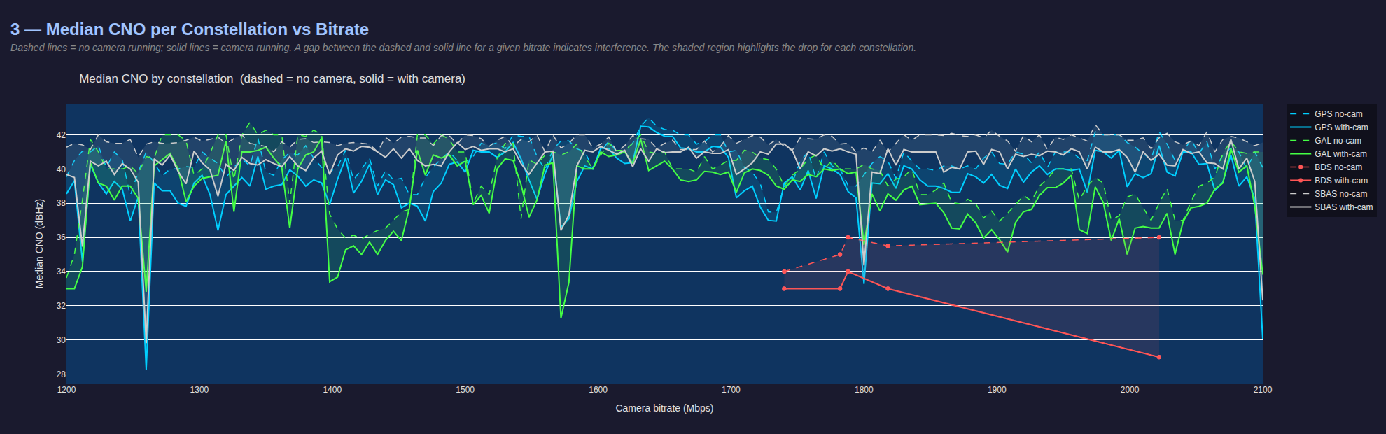
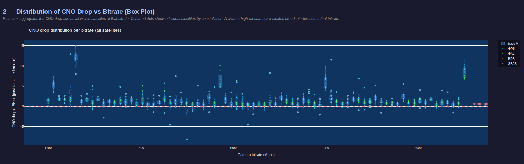
After data has been collected, analyze the logs and generate plots.
The tests were done outdoors using Starling 2 Max with original GPS receiver + V3 GPS mast and 75mm FR4 (with copper) circular plate under the receiver. Full Sun light and exposure was set to 0.1ms, gain to 100 (1.0x). During testing it was discovered that the most interference was present when the image was darker than normal (under-exposed) – probably related to specifics of the MIPI packets that are causing the interference.
Note that the default IMX412 MIPI bitrate was set to the maximum that the camera officially supports, which is 2100Mbps.
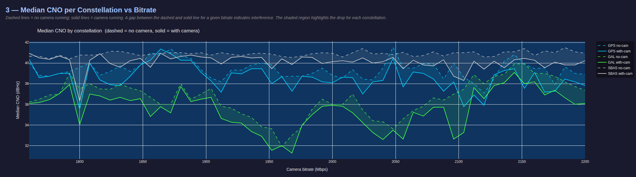
As the plots show, there are several peaks where the satellite SNRs drop by 10-15dB, as initially noted in the overall system testing. Additionally, 2100Mbps is one of the worst frequencies to use, based on this data.
As a result of testing, the following frequencies were identified as causing significant interference with GPS L1 band:
- 1212Mhz
- 1260Mhz
- 1572-1578 Mhz (L1 band!!)
- 1800Mhz
- 2100Mhz
There results below show 3 tests:
- 1200-2100 Mhz sweep with steps of 30Mhz
- 1200-2100 Mhz sweep with steps of 6Mhz
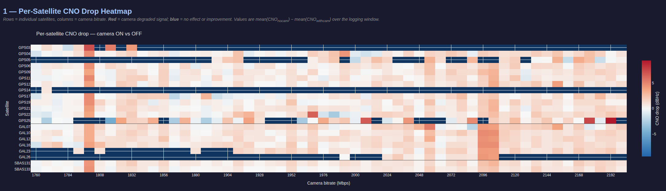
- 1760-2200 Mhz sweep with steps of 8Mhz (focusing on the upper range, slightly different PLL configuration)
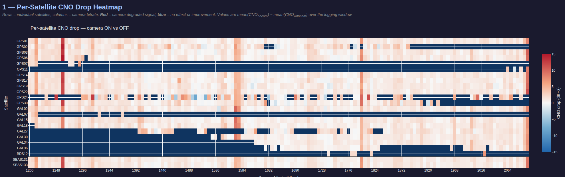
1200-2100 Mhz sweep with steps of 30Mhz
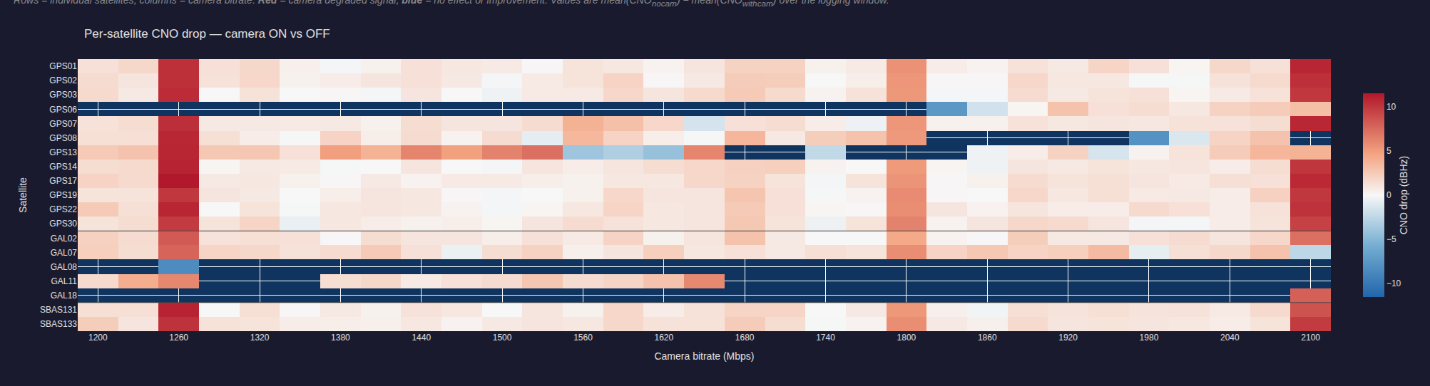
1200-2100 Mhz sweep with steps of 6Mhz
1760-2200 Mhz sweep with steps of 8Mhz