DTC Starling Integration (Community Supported)
Table of contents
Overview
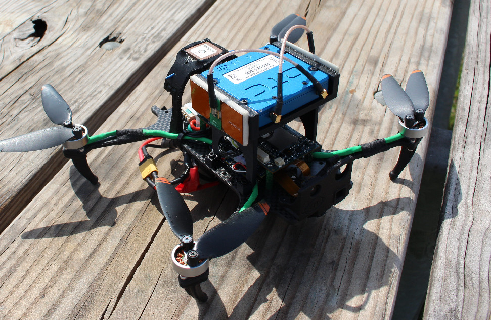
This page will cover how to add and mount a DTC Radio onto the Starling.
Below are some helpful links from DTC:
As this is a community supported modem the ModalAI team cannot provide direct support. Instead please direct questions to US.Technical.Support@domotactical.com or UK.Technical.Support@domotactical.com
For Setting up the DTC Radio with the VOXL2,refer to the DTC User Guide Page located here.
Requirements
Hardware
The following ModalAI hardware is required to establish a DTC network connection between a VOXL-based product and a host device (computer, tablet, etc.).
| Part Number | Description | Link |
|---|---|---|
| MCCA-M0078 | VOXL USB Expansion Board v2 | Purchase |
| MRB-D0005-4-V2-C6-M22 | Starling V2 Drone (with Battery) | Purchase |
3D Drawings
** Below are links to the individual STEP and STL files for download. the links will take you to the Google Drive file location **
Hardware Setup
Please Note: the Li-Ion battery, recommended for the Starling is rated to handle ONLY the Starling. We recommend getting a separate 2 Cell or 3 Cell battery with a higher mAh when using the Starling with the DTC radio for long flights.
Starling Side
- Disconnect the GPS Tower from the Starlings VOXL2.
- To remove the GPS Tower from the Starling, unscrew the four center screws on the bottom of the Starling.
- Next Unfasten the USB Hat from the Starling (Hold the standoffs under the VOXL2 to prevent twisting while unscrewing).
- Remove the USB Hat from the VOXL2 along with the wifi dongle attached.
- Socket the USB Expansion Board V2 onto the VOXL2 J3.
- Fasten the USB Expansion Board V2 down.
- Attach the DTC Mount by lining up the holes on the center mount with the Starling holes. (Image below)
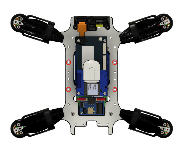
- Lastly, fasten down the DTC Mount with M2 screws and M2 nut. (Optional) You can reattach the GPS Tower by placing it further back and reconnect it to the VOXL2.
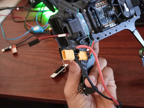
Powering DTC Radio
We will need a method to power both the DTC Radio and the Starling, The simplest way to accomplish this is to send power from the battery to both the Power module and the DTC Radio.
Required Components:
- 2 Pin Female Rectangular Molex Connector
- XT30 Male Connector
- XT30 Female Connector
- Wires
- Wire Cutters
- Wire Stripper
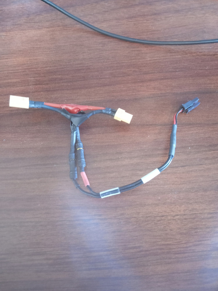
Instructions:
- Solder on the wires to the the XT30 Male connector taking note of the positive and negative wires.
- Split the wire coming from the XT30 Male Connector.
- On the first end of the split wire solder on the XT30 Female Connector.
- On the second end of the split wire solder on the Female Molex Connector.
** Note: Since the DTC Radio requires between 16 and 6V to operate we have to use the power from the battery and not splice off the power going into the VOXL2. Secondly since all the ESC pads are being used for the motors there isn’t an easier method of getting the required voltage other than from the battery. **
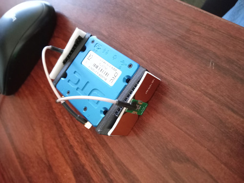
DTC Radio
** Please be sure that the DTC Radio is configured properly as a peripheral before mounting it onto the Starling. **
- Connect the Antennas to the DTC radio.
- Place the DTC Radio in the Mount holder and make sure the holes line up.
- Next Wrap the Antennas over the top of the Radio crossing one another to reach the sides of the DTC mount.
- Point the 3M VHB Pads toward the DTC Radio.
- Attach the Antennas to the sides, either by the VHB pads or using Velcro, or tape.
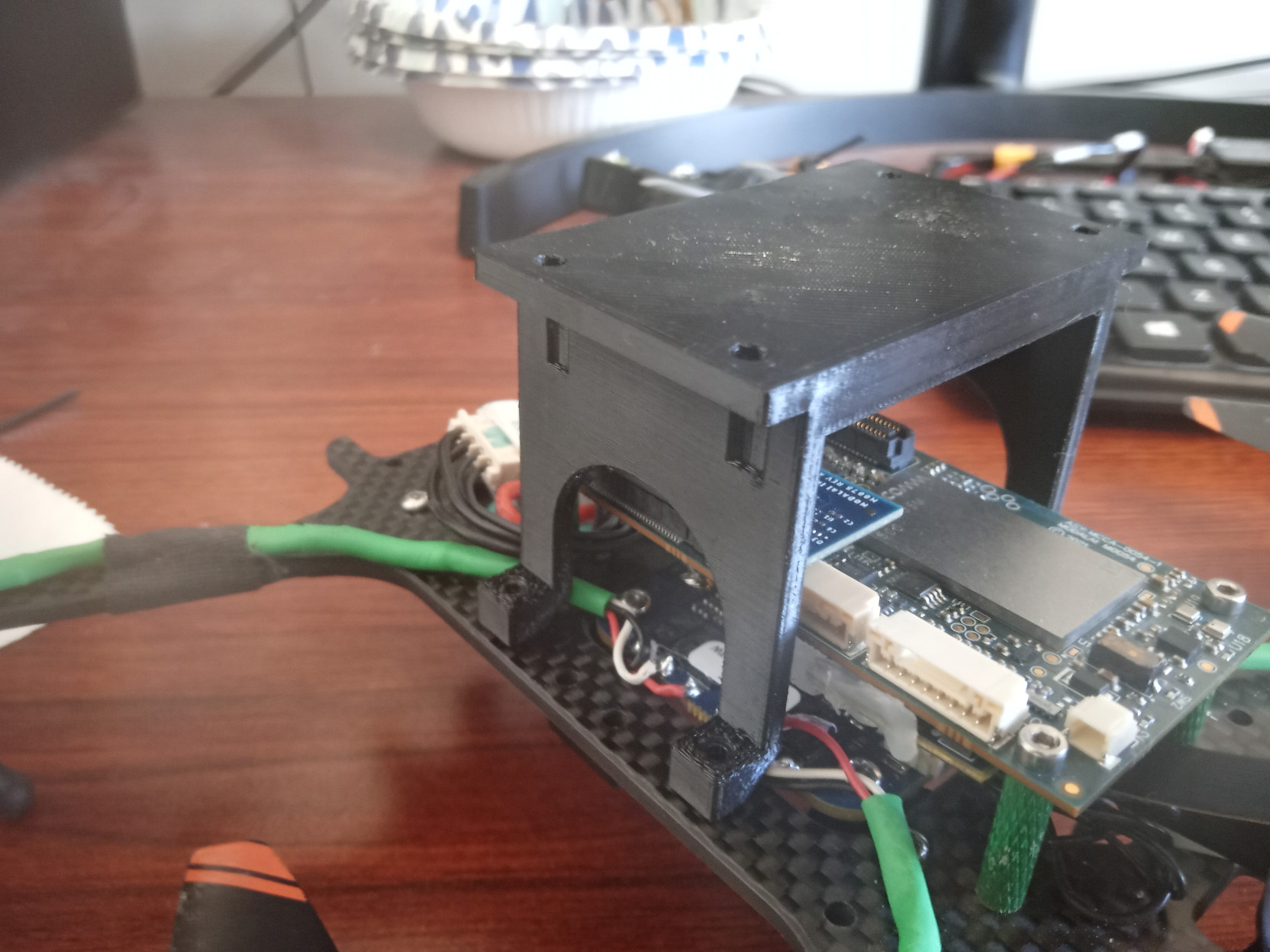
Connecting it All Together
- Connect the DTC Mount to the DTC Mount Holder
- Fasten down using 4 x M2 Screws
- Plug in the Power splitter to the Power Module for the Starling.
- Connect the Power splitter’s Molex end to the Molex connector on the the DTC’s Power cable.
- Connect the 5-pin jst of the communications cable to the USB2 port on the DTC Radio
- Connect the 4-pin jst of the Communications cable to the USB port on the USB2 HAT for the VOXL2
- Lastly, connect the battery to the Power splitter and the VOXL2 and DTC radio will now be Powered
Check the other DTC Radio to ensure that the mesh shows that two nodes are appearing on the network.