Delta Build Guide
The following is a step by step manual as to how to build the delta wing to fly with the ModalAI VOXL 2 and VOXL2-IO breakout board.
Hardware required for the build is the following:
1. SoloGood Delta Wing
2. VOXL 2
3. VOXL 2 IO breakout board
4. Camera Interposer
5. IMX 412 + MIPI
6. Microhard Daughter Board + Microhard + Antennas
7. Fan
8. 3D Printed holster for ModalAI Components
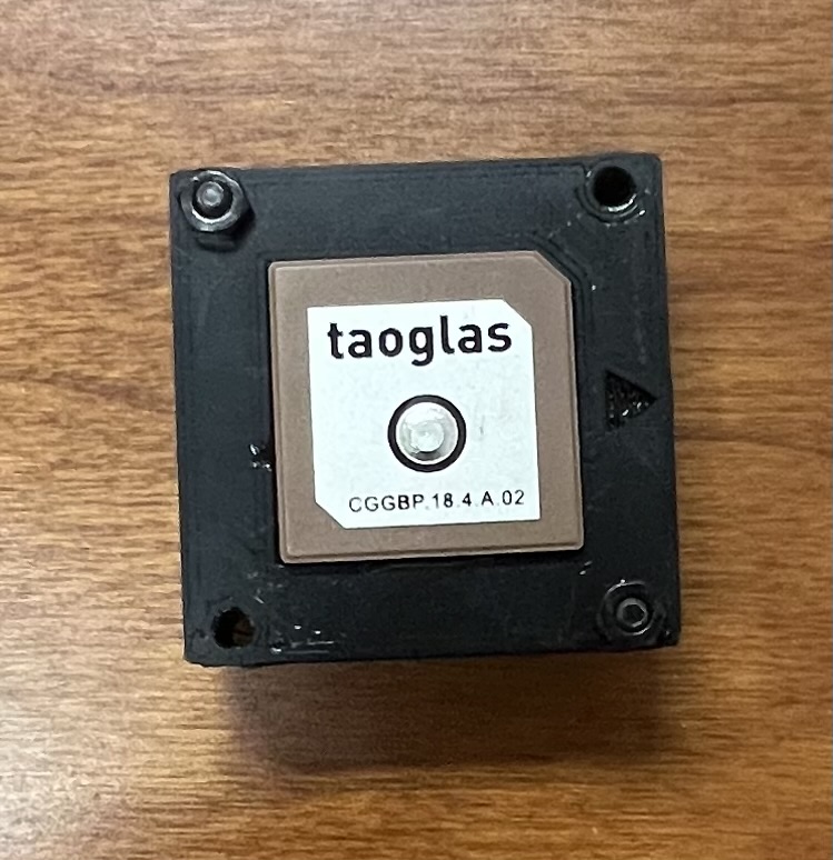
9. M10N GPS
10. Airspeed sensor
11. Distance Sensor (lidar)
12. 35 AMP ESC
13. Motor
14. Propellor
15. Servos
16. iFixIT Tool Kit or something similar
17. Super Glue (Fast Dry)
18. Velcro or two sided tape
19. X-ACTO/Precision Knife
Below is the step by step to initially assemble the delta wing. Be prepared to use a lot of super glue!
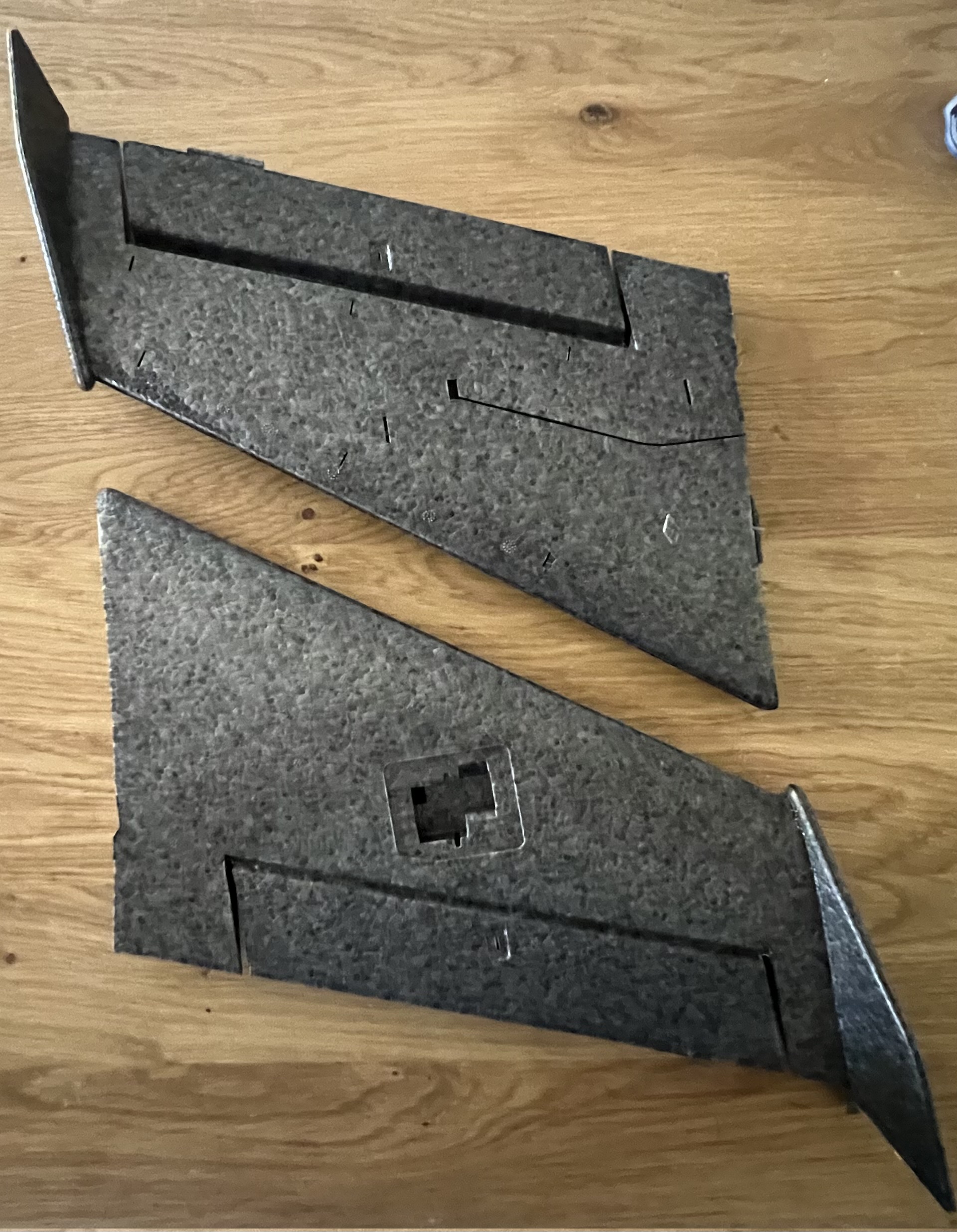
Proceed to remove the wings from the box as well as the winglets that attach to the side of the wings:
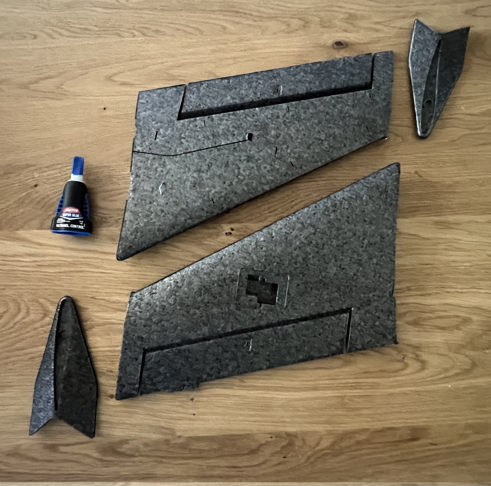
Proceed to lather the ends of the wing with the super glue and attach and press firmly the winglets to adhere to the super glued wing - result should look as follows:
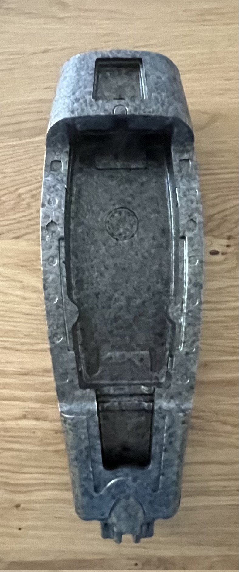
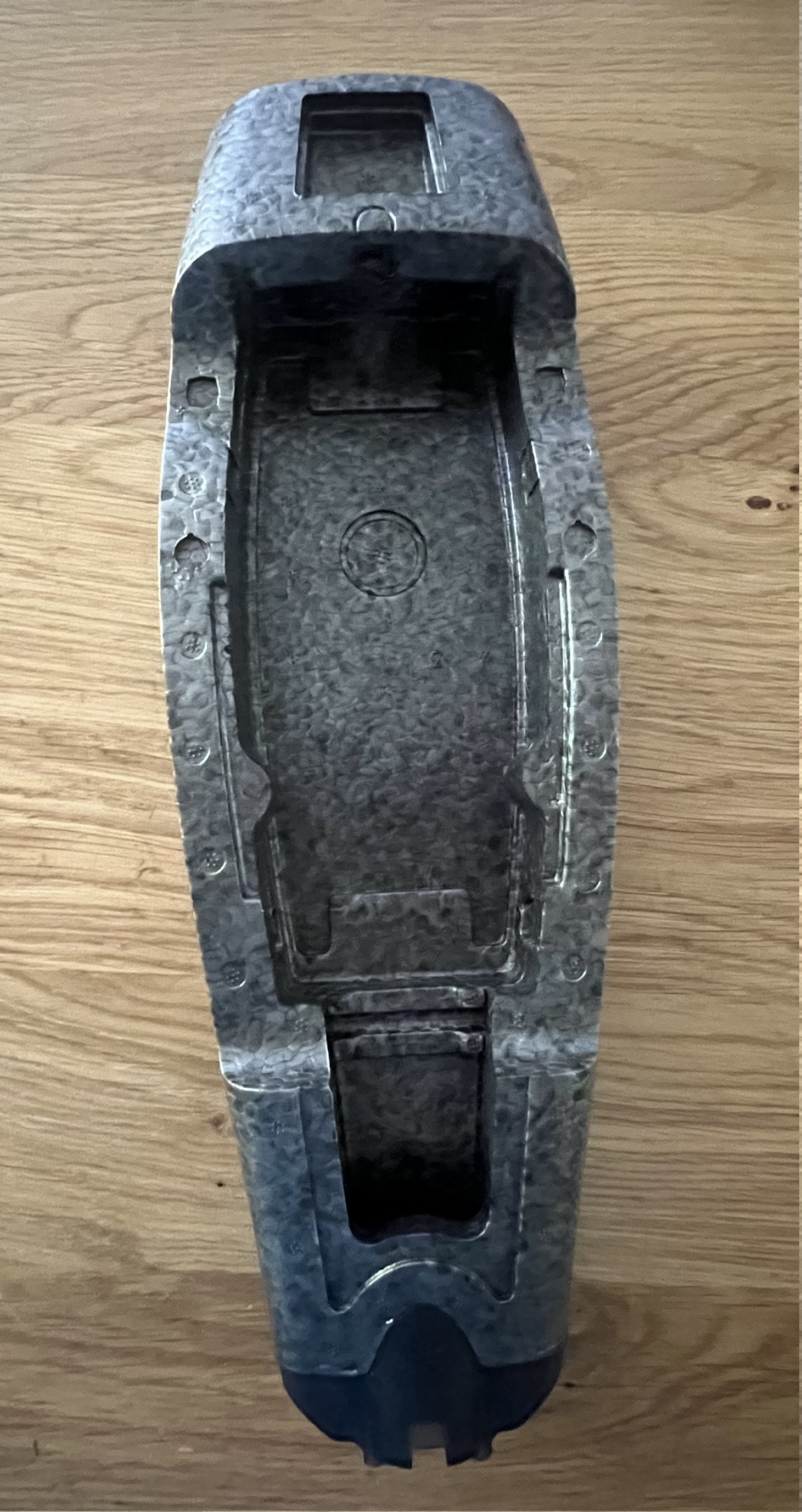
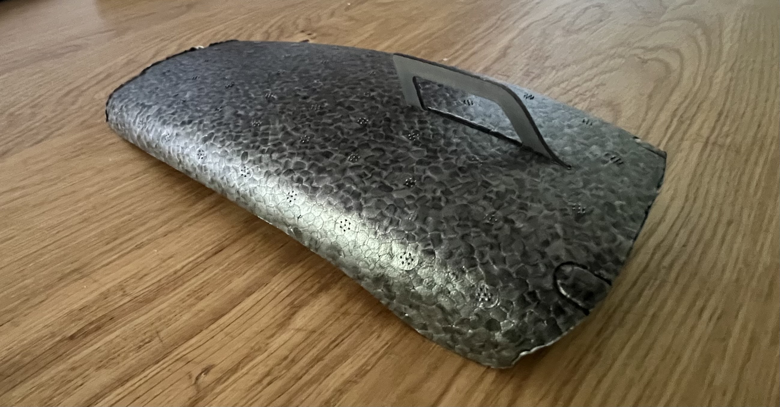
Once the wings have dried, we can move onto the fuselage - proceed to grab the top and bottom pieces of the fuselage:
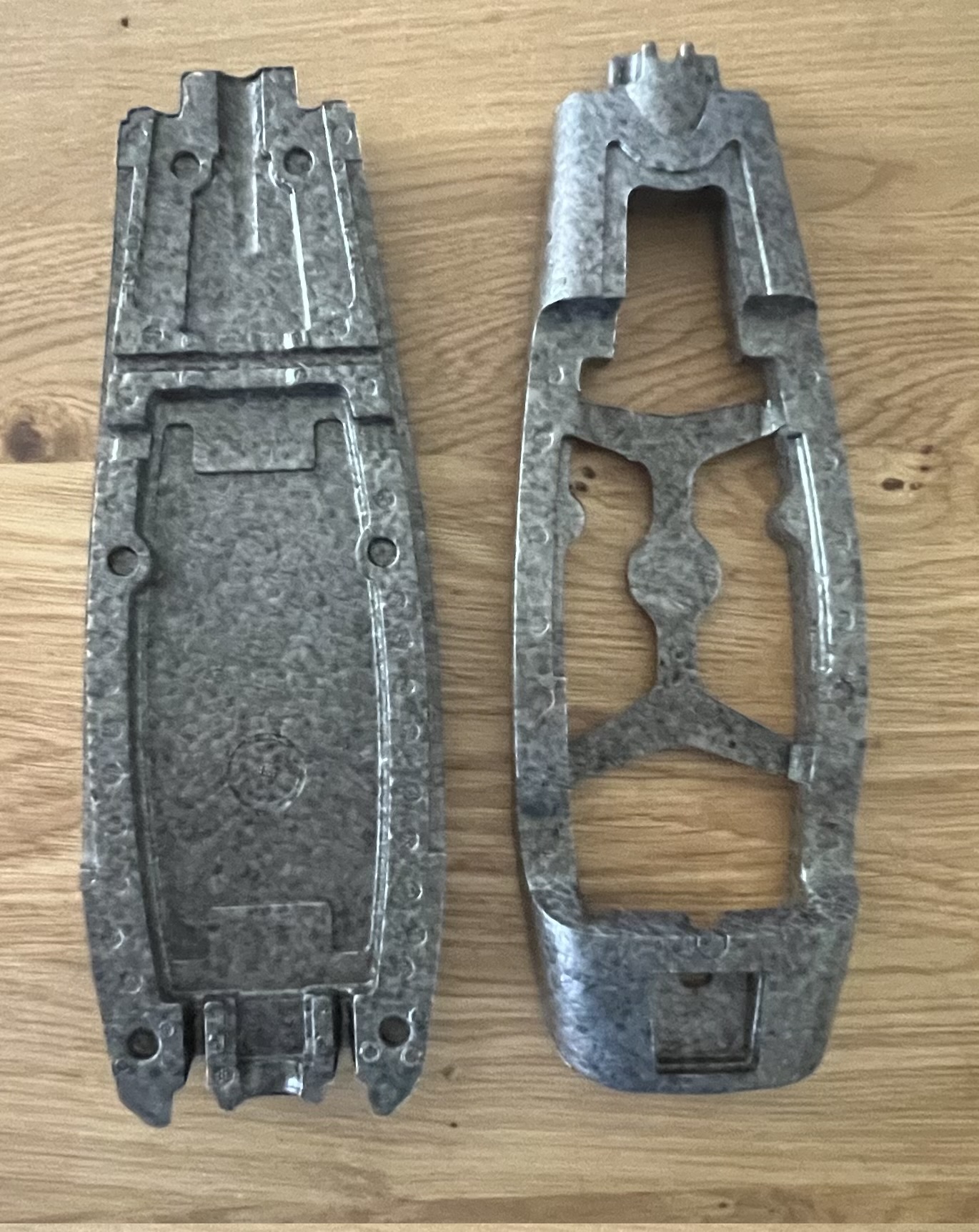
At this point we can remove the support styrafoam from the top piece of the fuselage:
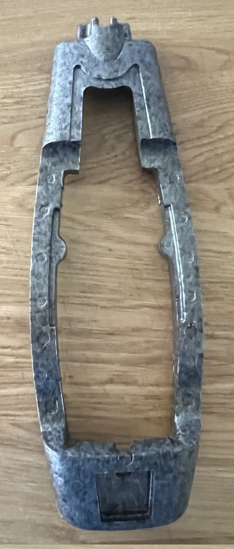
We can not lather the top or bottom of the fuselage with glue and then stick the two pieces together and hold till glue has dried:
Once the fuselage is dried, we can grab the plastic motor mount:
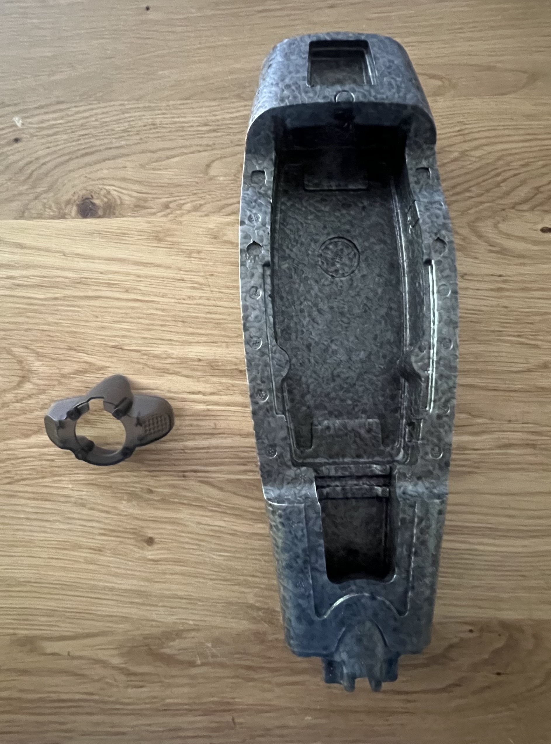
Lather the end of the fuselage with the super glue and proceed to stick the plastic motor mount on the end and hold till dry:
Now we can focus on the top piece that covers the components internally - grab the top hat and the plastic fin:
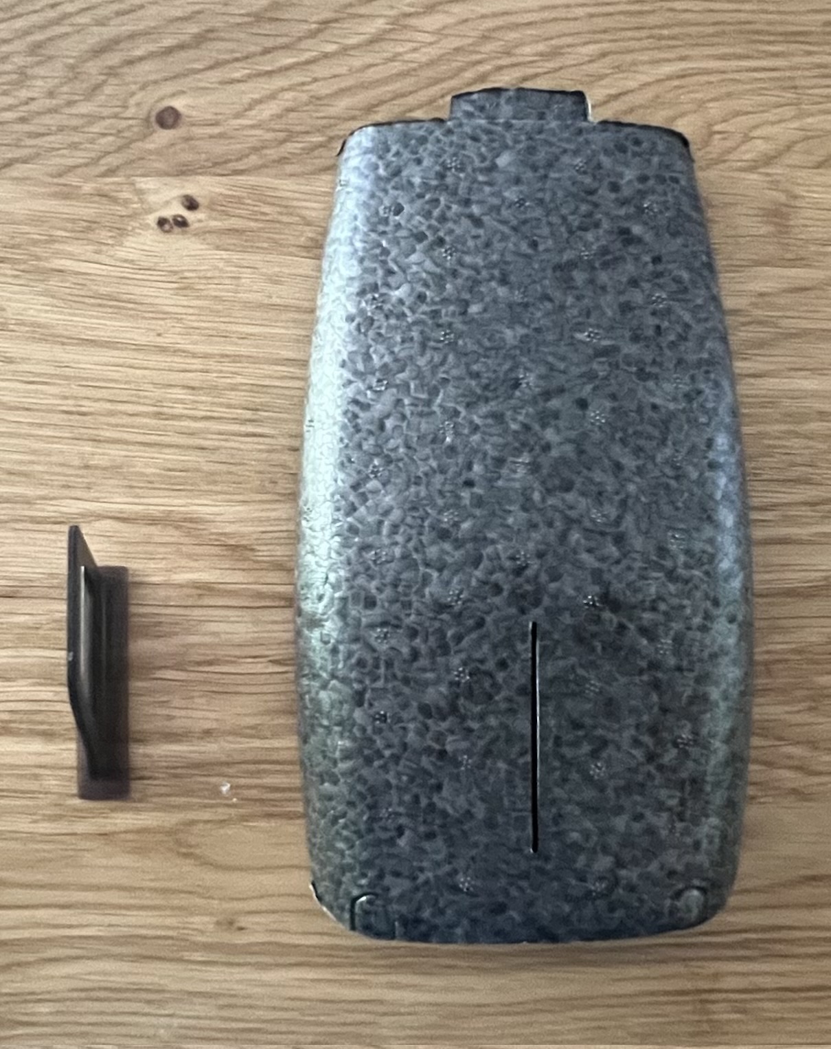
Proceed to place glue on the inside under belly of the top hat and then mount the fin from the bottom - result should look like this:
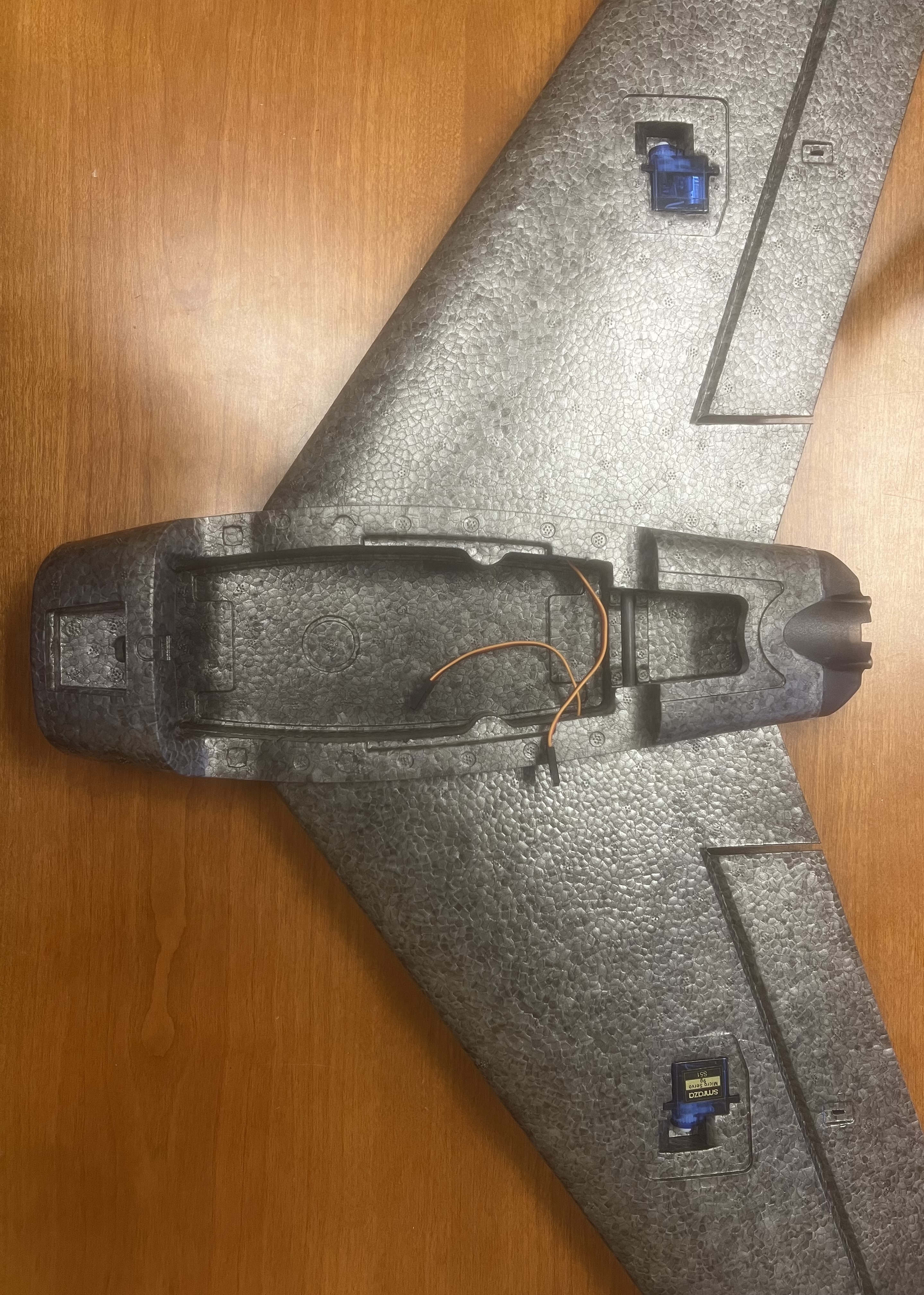
At this point we can start adding the required sensors, servos, motors, etc. to the fixed wing. At this point we will be adding the servos to each of the wings - top and bottom view are below:
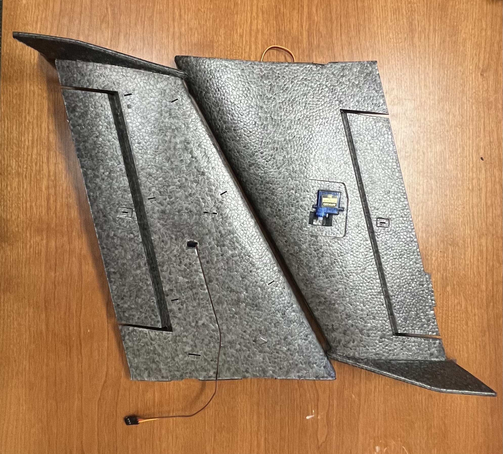
Once the wings have the servos places and the wires on the bottom from the servos have been places into the thin encasing on the belly of the wings, proceed to take the 3-pin endpoint from the servo and place it through the hole on the side of the fuselge - you can do this for both wings.
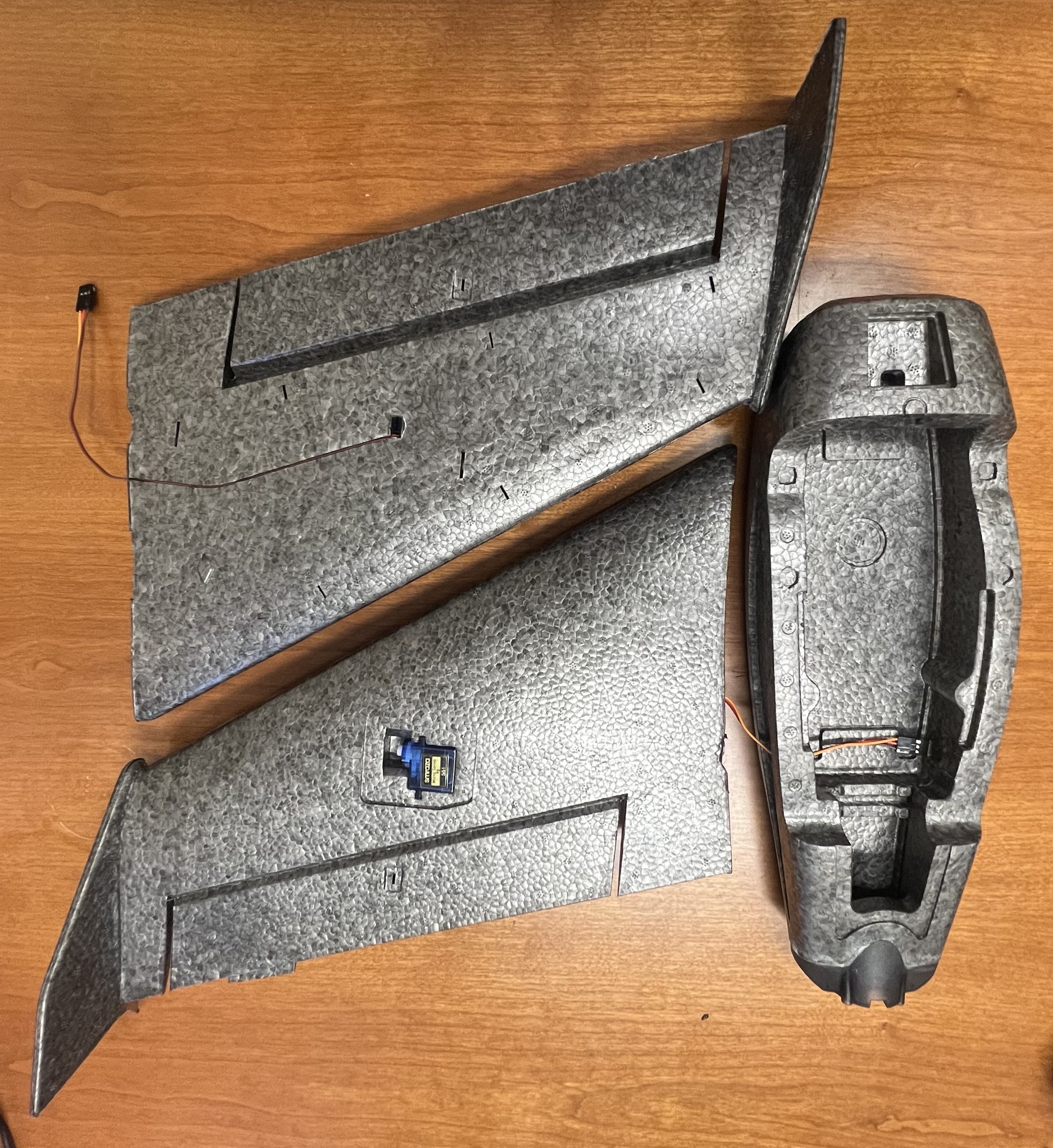
At this point we can place super glue between the wings and the side of the fuselage and force the pieces all together. Hold together for a minute until there is a strong grip between the wings and fuselage.
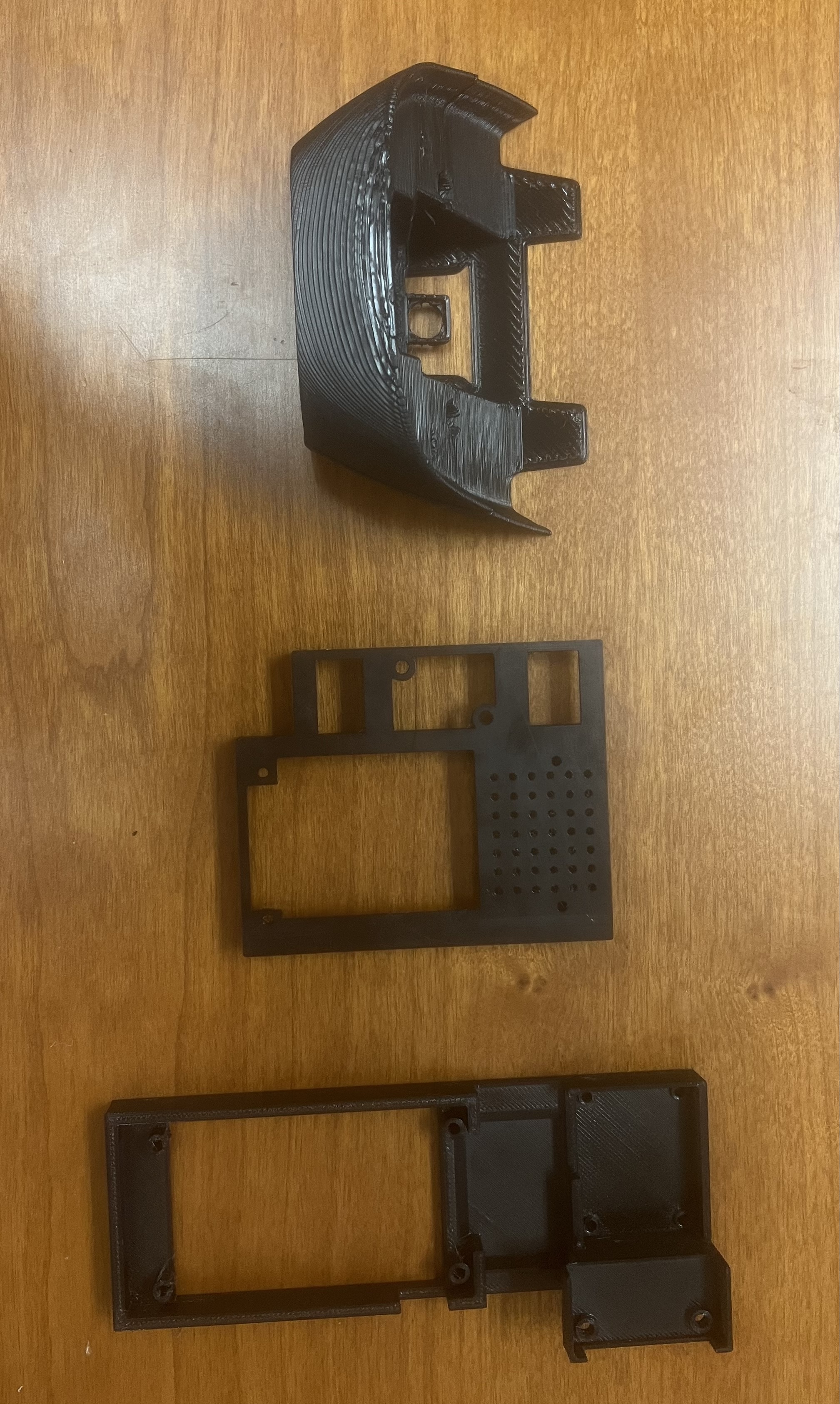
Now place the delta wing down as we will be focusing on the VOXL 2, VOXL 2 IO, Microhard Daughter Board, Cooling Fan, Camera Interposer, PWM Breakout Board, Airspeed Sensor, and GPS. The following steps will require a 3D printer and or the pieces/holsters to be pre printed. In order to find the CAD design of the board, please follow the links here:
- Fixed Wing VOXL 2 Case
- Fixed Wing Nose Case Bottom
- Fixed Wing Nose Case Top
- Fixed Wing VOXL 2 Microhard Case
- Fixed Wing M10N GPS Case Bottom
- Fixed Wing M10N GPS Case Top
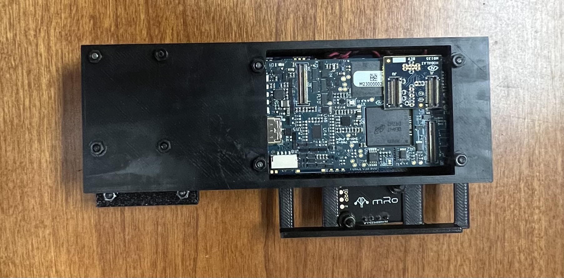
Once all the above have been printed, together it should look like this:
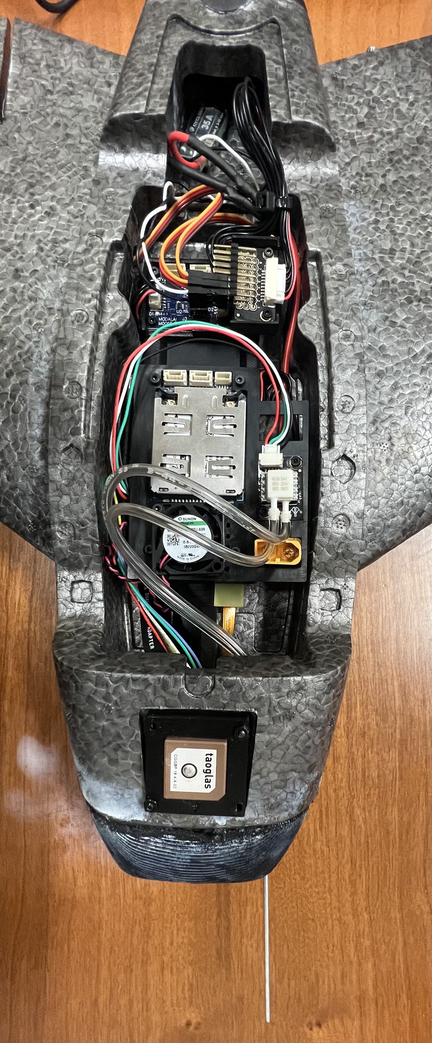
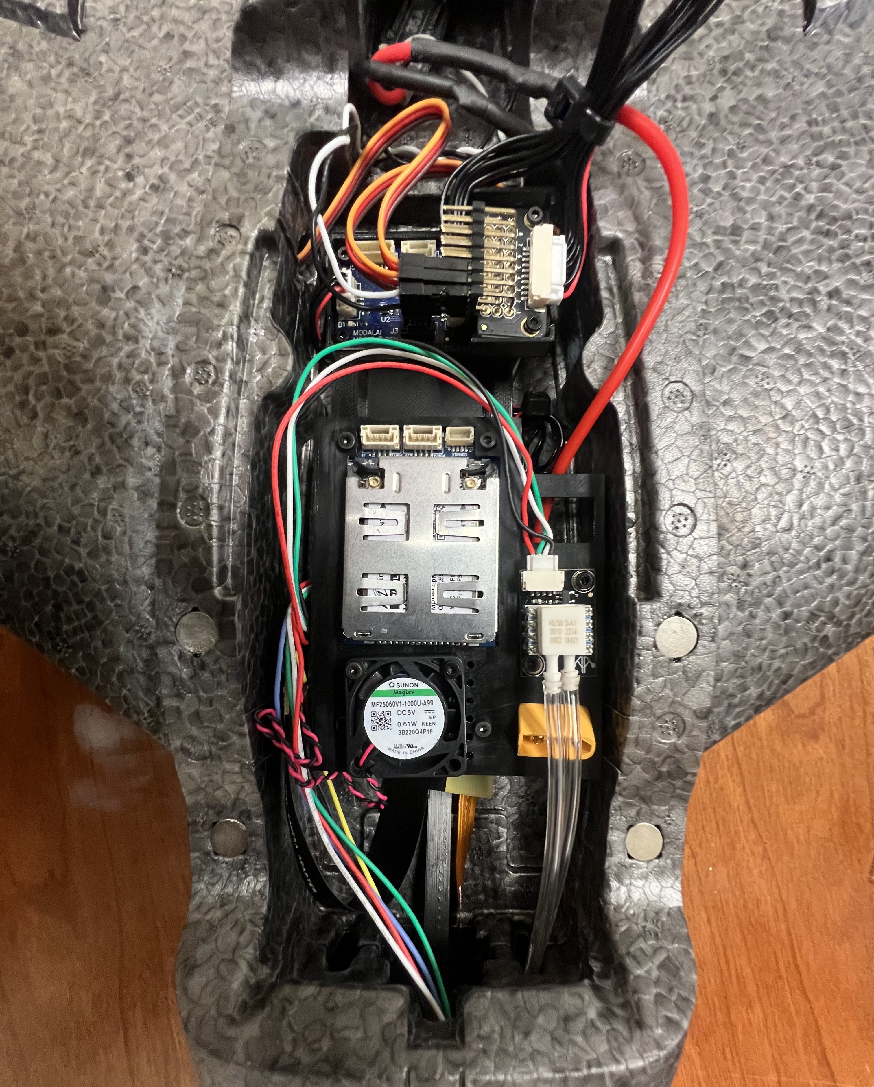
Proceed to place the hardware to look like the following:
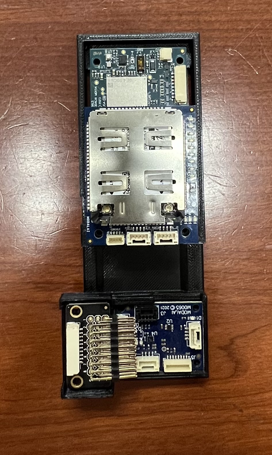
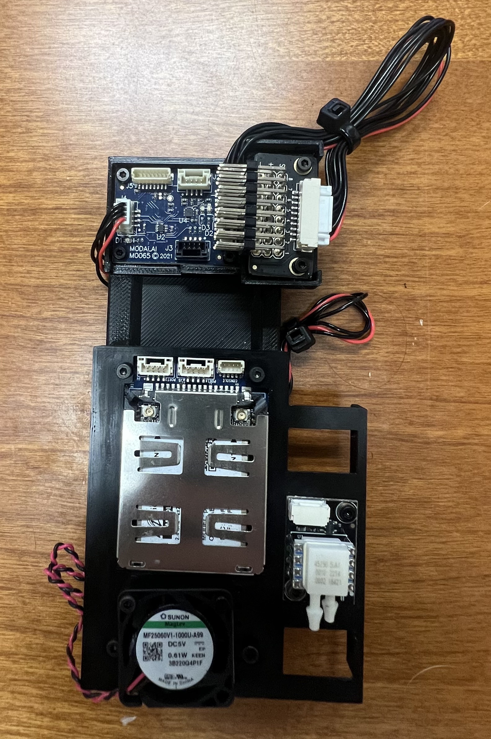
Once everything has been placed correctly, proceed to use M2 sized screws and nuts to tighten the PWM Breakout Board and the VOXL 2 IO board to the bottom of the holster. Once done you can place the top mount case over the VOXL 2 + Microhard + Cooling fan and screw that down as well (Note the fan can be screwed directly into the holes to secure it in place):
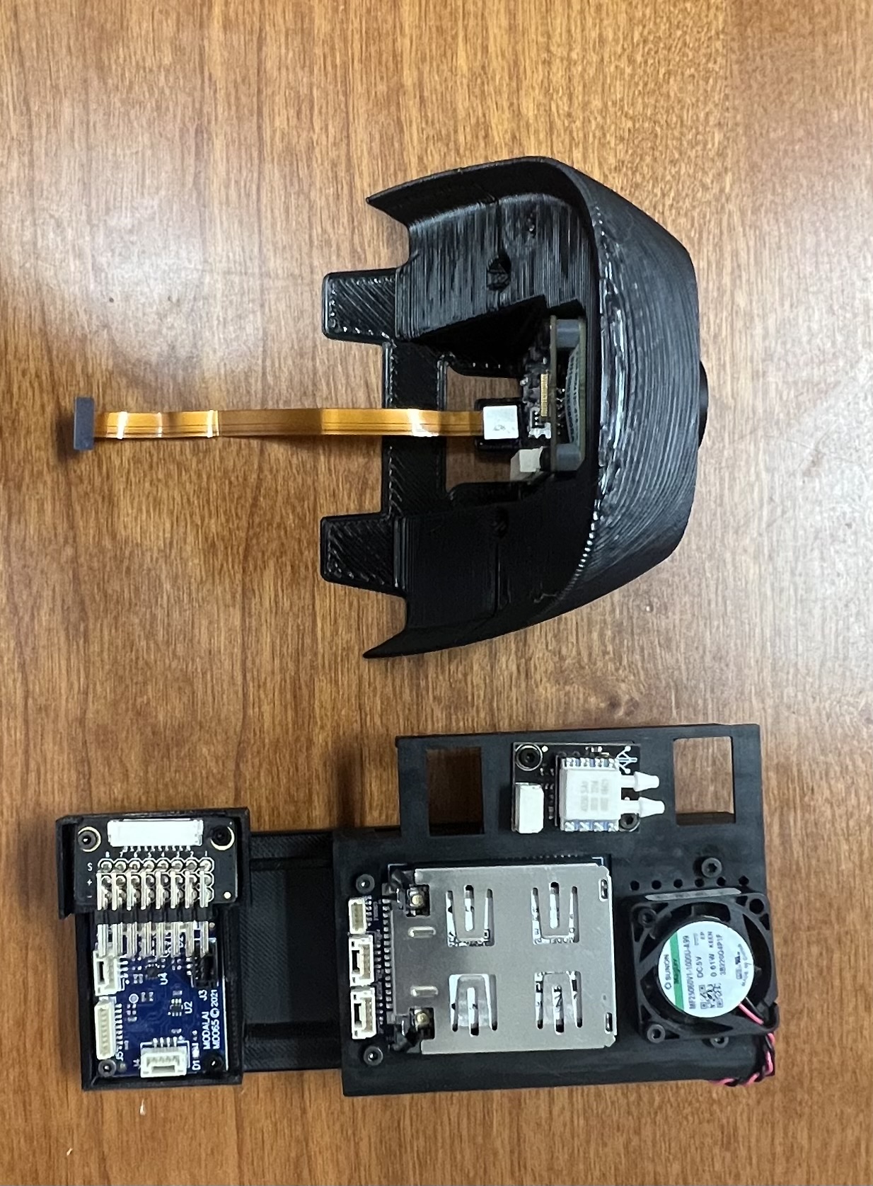
Note the above picture also shows the camera mounts - we will address that later in the instructions.
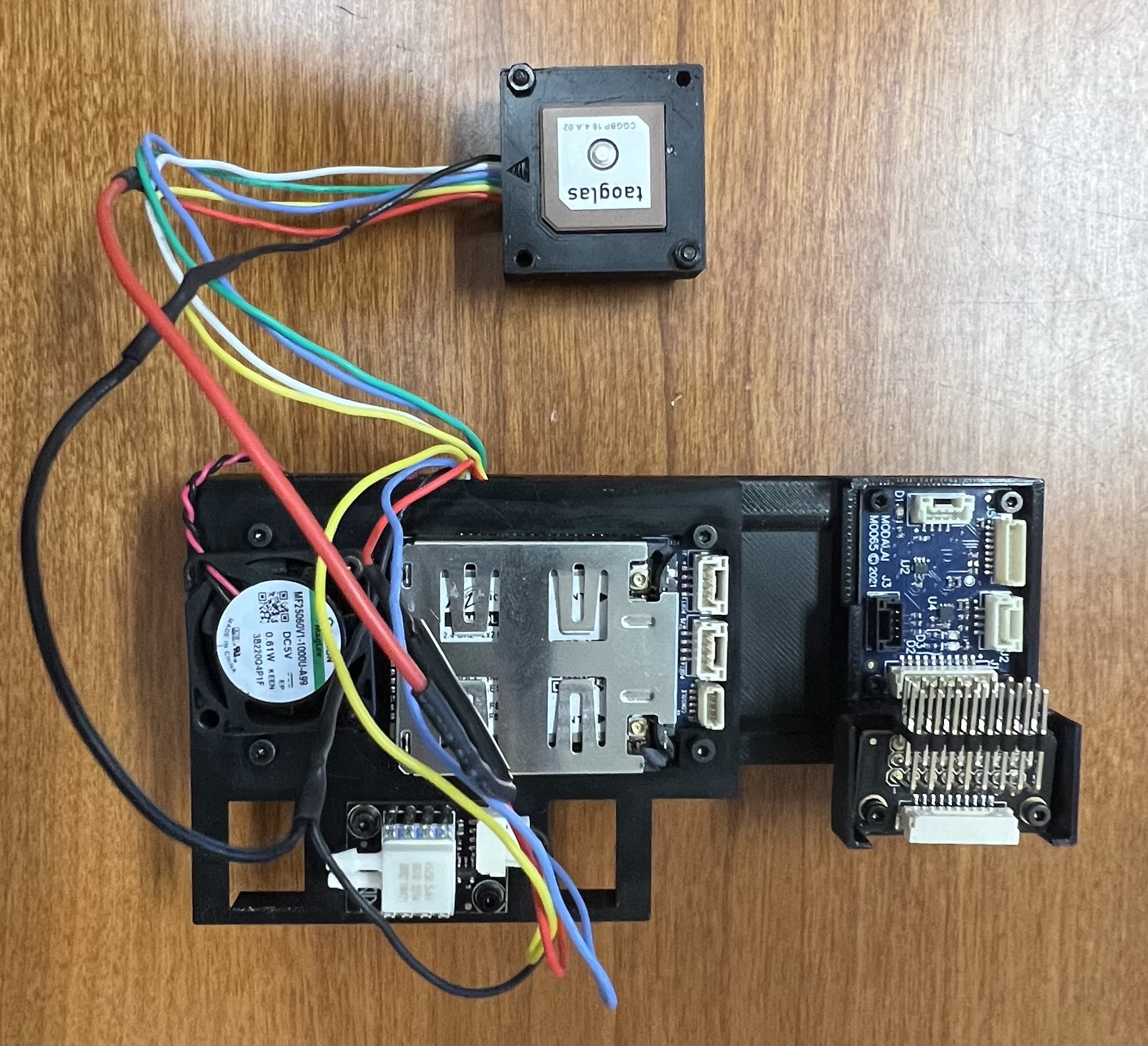
At this point we can flip to the belly of the print once everything has been mounted and place a two camera interposer on J7.
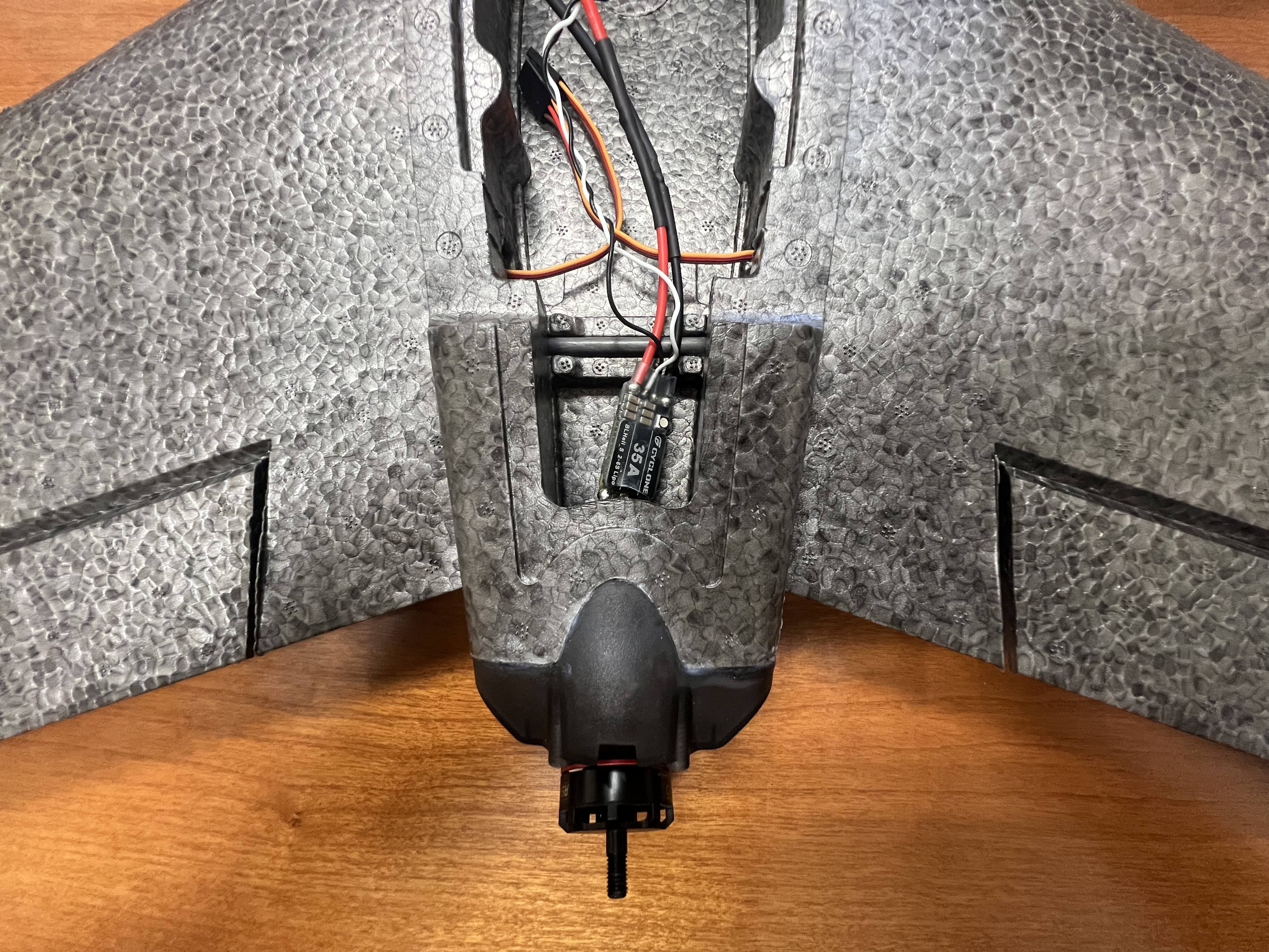
Once secured, we can now start placing the JST wires to connect everything electronically - we will need JSTs to connect the VOXL 2 to the VOXL 2 IO, the VOXL 2 to the airspeed and gps, and then a JST to attach the VOXL 2 IO to the PWM Breakout board.
JST Number 1: 12 Pin JST endpoint that plugs into J19 on the VOXL 2 that goes to a 6 pin JST for the GPS and a 4 Pin JST for the airspeed JST Number 2: 4 Pin JST endpoint that plugs into J8 on the VOXL 2 and goes into another 4 pin JST on the VOXL 2 IO JST Number 3: 10 Pin JST that goes from the VOXL 2 IO to another 10 pin JST that goes into the PWM Breakout board.
You can follow the wiring guide here: D0015
Once everything is soldered up and connected, it should look like the following:
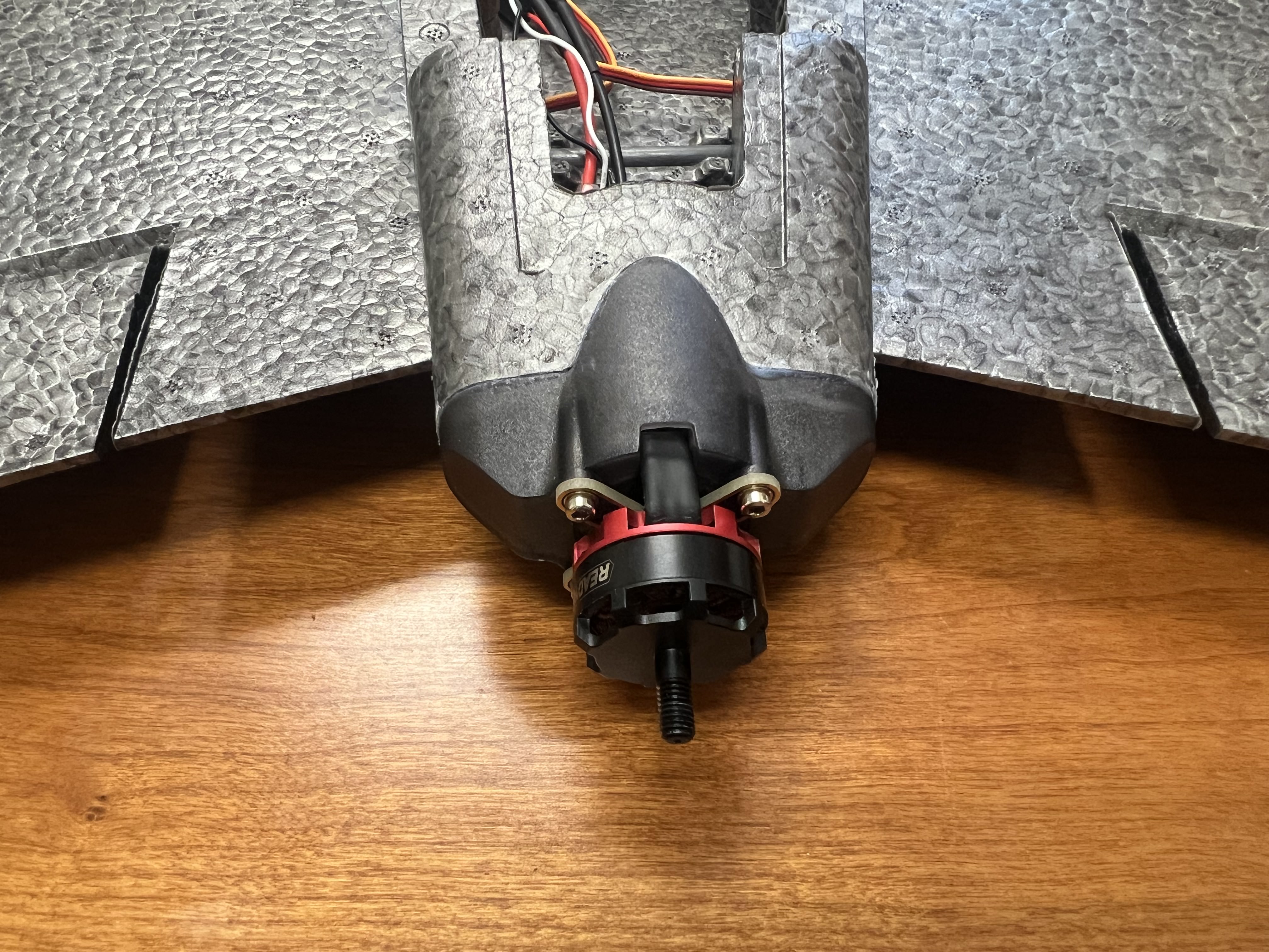
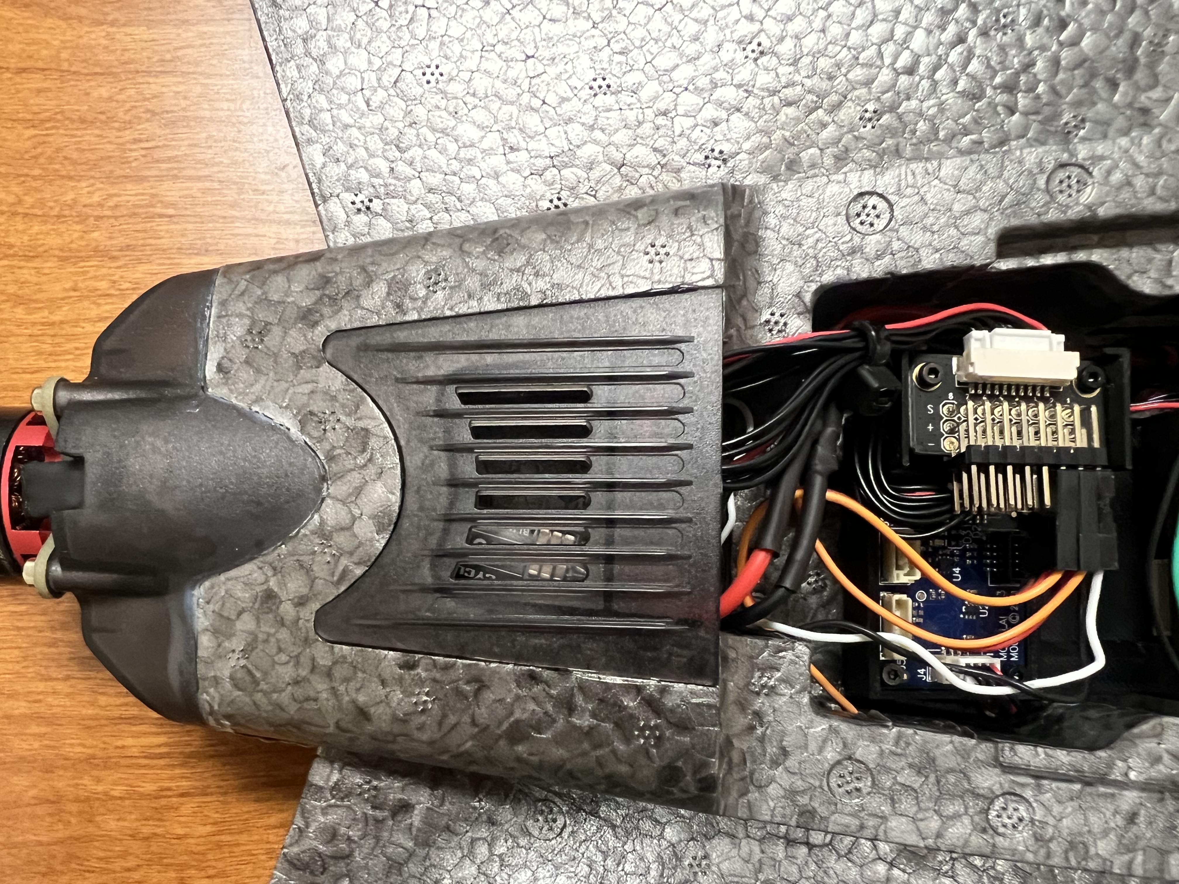
We will now be focusing on the motor, esc, servos, and camera mounts. Proceed to grab you 2205 KV based motor and your 35 AMP 2-6S esc and solder the two together:
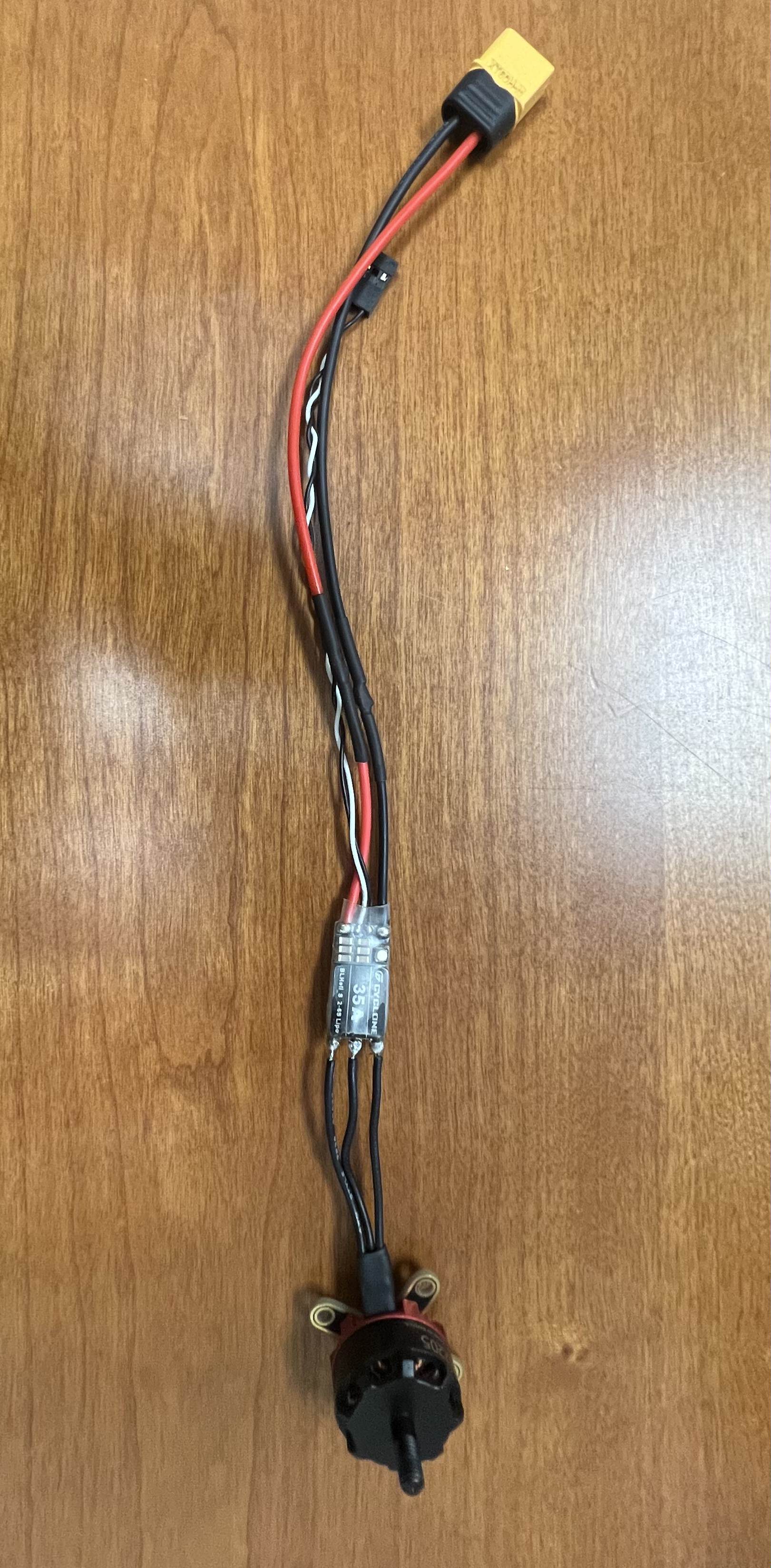
At this point, we can now force the esc and XT60 endpoint through the hole in the backside of the delta wing in order to get the motor mounted onto the backside where we originally mounted the plastic holder to the frame.
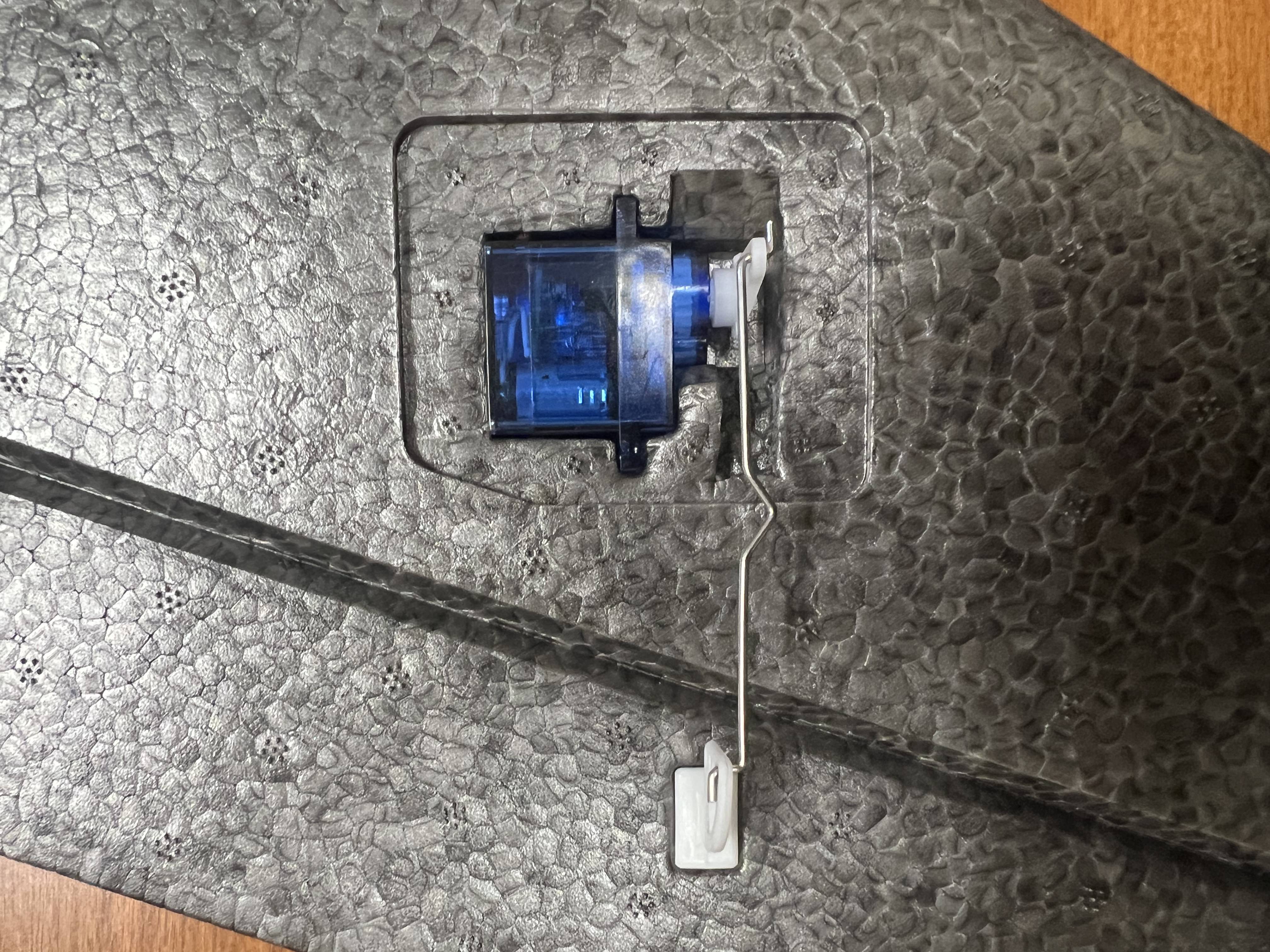
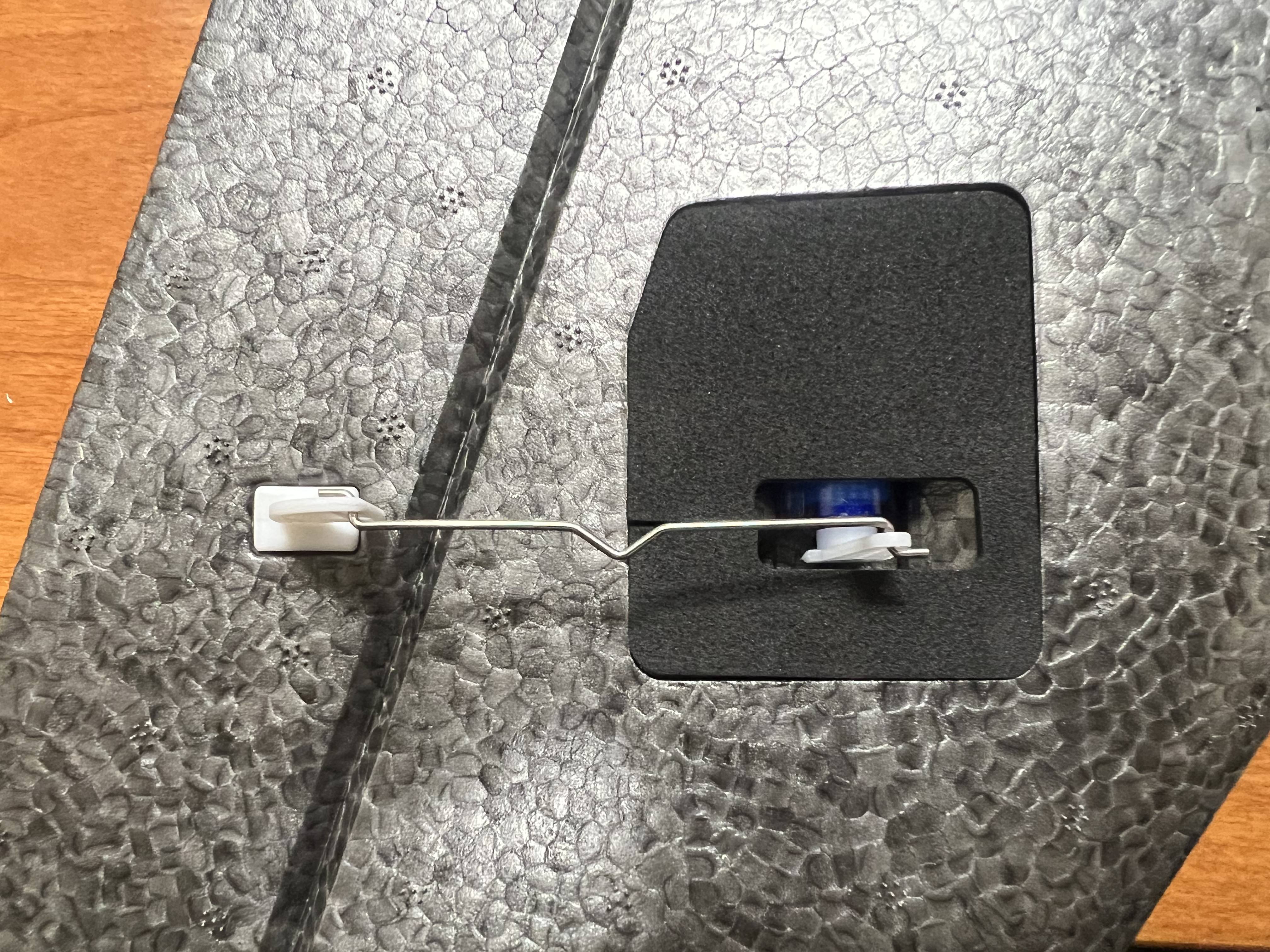
Now that the motors and esc is mounted - we can finish up the servos which should have already been mounted into the wings. We are now going to take the fish hook looking plastic piece and place it into the flaps of the wing. We then can take the long metal wire and fish it through the holes into servo stand:
Once this is done, proceed to place the felt topper onto the wing (this will not effect flight if you do not do this part for easier access to the servos down the line):
Now take the two 3D printed front pieces for the camera mount and glue the two together with the IMX412 placed in the center and the FRAMOS at the top (to ensure that the camera is placed in the upright position - MIPI endpoint should be on the top!):
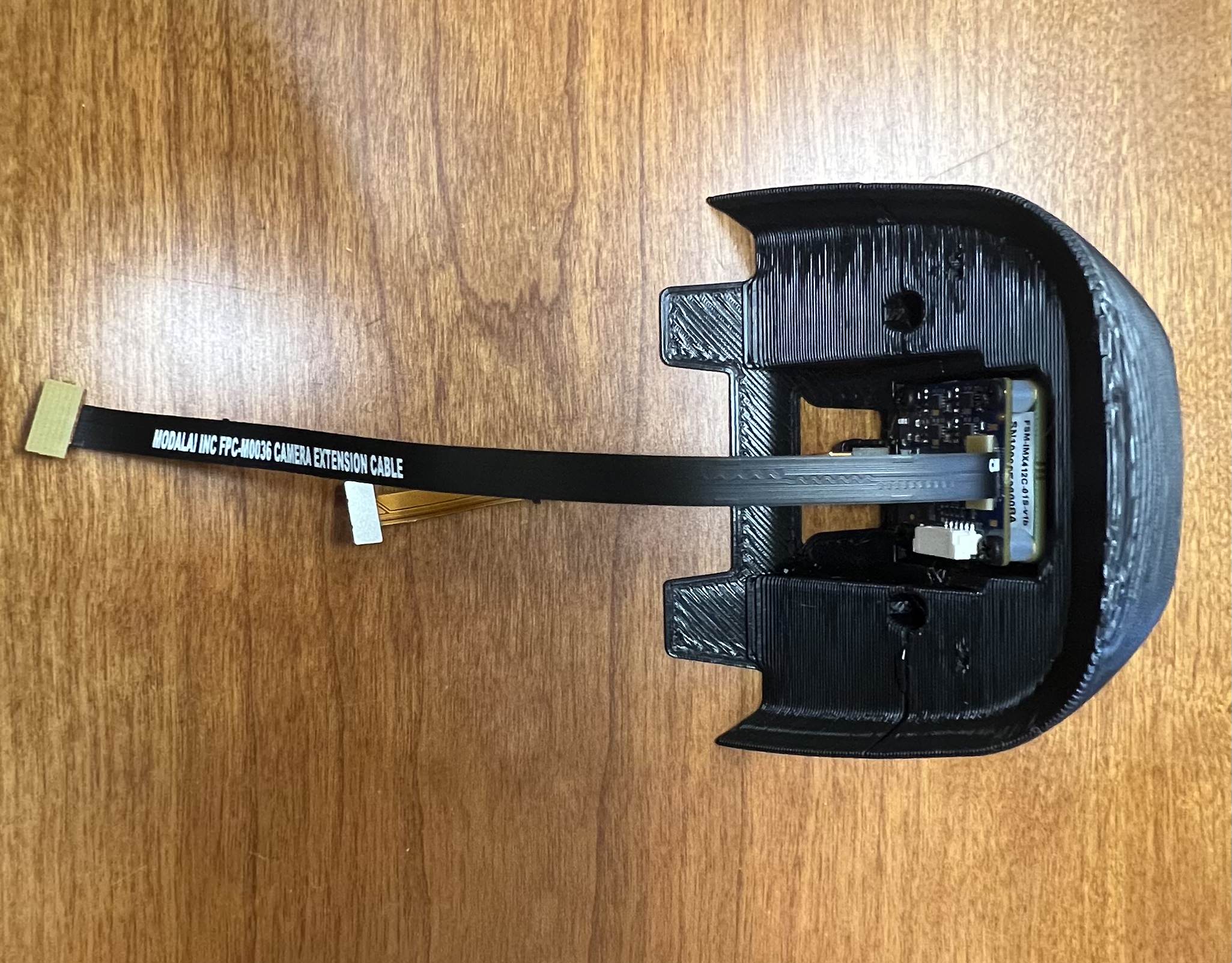
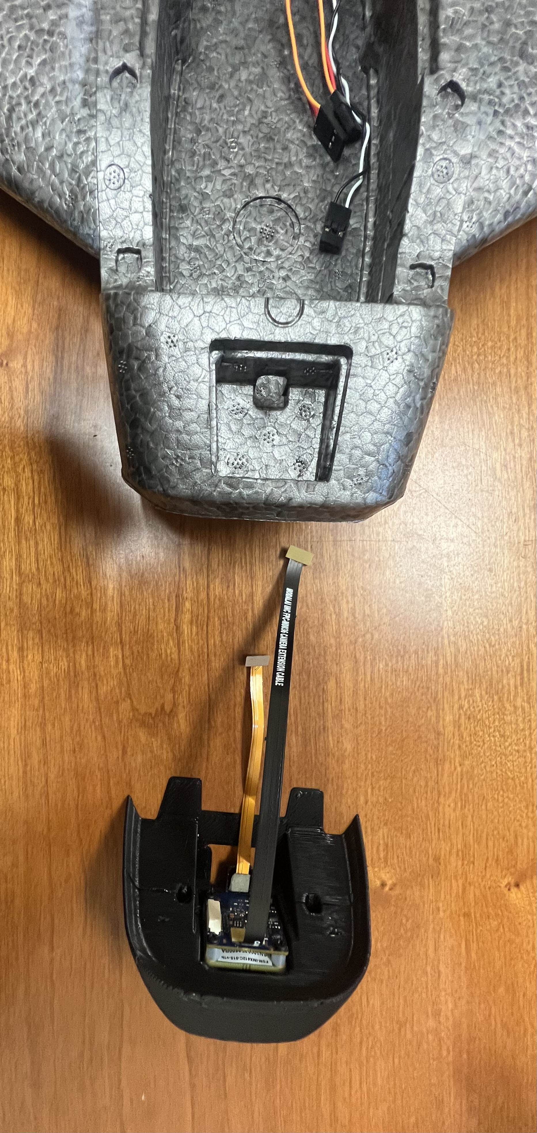
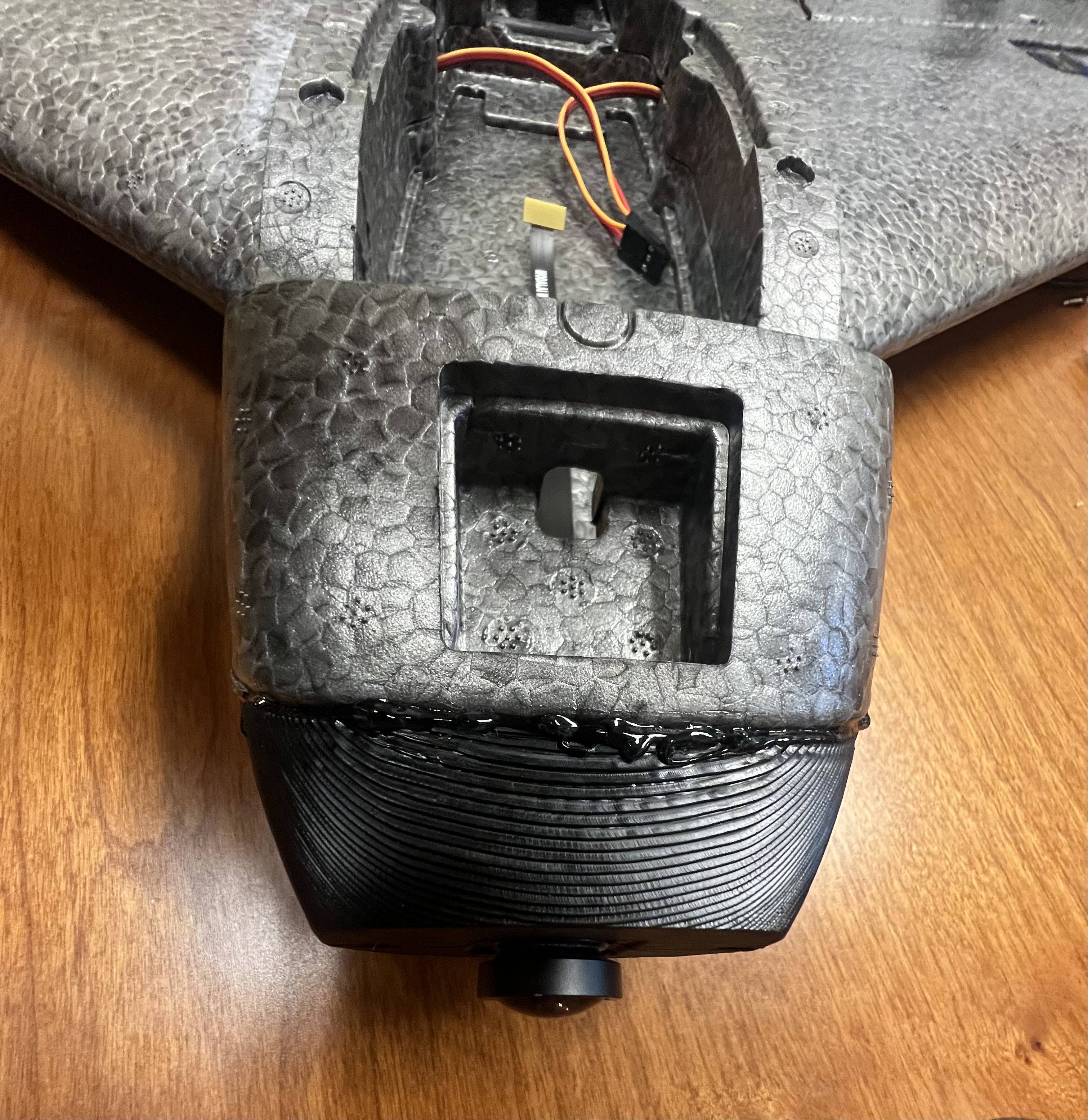
We can then mount this piece onto the delta wing via some super glue:
At this point we can now start assembling the internals of the fixed wing - proceed to take the 3D printed holster with all the I/O mounted, place some double sided VBS tape on the bottom of the case where the 3D print material is exposed, and then firmly press it down into the body of the delta wing near the center. Depending on the size of your battery and where you would like to place it, you can either position the mount further towards the nozzle or back towards the motor:
We will then glue the cover over the ESC section to ensure good airflow:
At this point now, we can finish up the top piece of the fuselage by glueing the magnets provided in the kit to the holes made:
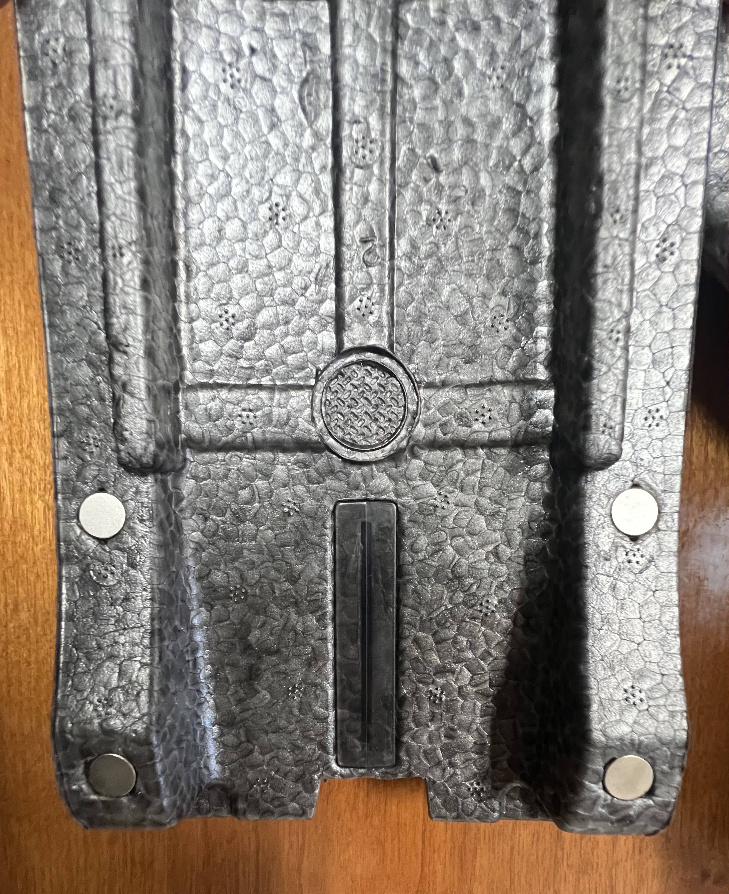
At this point, you can place the opposite (attracted side of magnet) to the holsters inside the fuselage as well and then crown your king!
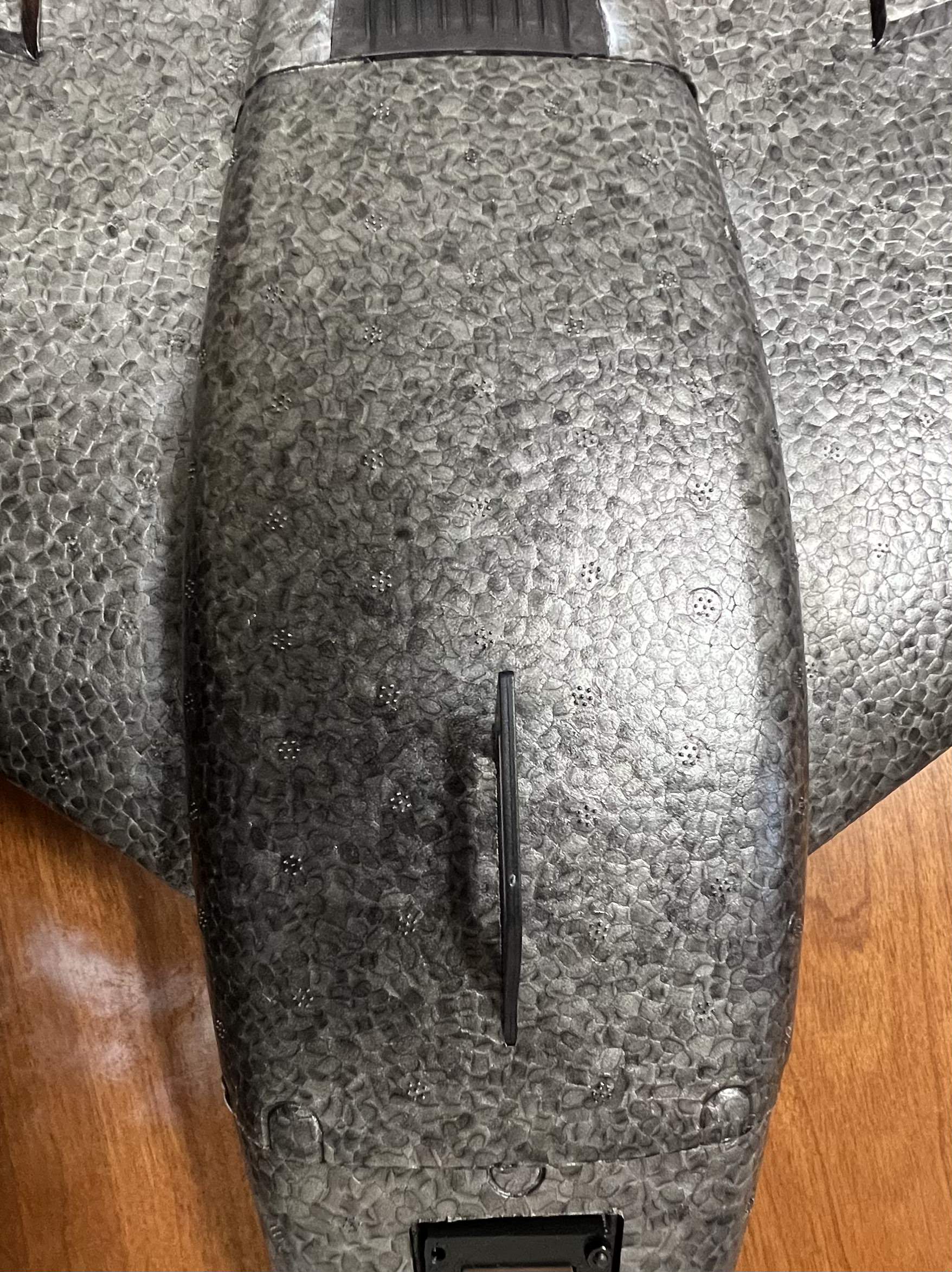
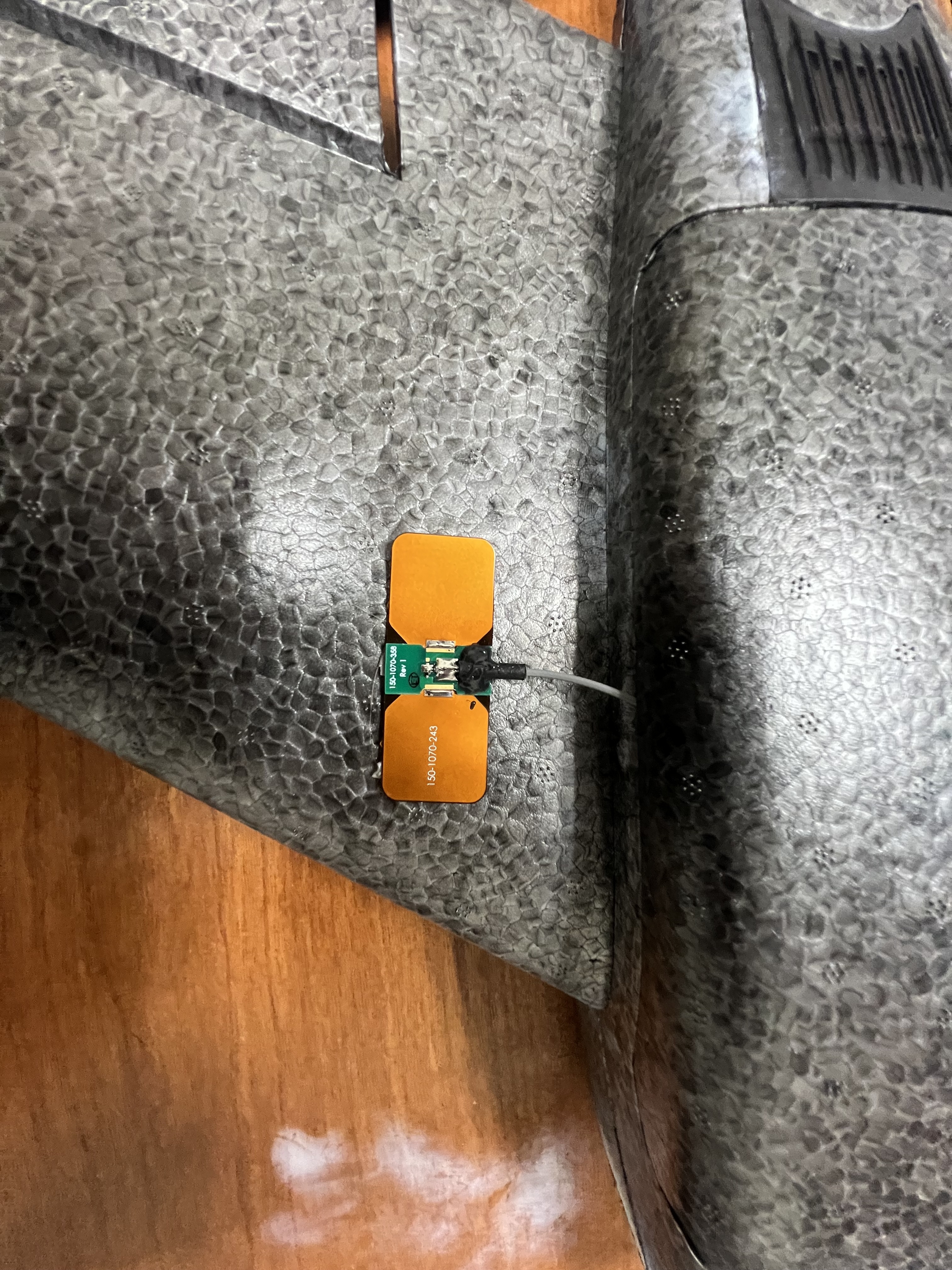
Last thing to do is mount the antennas from the microhard to the wings - proceed to clip the U.FL connectors to the microhard and using vbs tape - tape the antennas to the wings:
At this point you should have a built out and ready to program/configure delta wing! As for placement of the power source, please leverage a 4-Cell LiPO that can be placed in the FRONT of the fuselage. Battery used for flights can be found here