VOXL 2 IO Datasheet
Table of contents
Important Update
Starting in VOXL SDK 1.1.1, the VOXL 2 IO system is being updated, with changes including:
- a new bootloader based on same bootloader as VOXL ESC
- a new firmware based on same firmware as VOXL ESC
- a new
voxl-px4drivervoxl2-ioto support new firmware
Existing VOXL 2 IO may be updated but requires a bootloader update over the debug header. This can be done in the field, or contact ModalAI to arrange a swap out if needed.
For updating the legacy firmware, please see the firmware guide.
Development Kits
| PN | Description |
|---|---|
| MDK-M0065-00 | VOXL 2 IO board only |
| MDK-M0065-01 | VOXL 2 IO board, VOXL2 to VOXL2 IO UART Cable (MCBL-00061), SBus and Spektrum RC cables (MCBL-00021 and MCBL-00005) |
| MDK-M0065-02 | Same as MDK-M0065-01, plus PWM breakout Board and Cable (MCCA-M0022, MCBL-00004) |
VOXL SDK Support
SDK 1.1.1
- SDK 1.1.1 - supported by these documents
SDK 1.1.0 and older
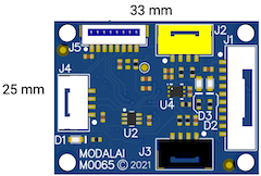
Dimensions
3D Drawings
2D Drawings
25mm x 33mm x 7.2mm
Features
| Feature | Details |
|---|---|
| Weight | 4 g |
| MCU | 72MHz, 32-bit ARM M3 STM32F103C8T6 |
| Memory | 20Kb RAM |
| 64Kbit Flash | |
| Firmware | VOXL 2 IO |
| Inputs | S.Bus |
| Spektrum | |
| Outputs | 3 LEDs (1xRGB) |
| 8 PWM Channels (as of SDK 1.1.1, only 4 channels supported, 400 Hz) |
Block Diagram
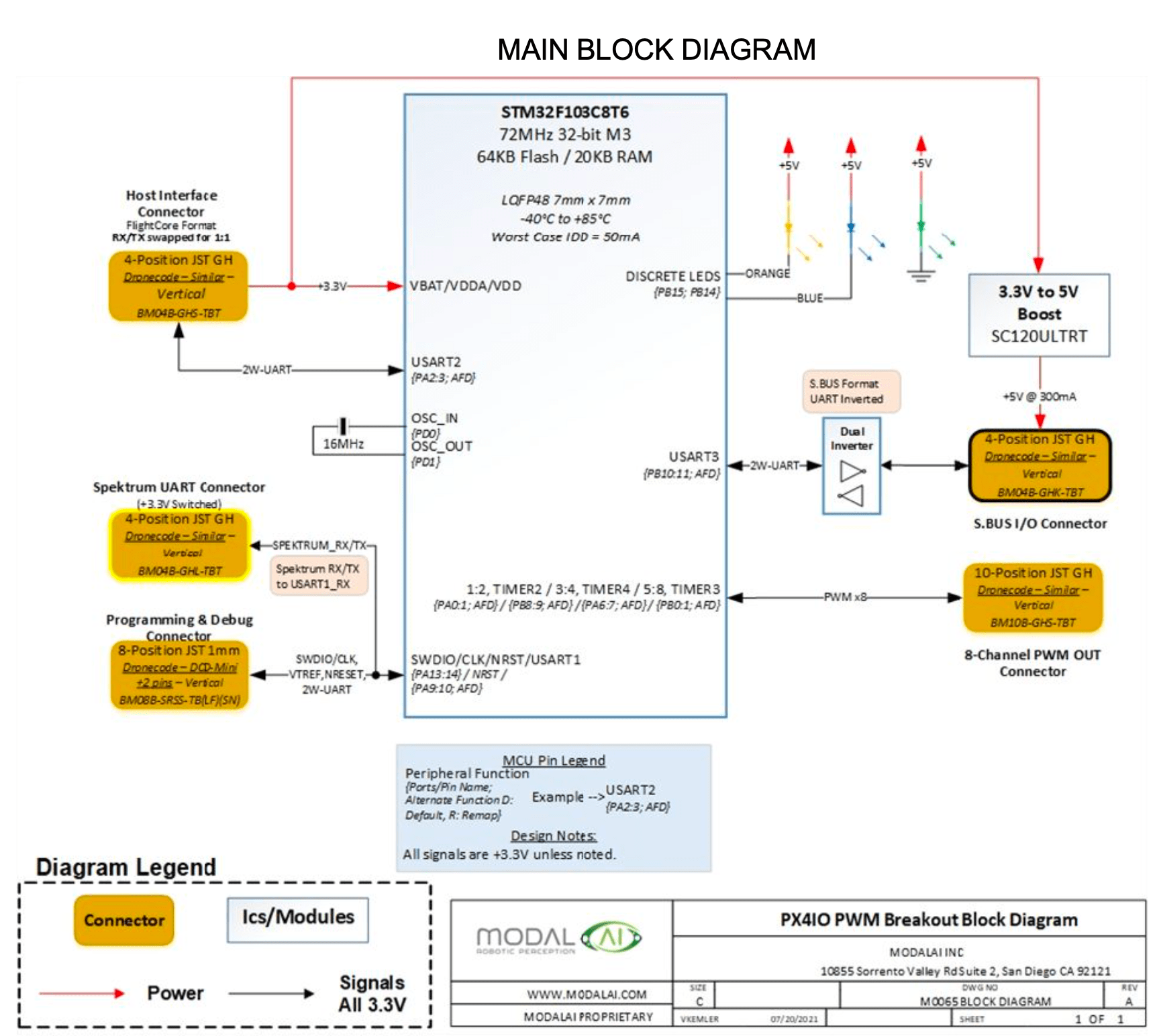 Figure 1
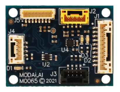
Connector Callouts
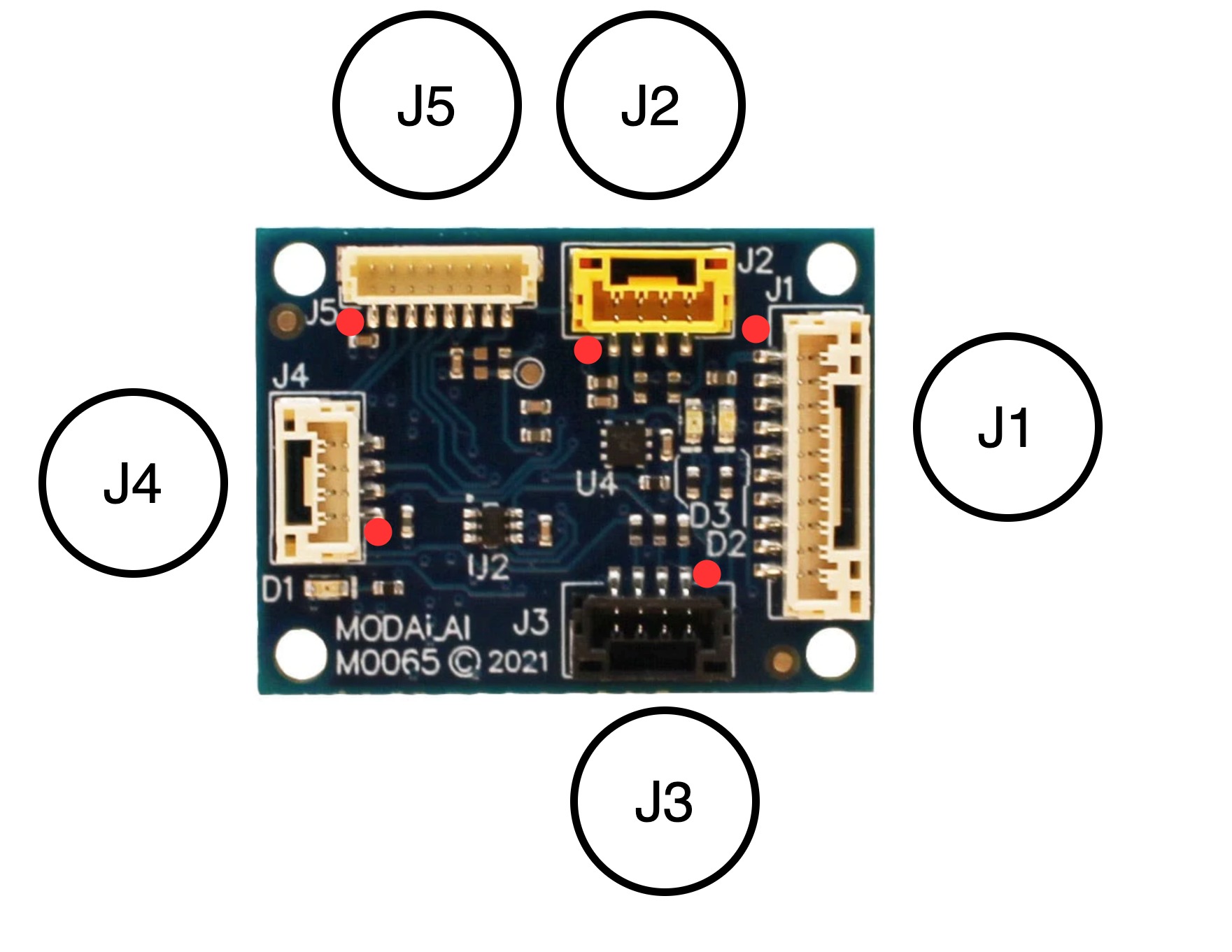
Summary
| Connector | Description |
|---|---|
| J1 | PWM Output |
| J2 | USART1 (future additional RC Input) |
| J3 | S.BUS RC input (USART3) |
| J4 | Host UART and power |
| J5 | Debug/Programming Header |
J1 - PWM Output
NOTE: as of VOXL SDK 1.1.1, only channels 1-4 supported/tested
| Connector | MPN |
|---|---|
| Board Connector | BM10B-GHS-TBT(LF)(SN)(N) |
| Mating Connector | GHR-10V-S |
| Cable | MCBL-00004 - PWM Output Cable, Buy |
| Pin # | Signal Name | Usage / Notes |
|---|---|---|
| 1 | 5P0V_BOOST | Default on, no control unless R10 stuffed, for reference only |
| 2 | IOPWM_OUT_CH1 | |
| 3 | IOPWM_OUT_CH2 | |
| 4 | IOPWM_OUT_CH3 | |
| 5 | IOPWM_OUT_CH4 | |
| 6 | IOPWM_OUT_CH5 | |
| 7 | IOPWM_OUT_CH6 | |
| 8 | IOPWM_OUT_CH7 | |
| 9 | IOPWM_OUT_CH8 | |
| 10 | GND |
J2 - USART1 (future additional RC Input)
Future use. Not supported in VOXL SDK 1.1.1 (use main RC input on VOXL 2 / VOXL 2 Mini)
| Connector | MPN |
|---|---|
| Board Connector | BM04B-GHS-TBT(LF)(SN)(N) |
| Mating Connector | GHR-04V-S |
Color: Yellow
| Pin # | Signal Name | Usage / Notes |
|---|---|---|
| 1 | 3P3V_IO | Controllable |
| 2 | USART1_TX | 3P3V |
| 3 | USART1_RX | 3P3V |
| 4 | GND |
J3 - S.BUS RC Connection
| Connector | MPN |
|---|---|
| Board Connector | BM04B-GHS-TBT(LF)(SN)(N) |
| Mating Connector | GHR-04V-S |
| Cables | MCBL-00064 - S.Bus, (eg. Graupner GR-16), Dupont Style, Buy |
| [MCBL-00065](/cable-datasheets/#mcbl-00065 - S.Bus, (e.g FrSky R-XSR), picoblade, Buy |
Color: Black
| Pin # | Signal Name | Usage / Notes |
|---|---|---|
| 1 | 5P0V_BOOST | Default on, no control unless R10 stuffed |
| 2 | SBUS_OUTPUT_INV | 3P3V, Tx, USART3 |
| 3 | SBUS_INPUT_INV | 3P3V, Rx, USART3 |
| 4 | GND |
J4 - Host UART Input Connector
| Connector | MPN |
|---|---|
| Board Connector | BM04B-GHS-TBT(LF)(SN)(N) |
| Mating Connector | GHR-04V-S |
| Cable | MCBL-00015 - 4pin-JST-GH-to-4pin-JST-GH cable, Buy |
Color: White
| Pin # | Signal Name | Usage / Notes |
|---|---|---|
| 1 | 3P3V_IO | Main voltage input from host |
| 2 | RX from host | |
| 3 | TX to host | |
| 4 | GND |
J5 - Debug/Programming Header
| Connector | MPN |
|---|---|
| Board Connector | BM08B-SRSS-TBT(LF)(SN) |
| Mating Connector | SHR-08V-S |
| Pin # | Signal Name | Usage / Notes |
|---|---|---|
| 1 | 3P3V_IO | Jlink, STLink, etc |
| 2 | UART_2W_DEBUG_TX | nsh |
| 3 | UART_2W_DEBUG_RX | nsh |
| 4 | IOMCU_SWDIO | Jlink, STLink, etc |
| 5 | IOMCU_SWCLK | Jlink, STLink, etc |
| 6 | GND | |
| 7 | PROG_RESET_N | Jlink, STLink, etc |
| 8 | VPP_STM | STM BOOT0 |