VOXL Mini 4-in-1 ESC Datasheet
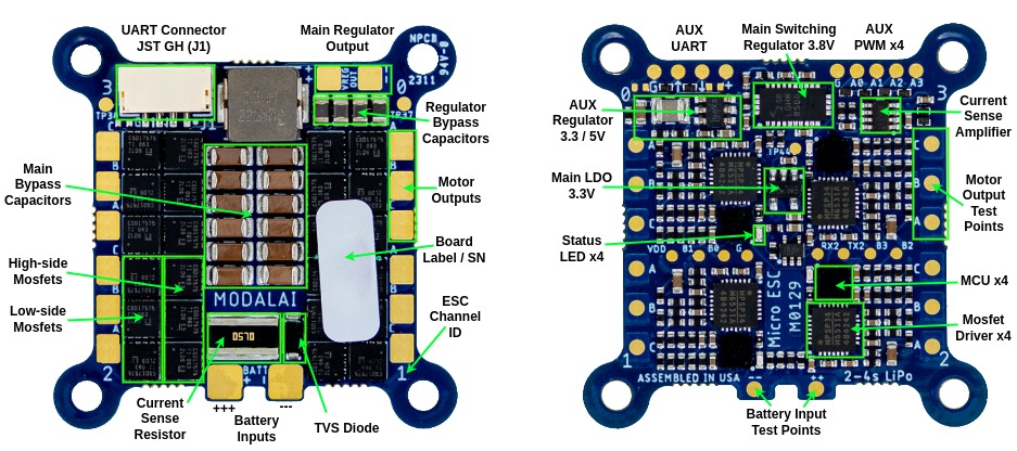
Hardware Overview
This Mini ESC is designed for aerial vehicles under 750g (under 500g for FPV racing applications). For larger slow flying vehicles up to 1500g, please use the VOXL 4-in-1 ESC. For FPV racers exceeding 500g, please use VOXL 4-in-1 FPV ESC.
Dimensions
M0129 VOXL Mini 4-in-1 ESC 3D CAD 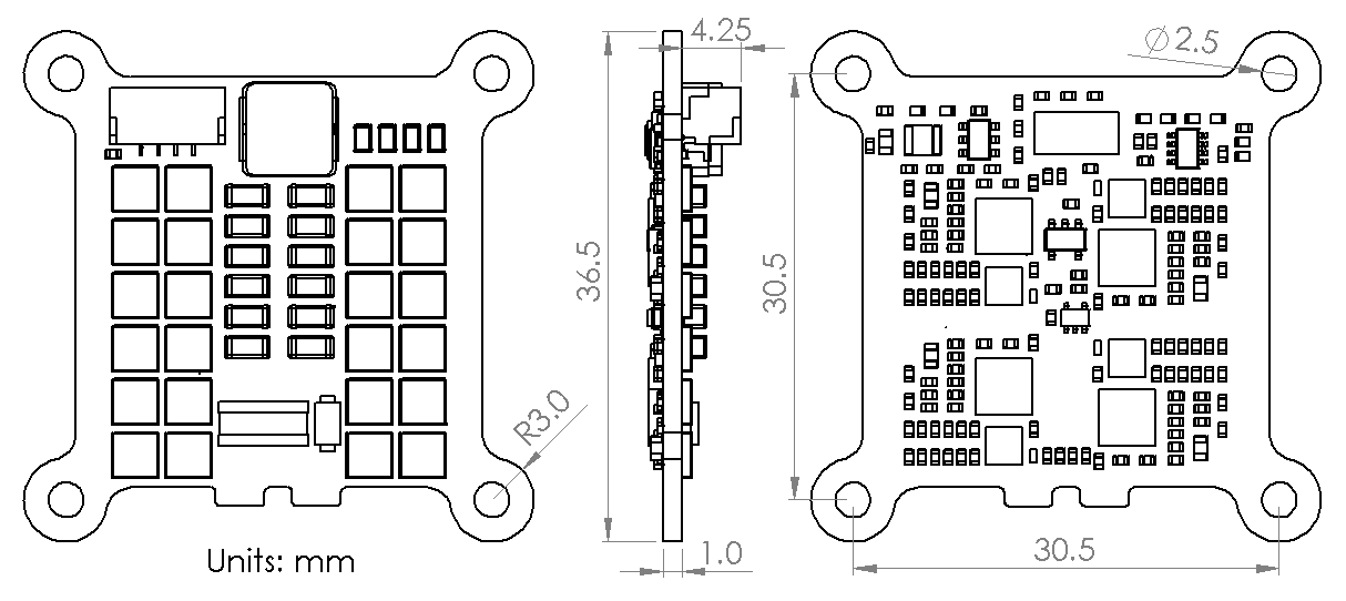
Specifications
| Details | |
|---|---|
| Power Input | 2-4S Lipo (6-18V) : M0129-3 and M0129-5 variants. Supports 4S LiHV |
| 2-6S Lipo (6-26V) : M0129-63 and M0129-65 variants. Supports 6S LiHV | |
| Main Power Output | 3.8V (M0129-3, M0129-63) or 5.0V (M0129-5, M0129-65) @ 5A - (select correct version) |
| AUX Power Output | 3.3V or 5.0V @ 500mA (default 3.3V, SW-controlled) |
| Features | Open-loop control (set desired % power) |
| Closed-loop RPM control (set desired RPM), used in PX4 driver | |
| Regenerative braking | |
| Smooth sinusoidal spin-up | |
| Tone generation using motors | |
| Real-time RPM, temperature, voltage, current feedback via UART | |
| Communications | Supported by VOXL 2, VOXL 2 Mini, VOXL Flight, VOXL and Flight Core |
| Dual Bi-directional UART up to 2Mbit/s (3.3VDC logic-level) | |
| Connectors | 4-pin JST GH for UART communication, solder pads for 3.8V output |
| Hardware | MCU : STM32F051K86 @ 48Mhz, 64KB Flash |
| Mosfet Driver : MP6531 | |
| Mosfets : CSD17575Q3 (N-channel) | |
| Current Sensing : 0.5mOhm + INA186 (total current only) | |
| ESD Protection : Yes (on UART and PWM I/O) | |
| Temperature Sensing : Yes | |
| On-board Status LEDs : Yes | |
| Weight (no wires) : 5.87g | |
| Motor Connectors: N/A (solder pads) | |
| PX4 Integration | Supported in PX4 1.12 and higher |
| Available here | |
| Resources | Manual |
| PX4 Integration User Guide |
Connector Information and Pin-outs
UART Connector J1
- Used for UART communication with the ESC
- Connector on board : BM04B-GHS-TBT
- Mating connector : GHR-04V-S
- Pre-crimped wires : (Digikey) AGHGH28K152 or similar
- 3.3V signals (5.0V input is acceptable)
| Pin > | 1 | 2 | 3 | 4 |
|---|---|---|---|---|
| Function > | N/C | UART RX (IN) | UART TX (OUT) | GND |
Neopixel LED Support
![]()
- Single Neopixel RGB LED outputs is available, up to 32 LEDs
- Use test point labeled ⬇️ (pointing into center of the board) in the AUX UART section of the ESC (AUX UART is not used)
- The I/O pin is connected to ESC ID0
PB6(3.3V levels) - ➕ output provides 3.3V output for the LED array
- Test tools: voxl-esc-neopixel-test.py
- Integration with PX4 is done via
voxl_escdriver andmodal_io_bridge
PWM Inputs / Outputs
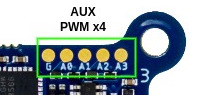
- Four independent PWM input / output pins are available, one pin per ESC channel
- Use test points G (GND), A0, A1, A2, A3
- PWM pin A0 is connected to ESC ID0, A1 -> ESC ID1, and so on (3.3V levels)
- ⚠️Solder carefully to test points and use strain relief to avoid damaging the pads
- PWM input enabled in ESC firmware
39.13or later, PWM output in39.18or later - Operating mode of PWM pins
- Default mode of PWM pins is PWM input. In absence of UART communication, PWM pins can be used to control the ESC power using standard PWM signal (1-2ms)
- Upon detecting any UART communication by ESC, PWM input is disabled until power reset
- PWM output can be enabled by sending specific message to the ESC via UART interface
- PWM output mode specifications
- 3 frequency modes (50hz, 200hz, 400hz)
- enable or disable timeout (0.5s). If timeout is enabled, PWM output will be disabled (set to low state) after 0.5s of no commands
- output range 0-2200 us with 0.05us resolution, special value of 2201us will force HIGH state (can be used as GPIO)
- Test tools: voxl-esc-pwm.py
- this tool can only be used while PX4 is not running, since it needs direct access to the UART port
- Integration with PX4 is done via
voxl_escpx4 driver andmodal-io-server. voxl-send-esc-pwm-cmd- this tool will send a control message to PX4 (
voxl_escdriver) and the driver will forward the PWM command to the ESC
- this tool will send a control message to PX4 (
GPIO
- Available in ESC firmware
39.19or later - Test tools: voxl-esc-gpio.py
| Signal Name | MCU Pin | Function |
|---|---|---|
| AUX_VREG_ENABLE | CH0 PC13 | AUX 3.3 / 5.0V Regulator Power Control |
| AUX_VREG_ADJUST | CH0 PC14 | AUX 3.3 / 5.0V Regulator Voltage Select (disabled) |