How to use VL53L1CX Rangefinders with VOXL 2
The VOXL 2 SDK supports MPA integration of VL53L1X & VL53L1CX mini time-of-flight rangefinders. A single rangefinder is included in the Starling 2, Starling 2 Max, and PX4 Autonomy Dev kits facing down for integration into the autopilot for altitude sensing. Up to 8 can also be supported for custom applications using a TCA9548A I2C Multiplexer.
Table of contents
- Wiring
- voxl-rangefinder-server Configuration
- Inspecting Data
- Data Format
- voxl-vision-hub Obstacle Avoidance
- PX4 Autopilot Height Estimate Integration
Wiring
voxl-rangefinder-server runs on the applications processor and therefore requires an I2C port connected to the applications process, not the SLPI. Therefore you cannot use port J19 on the VOXL 2 board with voxl-rangefinder-server.
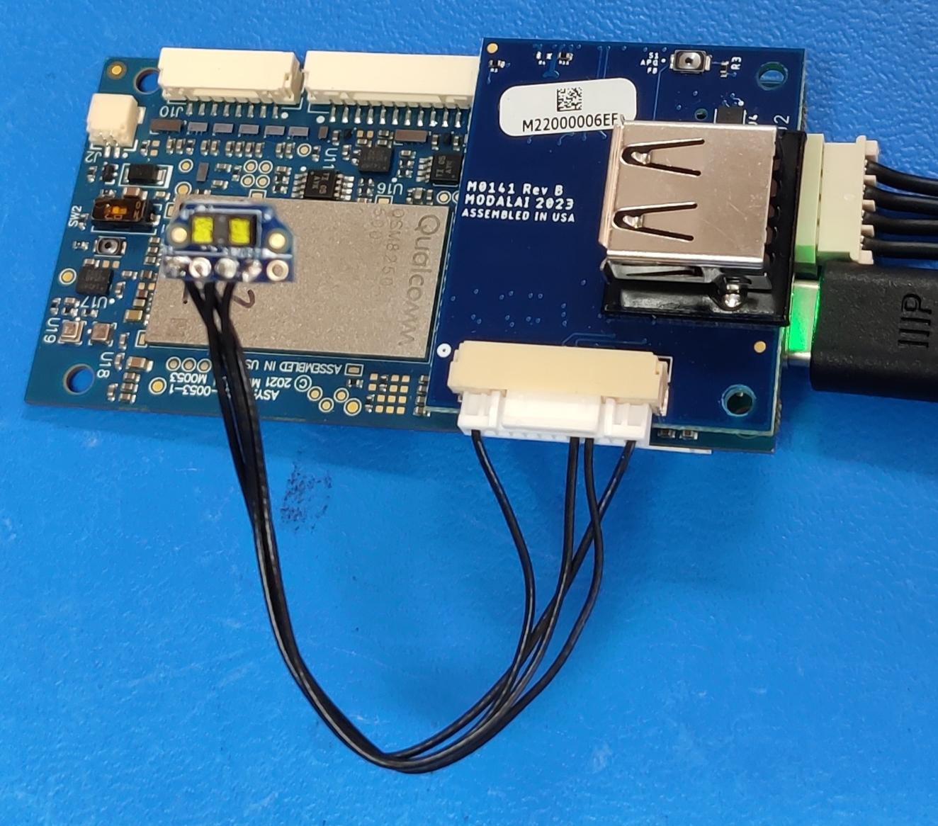
Single Rangefinder using M0141 Expansion Board
The M0141 USB2 Breakout Board exposes power and I2C that can be used with these rangefinders. This is the wiring configuration used on the PX4 Autonomy Dev Kit. This method can also be used with the Starling Development Drone which uses the M0141 breakout board too.
Port J5 on M0141 exposes VOXL 2’s I2C port 1 (/dev/i2c-1). These are 3.3v level signals with 2.2k pullups included on the M0141 board.
| Pin# | Signal | Notes/Usage |
|---|---|---|
| 1 | 3P3V | |
| 8 | I2C9_SDA | /dev/i2c-1 |
| 9 | I2C9_SCL | /dev/i2c-1 |
| 12 | GND |
Configure voxl-rangefinder-server to use this with either:
voxl-configure-rangefinders 1_downward_on_m0141
voxl-configure-rangefinders 1_on_m0141
Single Rangefinder using M0173 Camera Breakout Board
Starling 2 and Starling 2 Max use the M0173 camera breakout board which also exposes a SPI and I2C port designed to be connected to the M0157 Lepton and Rangefinder board.
Port J6 on M0173 exposes VOXL 2’s I2C port 4 (/dev/i2c-4).
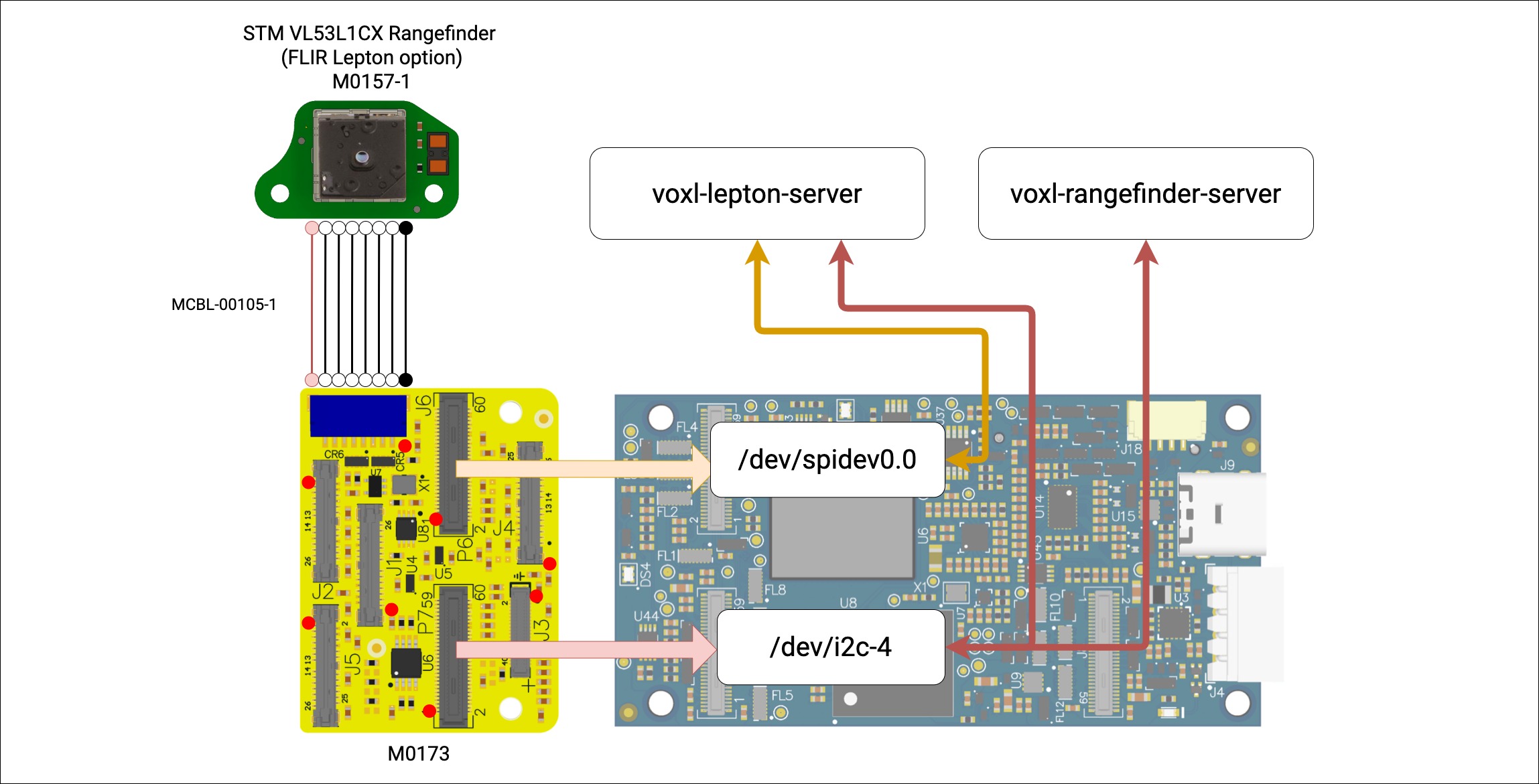
Configure voxl-rangefinder-server to use this with:
voxl-configure-rangefinders 1_downward_on_m0173
This step is run as part of the normal voxl-configure-mpa setup step on Starling 2 and Starling 2 Max.
Multiple Rangefinders on a Multiplexer
Up to 8 rangefinders can be connected via a TCA9548A multiplexer or up to 4 can be connected via a PCA9846 multiplexer. This can be prototyped with breakout boards such as this from Sparkfun.
An example configuration file setup can be generated with the following:
voxl-configure-rangefinders 4_on_m0141
voxl-rangefinder-server Configuration
Use of one of the above configure commands will enable the voxl-rangefinder-server systemd service and generate a default config file to represent the respective hardware setup. Each individual sensor can be configured with a different field of view. All sensors must share the same timing budget as they will all be triggered to start ranging at the same, then data will be read from each sensor sequentially in the order listed in the config file.
The range_max_m, position, and orientation fields for each sensor should also be set correctly in this config file. They are not used by the voxl-rangefinder-server other than to populate the published rangefinder data with the location and orientation of the sensor for convenience of the data subscriber. This data IS used by voxl-vision-hub for obstacle avoidance.
For the M0141 setup above, the following config file is generated. Note when is_on_mux is set to false, the contents of i2c_mux_address and i2c_mux_port are ignored.
voxl2:/$ voxl-configure-rangefinders 1_downward_on_m0141
creating new config file for 1 downward TOF without multiplexer
DONE
enabling  voxl-rangefinder-server systemd service
Done configuring voxl-rangefinder-server
voxl2:/$ cat /etc/modalai/voxl-rangefinder-server.conf
/**
 * Rangefinder Configuration File
 * This file is used by voxl-rangefinder-server
 * please use voxl-rangefinder-server --config {arrangement}
 * to set up this file.
 *
 * FOV for VL53l1X TOF rangefinder is a diagonal FOV in degrees and
 * can be set between 15 and 27 degrees.
 *
 * vl53l1x_timing_budget_ms MUST be one of 20, 33, 50, 100, 200, 500
 * 100 is default
 * vl53l1x FOV options are 15, 20, and 27 degrees
 * default is 27
 *
 * set id_for_mavlink to a valid id (0+) to publish that sensor reading to
 * mavlink as a DOWNWARD sensor for the autopilot to use
 * set to -1 to disable this feature.
 */
{
	"i2c_bus":	1,
	"vl53l1x_timing_budget_ms":	50,
	"id_for_mavlink":	0,
	"sensors":	[{
			"enabled":	true,
			"sensor_id":	0,
			"type":	"TOF_VL53L1X",
			"fov_deg":	15,
			"range_max_m":	3,
			"location_wrt_body":	[-0.02500000037252903, 0.019999999552965164, 0.00800000037997961],
			"direction_wrt_body":	[0, 0, 1],
			"is_on_mux":	false,
			"i2c_mux_address":	112,
			"i2c_mux_port":	0
		}]
}
A longer example config file of using 4 rangefinders on a multiplexer can be generated with voxl-configure-rangefinders 4_on_m0141
{
	"i2c_bus":	1,
	"vl53l1x_timing_budget_ms":	50,
	"id_for_mavlink":	-1,
	"sensors":	[{
			"enabled":	true,
			"sensor_id":	0,
			"type":	"TOF_VL53L1X",
			"fov_deg":	27,
			"range_max_m":	3,
			"location_wrt_body":	[0, 0.027000000700354576, -0.029999999329447746],
			"direction_wrt_body":	[0, 1, 0],
			"is_on_mux":	true,
			"i2c_mux_address":	112,
			"i2c_mux_port":	0
		}, {
			"enabled":	true,
			"sensor_id":	1,
			"type":	"TOF_VL53L1X",
			"fov_deg":	27,
			"range_max_m":	3,
			"location_wrt_body":	[-0.014999999664723873, 0, -0.045000001788139343],
			"direction_wrt_body":	[-0.97399997711181641, 0.22499999403953552, 0],
			"is_on_mux":	true,
			"i2c_mux_address":	112,
			"i2c_mux_port":	1
		}, {
			"enabled":	true,
			"sensor_id":	2,
			"type":	"TOF_VL53L1X",
			"fov_deg":	27,
			"range_max_m":	3,
			"location_wrt_body":	[-0.014999999664723873, 0, -0.045000001788139343],
			"direction_wrt_body":	[-0.97399997711181641, -0.22499999403953552, 0],
			"is_on_mux":	true,
			"i2c_mux_address":	112,
			"i2c_mux_port":	2
		}, {
			"enabled":	true,
			"sensor_id":	3,
			"type":	"TOF_VL53L1X",
			"fov_deg":	27,
			"range_max_m":	3,
			"location_wrt_body":	[0, -0.027000000700354576, -0.029999999329447746],
			"direction_wrt_body":	[0, -1, 0],
			"is_on_mux":	true,
			"i2c_mux_address":	112,
			"i2c_mux_port":	3
		}]
}
This represents a set of sensors being aimed out the sides and rear of a drone, a possible arrangement for obstacle avoidance.
Inspecting Data
Check that the voxl-rangefinder-server is running in the background with one of the following methods:
voxl2:/$ systemctl status voxl-rangefinder-server
voxl2:/$ voxl-inspect-services
Now you can use the voxl-inspect-rangefinder tool to see the data being published. If multiple rangefinders are configured, their distances will be listed on the same line.
voxl2:/$ voxl-inspect-rangefinders

   id  |latency(ms)|distances (m)
 13173 |    26.3   | 2.222
For debugging, you can also run the voxl-rangefinder-server binary from the command line with the debug flag enabled to see more data about the sensor as well as debug messages.
voxl2:/$ voxl-rangefinder-server --debug
=================================================
i2c_bus: 1
has_nonmux_sensor: 1
n_mux_sensors:     0
n_enabled_sensors: 1
vl53l1x_timing_budget_ms: 50
id_for_mavlink:    0
#0:
    enabled:               1
    sensor_id:             0
    type:                  TOF_VL53L1X
    fov_deg:               15.000
    range_max_m:           3.000
    location_wrt_body:     -0.025  0.020  0.008
    direction_wrt_body:     0.000  0.000  1.000
    is_on_mux:             0
    i2c_mux_address:       0x70
    i2c_mux_port:          0

=================================================
initializing i2c bus 1
initializing non-multiplexed tof sensor id 0
read whoami reg 0x010f = 0xeacc
initializing a sensor
using  4 pads, for a diagonal fov of   15.0 deg
done initializing a sensor
finished initializing 1 vl53l1x sensors
mavlink pipe connected
---------------------------
data ready: 1 i=0
mm:  152 signal:  2374 SD:    2 status: 0  Valid Range
---------------------------
data ready: 1 i=0
mm:  149 signal:  2465 SD:    2 status: 0  Valid Range
---------------------------
data ready: 1 i=0
mm:  150 signal:  2468 SD:    2 status: 0  Valid Range
---------------------------
data ready: 1 i=0
mm:  152 signal:  2483 SD:    2 status: 0  Valid Range
---------------------------
data ready: 1 i=0
mm:  149 signal:  2489 SD:    2 status: 0  Valid Range
---------------------------
Data Format
The datatype for each sensor reading is defined in a header owned by the qrb5165-rangefinder-server project and is installed to the file system at /usr/include/voxl-rangefinder_interface.h
Source code available here: https://gitlab.com/voxl-public/voxl-sdk/services/qrb5165-rangefinder-server/-/blob/master/include/voxl_rangefinder_interface.h?ref_type=heads
typedef struct rangefinder_data_t{
	uint32_t magic_number;      ///< Unique 32-bit number used to signal the beginning of a struct
	int64_t timestamp_ns;       ///< Timestamp in clock_monotonic system time
	uint32_t sample_id;         ///< When multiple sensors are sampled at the same time they should share the same sample_id

	int sensor_id;              ///< unique id identifying the sensor from which the sample originated.
	float distance_m;           ///< distance in meters
	float uncertainty_m;        ///< uncertainty in meters. Set negative if unknown.
                                ///< this is calculated as two standard deviations when
                                ///< the sensor reports measurement sigma like vl53l1x

	float fov_deg;              ///< field of view of the sensor in degrees
	float location_wrt_body[3]; ///< location of the rangefinder with respect to body frame in meters
	float direction_wrt_body[3];///< direction vector of the rangefinder with respect to body frame, unitless vector

	float range_max_m;          ///< Maximum range of the sensor in meters
	int type;                   ///< Rangefinder type, e.g. RANGEFINDER_TPYE_VL53L1X
	int reserved;               ///<  reserved for future use
} __attribute__((packed)) rangefinder_data_t;
The server publishes this data on the rangefinders pipe. The voxl-inspect-rangefinders tool serves as a good example of reading this data and can be found here https://gitlab.com/voxl-public/voxl-sdk/services/qrb5165-rangefinder-server/-/blob/master/tools/voxl-inspect-rangefinders.c?ref_type=heads.
voxl-vision-hub Obstacle Avoidance
voxl-vision-hub also serves as a good example of subscribing to rangefinder data. In the following function, it takes groups of rangefinder data and using the timestamp, field-of-view, location, and orientation of the data, projects points into 3D space for integration into the filtered obstacle point cloud. This 3D data can be viewed in voxl-portal as the voa_pc_out pointcloud.
PX4 Autopilot Height Estimate Integration
One rangefinder in the config file can be flagged as the downward-facing rangefinder for PX4 by setting the id_for_mavlink field to the chosen sensor id. When set, the data from that one rangefinder will also be published as a mavlink distance sensor message to the autopilot via the mavlink_onboard control pipe. This is enabled by default on Starling 2 and Starling 2 Max.
Validate PX4 is receiving the data by checking mavlink-inspector in qGroundControl.
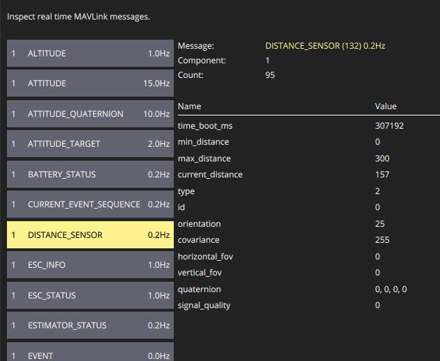
When using voxl-px4 running on the VOXL 2 SDSP as opposed to an external autopilot, you can also inspect the uorb message being published by PX4:
voxl2:/$ px4-listener distance_sensor

TOPIC: distance_sensor
 distance_sensor
    timestamp: 522745702 (0.024082 seconds ago)
    device_id: 9699590 (Type: 0x94, MAVLINK:0 (0x01))
    min_distance: 0.00000
    max_distance: 3.00000
    current_distance: 1.60000
    variance: 0.02550
    h_fov: 0.26180
    v_fov: 0.26180
    q: [nan, nan, nan, nan] (Roll: -nan deg, Pitch: -nan deg, Yaw: nan deg)
    signal_quality: 100
    type: 2
    orientation: 25
To configure how PX4 uses this data, see the PX4 parameter reference. A few relevant parameters are as follows:
EKF2_RNG_CTRL: set to 1 to enable integration of the rangefinder data into EKF2's height estimate
EKF2_HGT_REF: set to 2 to use the rangefinder as the primary height reference.