Table of Contents
- Voxl Mini Tof Server Description
- Usage
- Configuration
- Configuration Tool
- Manual Configuration
- Location
- Direction
- FoV Degree
- Ranging Frequency
- Target Order
- Fanout
- Hardware Setup
- voxl-mini-tof-devices
Voxl Mini Tof Server Description
Creates a server which reads from a config directory and constantly reads and sends rangefinder data as a point cloud on the pipe rangefinder_pc. It first checks for a configuration file at /etc/modalai/voxl-mini-tof-server.conf. Since a process can only use one i2c bus at a time, if multiple rangefinder configurations exist on seperate i2c buses then multiple .conf files can instead be placed in the directory /etc/modalai/voxl-mini-tof-server.conf.d. The server will then create a seperate process to serve each configuration file and each bus.
NOTE: Each configuration file in the voxl-mini-tof-server.conf.d directory MUST use a seperate i2c bus or hardware conflicts will ensue.
If the /etc/modalai/voxl-mini-tof-server.conf file is used, the conf directory will be ignored and only one output pipe, rangefinder_pc, will be created. If multiple configuration files exist, a seperate pipe, rangefinder_pc_x, will be created for each file where “x” is an unspecified integer.
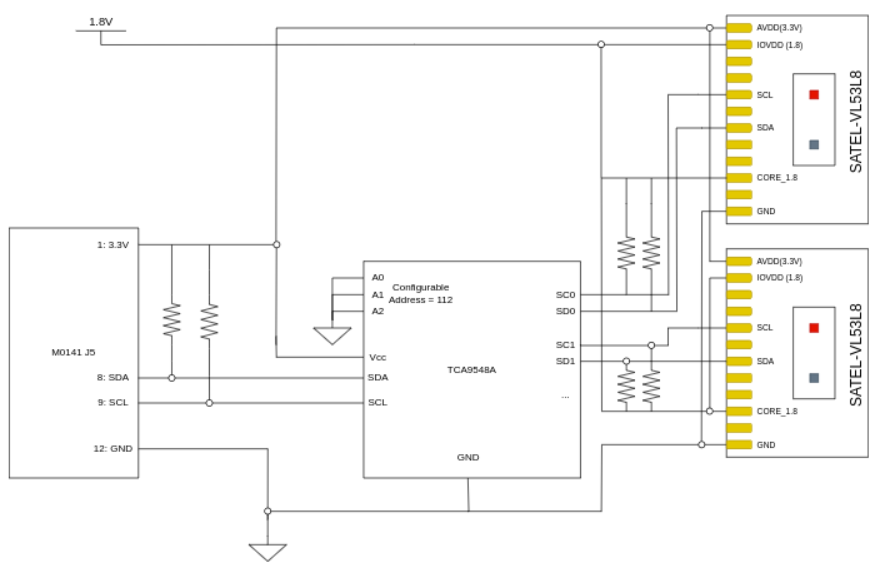
The server can manage any number of sensors as long as they are connected through a TCA9548A i2c mux (or compatible alternative). If sensors are connected to a multiplexer, up to one can also be directly connected to the i2c bus.
Usage
Use either the configuration wizard or systemctl start voxl-mini-tof-server to start the service in the backgroud. You can check on the service’s status with voxl-inspect-services.
ls /run/mpa | grep rangefinder_pc will list any open rangefinder pipes, you can use voxl-inspect-points to inspect the data output from the pipes.
The pointcloud can be visualized in the portal by going to the pointcloud dropdown and selecting rangefinder_pc.
Configuration
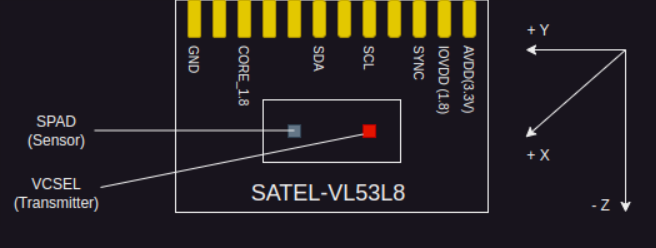 The readings come from the SPAD array, which is on the left side of the sensor (shown in diagram above) so the configured location and orientation must be relative to that sensor. The default orientation of the sensor is shown in the diagram above. The location and orientation of the sensors must be configured precisely.
Configuration Tool
If a known hardware configuration is used, the configuration can be loaded with the configuration wizard. Start the configuration wizard with the command “voxl-configure-mini-tofs -i”. Use the wizard to add the configuration for your hardware if it is listed as an available option. Multiple configurations can be configured together using the add option.
After the configuration is set, use the enable option to start the service and load the configuration.
Use voxl-inspect-points {rangefinder_pc, rangefinder_pc_1, ...}, or view the pointcloud in the portal to check that the server is working correctly.
The configuration tool can also be used in a non-interactive mode to get available configurations and to set the active configuration.
voxl-configure-mini-tofs -l: Lists the names of available configurations.
voxl-configure-mini-tofs -s {configuration name} [configuration name...]: Sets the active configuration to the file(s) with conf_name equal to the following argument(s).
Manual Configuration
Each configuration file is formatted as a JSON object. The top-level object should have the following fields:
i2c_bus(integer)id_for_mavlink(integer)sensors(array of sensor objects)conf_name(string)
The sensors array consists of objects with the following fields. Empty fields will use defaults:
enabled(boolean:true,false)sensor_id(integer)type(enum:TOF_1X33LGC,TOF_1X33L7CX,TOF_1X33L3X)fov_deg(integer, horizontal FOV)location_wrt_body(array[float, float, float])direction_wrt_body(array[float, float, float])is_on_mux(boolean:true,false)i2c_mux_address(integer, default112)i2c_mux_power(integer)ranging_freq_hz(integer)ranging_mode(enum:Continuous,Autonomous)ranging_resolution(integer,2^nwherenis resolution)integration_time_ms(integer)sharpener_pct(integer)target_order(enum:Closest,Strongest)fovea_resolution(integer,2^n; disabled if0or< ranging_resolution)fovea_enr(boolean, not yet implemented)
Location
The location is specified in millimeters from the center of gravity of the robot.
Direction
The direction is specified as a tait-bryan rotation from the forward facing vector of the drone.
FoV Degree
Currently the FoV has to be set manually for each sensor. This field is also used for changing the FoV on sensors like the VL53L1X which support variable FoV. For the VL53L7CX it should always be set to 60 and for the VL53L8CX it should always be set to 45.
Ranging Frequency
This is used to set the frequency of the ranging measurements. The maximum values depending on the ranging resolution and the type of sensor, please consult the individual sensor’s datasheets for more information on possible values.
Target Order
The sensors are capable of measuring a number of targets in a given zone, if the number of targets detected is greater than the number of targets read per zone (currently hardcoded to 1), then the points which are generated depend on the order the targets are reported in. Future updates will support multiple targets being reported per zone.
Fanout
If the fanout_resolution is set to a value greater than the ranging_resoltion, more points will be estimated within the FOV based on the actual measurements. This is used to give the mapping software a better indication of the full field of view, especially with the VL53L1X sensors which are only capable of measuring one zone over a relatively large FOV.
Hardware Setup
voxl-mini-tof-devices
This library contains code to abstract away direct interaction with the vl53 sensors and provides a high-level interface for creating, starting, and reading from them. Include the header vl53.h to use the sensors.