M0184 Software Guide
Table of contents
Summary
Components
| Component/Repo | Notes |
|---|---|
| elrs-build-docker | Docker container that can clone/build FW with ease |
| VOXL SDK | Used to deploy all required software/firmware components to VOXL / ELRS hardware |
| ExpressLRS | Fork of Express LRS supporting ELRSv1 (goal is to mainline) that runs on ELRS v1 (M0184) |
| crsf_rc | PX4 driver running in voxl-px4 that communicates over CRSF to ELRS v1 hardware |
| voxl-elrs | VOXL2 command line utility, used to update FW/config on ELRS v1 from VOXL2, part of the SDK |
| FW bootloader | Open source ExpressLRS bootloader |
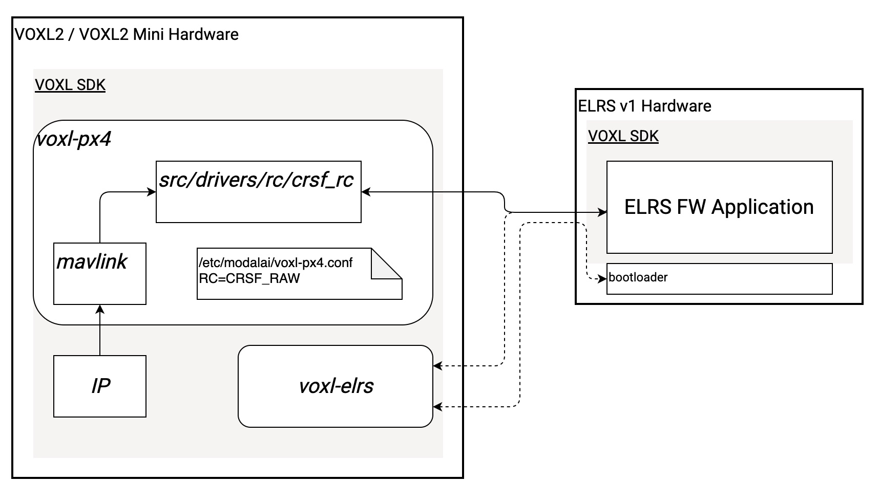
Software Block Diagram
Use Cases
voxl-elrs Utility
See voxl-elrs utility on target.
Setting Up PWM Pins
Up to four PWM pins can be configured. Examples of config files that can be loaded in:
Setting PWM Over IP
Summary
SDK 1.5.0 or newer required.
Using a Transmitter as a USB joystick, you can setup a switches to buttons and map these to PWM channels physical on the M0184 radio, supporting the ability to set PWM values over IP connections.
PX4 Params
RC_CRSF_BUTTON1 through RC_CRSF_BUTTON8
- Selects a button as input that will be mapped to a PWM channel output
- NOTE : If you notice PWM behavior which resembles correct funtionality but shifted over by 1, re-assign current parameter values to one button higher.
RC_CRSF_PWMCHN1 through RC_CRSF_PWMCHN8
- Selects a PWM channel output for button1 through button8
RC_CRSF_PWMVAL1 through RC_CRSF_PWMVAL8
- Selects a PWM channel output value for button1 through button8. See PWM value mappings here.
Transmitter setup
If using a normal RC transmitter as a USB Joystick such as a RadioMaster Zorro there is a little bit of manual setup required in order for QGC and other applications to recognize the buttons correctly. If using a Logitech USB controller or other where buttons enumerate automatically this section can be skipped.
The following instructions were compiled using a RadioMaster Zorro connected via USB-C to the host PC.
edgeTX v2.10+ is required, in order to validate FW version:
- Press the
SYSbutton, which will bring you to theTOOLSpage - Press the
PAGE <button to navigate to theVERSIONpage - Confirm edgeTX version is >= v2.10
In order to upgrade FW version, follow the instructions here: https://manual.edgetx.org/installing-and-updating-edgetx/update-from-opentx-to-edgetx-1 https://manual.edgetx.org/edgetx-how-to/access-dfu-and-bootloader-mode
In order to translate the RadioMaster Zorro’s channel mappings to buttons. do the following:
- Press the
MDLbutton - Press the
PAGE >button once to navigate to theSETUPpage - Scroll all the way to the bottom until you see the
USB Joysticksection - In the
USB Joysticksection, setModetoAdvanced - Set
If.modetoJoystick - Set
Circ. cuttoNone - Navigate to
[Channel Settings]and press enter Set
CH1-CH4toX,Y,Z,rotX(NOTE: The channels used for switches/buttons need to be on channel 9 or above for them to populate in QGC)- In the
[Channel Settings]menu, navigate to the channel you’d like to setup, i.e.CH9 - Set
ModetoBtn - Set
Positionsto either2POSor3POSdepending on the physical switch - Set
Button no.to be the button numbers in QGC that you’d like this switch to populate (NOTE: A 2POS switch requires two buttons (0,1), whereas a 3POS switch requires 3 buttons (0,1,2)) - Return to the home screen
- Press the
MDLbutton - Press the
PAGE >button 5 times to navigate to theMIXESpage - Scroll down to the corresponding channel which was setup, i.e.
CH9 - Select each channel to be used (hold down button) and set the source as the physical switch you’d like to link to the channel
- In order to finalize changes you may need to disconnect and reconnect the joystick or restart QGC
Example Usage
Let’s say a LED bar was soldered to PWM pin P0, and configured for RC channel 7 (for example Stinger Vision FPV).
A PWM value of 1000 turns it off, a value of 1500 turns it to IR, and a value of 2000 turns it to visible light.
On an RC trasnmitter, we configure a 3-pos switch to map to buttons 1, 2 and 3.
In voxl-px4, we set PX4 params using params/v1.14/radio_helpers/pwm_via_elrs.params:
- RC_CRSF_BUTTON1 to 1, RC_CRSF_PWMCHN1 to 7, RC_CRSF_PWMVAL1 to 191* (This maps to 1000)
- RC_CRSF_BUTTON2 to 2, RC_CRSF_PWMCHN2 to 7, RC_CRSF_PWMVAL2 to 992* (This maps to 1500)
- RC_CRSF_BUTTON3 to 3, RC_CRSF_PWMCHN3 to 7, RC_CRSF_PWMVAL3 to 1792* (This maps to 2000)
Failsafe
- When IP connection is connection and lost - TODO
- When IP connection is connected and RC connection gained and lost - TODO