
VOXL 2 Time of Flight (ToF) Sensor Datasheet (IRS2975C)
PMD IRS2975C 240x180 ToF depth module on 40-pin adapter for VOXL 2 via M0173, 106 deg FOV
Table of Contents
- Specification
- Technical Drawings
- Module Connector Pinout
- VOXL 2 Integration
- VOXL SDK
- Image Samples for Sensor
- Hardware Design Guidance
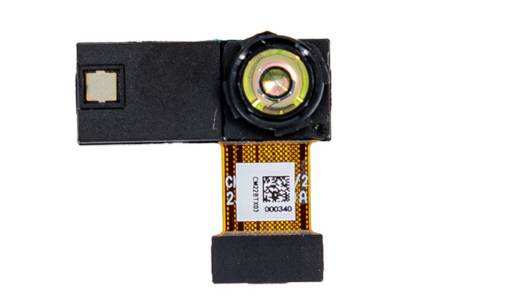
The PMD Time of Flight sensor produces high-fidelity depth mapping indoors up to 6m.
The M0178-1 ToF adapter has a new ModalAI 40-pin format Molex connector and includes a high-power 5V feed as part of the single connector. This is a new connector not used elsewhere in ModalAI, so some integration guidelines are required as explained below.
The M0178-1 adapter can be used with the M0170-1 40-pin extension flex and requires a PCB adapter at VOXL 2 (such as M0172 or M0173) that exposes this new 40-pin Molex from a Camera Group connector.
The M0178 is similar to the M0171, except for the break off mounting tab on the M0171.
Specification
MSU-M0178-1-01 106° FOV
| Specification | Value |
|---|---|
| Part Number | MSU-M0178-1-01 |
| Technology | PMD |
| Rate | 5 - 45FPS in configurable option modes for distance / accuracy / framerate |
| Exposure Time | 4.8 ms typ. @ 45 fps / 30 ms typ. @ 5 fps |
| Resolution | 240 x 180 px |
| FOV (H x W) | 106° x 86°, 138.4° DFOV Max |
| Range | 4 - 6m |
| Illumination | 940nm |
| Depth Resolution | TBD |
| Time Sync | No physical pin, but the frame timestamp is measured with 50ns precision on a single clock. All of the sensors on the VOXL platform are timestamped for computer vision. |
| Power Consumption | TBD |
| Weight | TBD |
| Dimensions | TBD |
| Eye Safe | Yes |
Requirements
| VOXL Version | Supported | Compatible Adapters |
|---|---|---|
| VOXL (APQ8096) | No | None |
| VOXL 2 (QRB5165) | Yes | M0173-1 |
| VOXL 2 Mini (QRB5165) | Future | None |
Current/Power Consumption
The power consumption of the IRS2975 TOF module is a function of several operating conditions:
- operating range mode (long, mid, short or ultra short range)
- FPS:
5, 10, 15, 20, 30, 45, 60 - exposure time of the IR pulses emitted by the sensor
IRS2975 Operating Modes
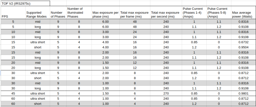 The table above shows most of the available operating modes of the sensor. Different range modes and maximum exposure (per frame) are available depending on the desired FPS.
Maximum power of any mode is around 0.9W which requires a heat spreader and thorough testing to prevent sensor overheating ⚠️
- depending on range mode, there are either 9 measurement phases (8 illuminated) or 5 measurement phases (4 illuminated) per frame
Max exposure per phaseis the maximum length of a single pulse / phase (note there are 8 or 4 of those per frame)- the last column (
Max average power (Watts)) is the maximum power consumed by the emitter in the worst case scenario (auto exposure time = max exposure time)- note that mid range 5FPS at 6ms exposure results in the same power consumption as 10FPS at 3ms exposure due to the same total exposure time (per second)
- if needed, maximum average power dissipation can be reduced by limiting the maximum exposure (per phase) that the auto exposure algorithm (inside the sensor) can apply
- auto exposure works by increasing the IR output power in order to see distant objects or objects with low reflectivity
- by lowerning the maximum allowed exposure time, the worst-case power consumption (and heat dissipation) can be reduced
- the maximum exposure setting is available in
voxl-camera-server.confconfiguration file (e.g"exposure_max_us": 2000) voxl-portalcan be used to monitor the total frame exposure (in the image statistics section)
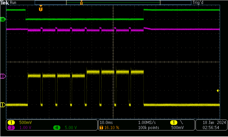
The capture above shows a single frame of mid range, 6ms per phase.
- yellow: IR emitter current (1V=1A)
- purple: IR emitter voltage (3.3V nominal)
- green: IR emitter disable signal (low=enable)
- as seen in this diagram, for 9-phase modes, there are 4 pulses of one amplitude (1.0A) and another 4 pulses of slightly higher amplitude (1.1A).
- M0178 is designed to support these current bursts by using a 3A DC/DC from the 5V input.
Technical Drawings
3D STEP File
M0178-1 PCB PMD IRS2975C Module
2D Diagram
Module Connector Pinout
Pin-out P1
Connector Specs
The 40-pin connector on M0178 is the new future format ModalAI will slowly be transitioning to that will replace the 24-pin and 36-pin connectors currently used across our image sensor line. This change will take place slowly, but it is a welcome improvement and capability enhancement.
The family from Molex is referred to as the Slimstack SSB RP series, and is a 0.35mm fine pitch B2B style, but includes a 3.0A power delivery contact system in addition to the noted pin counts. So, the 40-pin family we use provides 40 signal/GND pins and a 3.0A capable power feed system, which we define with 5V.
We defined the PLUG to be at the sensors, and the Receptacle to be on the Host (VOXL 2) side. This is more common in industry where the plug is free floating in space, and the receptacle is more “fixed” in place. We will use “Px” and “Jx” reference designators accordingly. The default mating height of this series as we use them are 0.8mm, but there are limited combinations that support 0.9mm.
| VOXL 2 Board Connector (via an adapter such as M0172/M0173) | M0178-1 P1 Connector |
|---|---|
| Molex, Receptacle MPN 5052704012, 0.8mm mate height | Molex, Plug MPN 5052744012 |
| Molex, Alternate Receptacle MPN 5054134010, 0.9mm mate height | Molex, Plug MPN 5052744012 |
Pin-out at P1
| Pin # | Signal Name | Pin # | Signal Name |
|---|---|---|---|
| 41 | GND (NAIL_1a) | 42 | GND (NAIL_1b) |
| 1 | N.C. | 2 | N.C. |
| 3 | VREG_L7_1P8 (DOVDD) | 4 | VREG_3P3V_LOCAL |
| 5 | N.C. | 6 | N.C. |
| 7 | N.C. | 8 | GND |
| 9 | GND | 10 | N.C. |
| 11 | CSI_CLK_P | 12 | N.C. |
| 13 | CSI_CLK_N | 14 | N.C. |
| 15 | CSI_LANE0_P | 16 | N.C. |
| 17 | CSI_LANE0_N | 18 | GND |
| 19 | CSI_LANE1_P | 20 | RESET_N (Unused, pulled HIGH on M0178) |
| 21 | CSI_LANE1_N | 22 | N.C. |
| 23 | GND | 24 | CCI_I2C_SDA (1.8V DOVDD levels) |
| 25 | N.C. | 26 | CCI_I2C_SCL (1.8V DOVDD levels) |
| 27 | N.C. | 28 | N.C. |
| 29 | N.C. | 30 | N.C. |
| 31 | N.C. | 32 | GND |
| 33 | GND | 34 | MCLK (1.8V DOVDD levels) |
| 35 | N.C. | 36 | N.C. |
| 37 | VREG_3P3V_LOCAL | 38 | N.C. |
| 39 | N.C. | 40 | N.C. |
| 43 | VDC_5V_LOCAL (NAIL_2a) | 44 | VDC_5V_LOCAL (NAIL_2b) |
Pay close attention to the pinout details in this image so that any custom hardware design maps pin 1 to pin 1, including the power nail features:
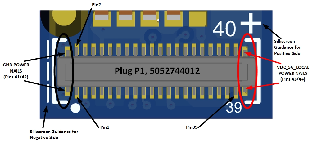 Note the Power Nail pins are numbered 41, 42, 43, and 44 and are on both sides of the connector, with 41/42 being nearer to the Pin 1 side.
VOXL 2 Integration
| Item | Value |
|---|---|
| Sensor type in voxl-camera-server | pmd-tof-liow2 |
| Standard camera configurations | VOXL 2 (platform config 1, M0173 adapter): C26, C27, C29, C30. Selected by sensor type; the configuration files name the M0173 adapter, not this module. Configuration 24 (platform config 0) is the 36-pin J6 lower path used by the M0169, not the 40-pin path this module requires. See the VOXL 2 camera configurations page. Run voxl-configure-cameras help on the device for the list shipped with your SDK release. |
| Connects to VOXL 2 via | M0170-1 40-pin extension flex or M0177 flex to the 40-pin ToF connector on M0173 (J3, the adapter listed in the requirements table); M0172 also exposes the 40-pin connector (J1L) |
| Connects to VOXL 2 Mini via | Listed as future in the requirements table on this page. The M0172 page shows VOXL 2 Mini to M0172 to M0177 to M0178; no platform config 2 standard configuration selects pmd-tof-liow2. |
| Calibration | Not calibrated with the chessboard tool. |
VOXL SDK
This guide assumes that you are able to run commands on VOXL2; if you cannot, please see VOXL Developer Bootcamp. All commands specified below should be run on VOXL2.
Supported Sensor Module
- M0178-1 IRS2975C Module on VOXL 2 through the M0173 adapter (platform config 1 camera configurations; the M0173 requires SDK 1.3 or greater)
IRS2975C Camera Server Configuration
Connect the module to the 40-pin ToF connector on the M0173 (J3). The platform config 1 standard configurations that include a pmd-tof-liow2 slot are C26, C27, C29 and C30 (see VOXL 2 camera configurations). Select one with its ID number:
voxl-configure-cameras 26
For a camera set that is not covered by a standard configuration, start from the nearest one and edit /etc/modalai/voxl-camera-server.conf, keeping "type": "pmd-tof-liow2" for the ToF entry.
After configuring, reboot VOXL 2 to reload the camera server configuration. To verify functionality, see the VOXL Portal section below.
VOXL Portal
In order to verify the functionality of your ToF configuration, you can attempt to view the IR and depth map images in VOXL portal. In order to view VOXL portal, your VOXL should be connected to the internet (see VOXL2 WiFi Setup).
After your VOXL is connected to the internet, run systemctl status voxl-portal. Then, find the IP address of your VOXL using hostname -I and visit this address in the web browser of a computer connected to the same local network as your VOXL (or your VOXL’s access point, in AP mode). Then, navigate to “Cameras > TOF Conf / Depth / IR” in the top navigation bar, and verify that the displayed video stream matches what the camera is pointed at.
Image Samples for Sensor
Indoor
Outdoor
Hardware Design Guidance
If designing your own custom hardware, here are other things to keep in mind to adapt to M0178:
All MIPI CSI Lines are to be impedance controlled at 100-ohms differential.
- Match the _P/_N skew to within 0.2mm, and all diff pairs within the group to be +/- 0.5mm
- Keep the overall length of the MIPI CSI lines to be less than 120mm or a re-driver may be required
- VOXL 2 already has 2.2K pullups on CCI I2C lines to DOVDD
- The 5V must be heavily bypassed with bulk capacitors, and provide several vias throughout the power route flow to support sustained 2A draws
- Starling will incorporate a thermal spreader on the TOF module, and we recommend your design plans for some type of thermal allocation as well to deal with the ~3W consumption of the PMD module
- Be sure to complete a 3D fit check using our 3D models linked above. We have several caps very close to the connector, and with a 0.8mm mate height, care must be taken to avoid interferences from components.
- RESET_N noted above in the pinout table is held HIGH on M0178. We do not expect to ever need to control it with a GPIO/RESET_N signal, but if making your own hardware, it may be worthwhile to provide this feature should we decide to use it in the future.
- We have plans to connect this TOF adapter to both LOWER and UPPER CSI ports throughout VOXL 2, so please check the camera configs to make sure we have your specific CSI port enabled for this TOF before committing to design tapeout.